Article

Removal Characteristics of Sapphire Lapping using Composite Plates with Consciously Patterned Resinoid-Bonded Semifixed Diamond Grits

1
Institute of Manufacturing Engineering, Huaqiao University, Xiamen 361021, China
2
National & Local Joint Engineering Research Center for Intelligent Manufacturing Technology of Brittle Materials Products, Xiamen 361021, China
*
Author to whom correspondence should be addressed.
Crystals 2020, 10(4), 293; https://doi.org/10.3390/cryst10040293
Submission received: 28 February 2020 / Revised: 5 April 2020 / Accepted: 8 April 2020 / Published: 11 April 2020
(This article belongs to the Special Issue Sustainable Approach in Synthetic Ceramic Materials)

Abstract

:
Sapphire lapping is of key importance for the successful planarization of wafers that are widely present in electronic devices. However, the high hardness of sapphire makes it extremely challenging to improve its material removal rate during the lapping process without compromising surface quality and dimensional accuracy. In this work, a novel composite lapping plate consisting of a rigid resin frame and flexible sol–gel balls was fabricated with consciously designed patterns. Through lapping experiment, it was revealed that the diamond grits imbedded in the sol–gel balls can effectively lap the sapphire at a promising material removal rate (MRR), without the formation of undesirable scratches and loss of surface integrity. Moreover, by designing the arrangement patterns of sol–gel balls, the total thickness variation (TTV) can also be ensured for lapped sapphire substrates. The implications of experimental results were also discussed based on the trajectory analysis and contact mechanics of lapping grits in order to demonstrate the potential of the newly developed composite abrasive tools for sapphire-lapping applications.

1. Introduction

Monocrystalline α-alumina, known as sapphire, is one of the most important engineering ceramics. Because of its superior mechanical and optical properties [1,2,3,4], sapphire is widely present in applications from electronic devices to military equipment and aircrafts [5,6,7]. In particular, the recent development of the melt–growth method has enabled the mass production of sapphire ingots that are subsequently planarized as the substrate of light-emitting diodes (LEDs). In general, the planarization of as-grown sapphire ingots involves a successive process of slicing, grinding, and chemical mechanical polishing (CMP). Owing to the small tolerance of lattice distortion, the planarized substrates must have ultra-high surface quality and dimensional precision, and more importantly, be free from subsurface damage. Given the high hardness of sapphire, lapping is commonly used to machine the sliced sapphire substrates with the required surface quality and dimensional accuracy, making them ready for subsequent polishing. An optimal balance between surface quality and a good material removal rate is the key for the success in the lapping of sapphire. Although considerable research effort has been dedicated to improving the material removal rate (MRR) during sapphire lapping, little progress has been achieved as the improvement of MRR is often linked with a loss of surface/subsurface integrity and dimensional accuracy. This dilemma may be attributed to the fact that sapphire lapping is carried out using plates with either free or fixed diamond abrasives. The former are associated with an uncontrollable trajectory of free diamond abrasives, which not only reduces the MRR but also makes it difficult to guarantee the dimensional accuracy of the lapped sapphire substrate; the latter often suffer from the formation of surface scratching or subsurface damage due to the nonuniform height of fixed diamond abrasives.
Alternatively, sapphire lapping using the composite lapping plates containing sol–gel diamond abrasive balls has been proposed as a promising means to simultaneously achieve an MRR higher than that achieved using free diamond abrasive tools and ensure the surface/subsurface integrity and dimensional accuracy of lapped sapphire [8,9,10,11,12]. On the one hand, the sol–gel ball is relatively soft and can somehow bundle the humped diamond girts on lapping plates, which effectively improves the uniformity of grit protrusion, reduces scratch formation, and ensures surface integrity of lapped sapphire. However, it must be noted that the flexibility of sol–gel balls can also result in an the overall deformation of lapping plates, impairing the dimensional accuracy of lapped sapphire. Hence, it is desirable to fabricate a composite lapping plate that consists of a rigid resin frame and flexible sol–gel diamond grits balls. Our previous research indicated that the rigid resin frame can reduce the overall deformation of lapping plates, and hence improve the dimensional accuracy of lapped SiC [13]. In particular, the use of resin can effectively avoid the formation of scratches on the lapped surface of single-crystal SiC. However, a systematic understanding on the removal characteristics of monocrystalline ceramics is yet to obtained by taking the role of lapping pressures and trajectory of diamond grits into account.
In this work, novel composite lapping plates that consist of a rigid resin frame and flexible sol–gel balls were fabricated based on the trajectory analysis of variable patterns of diamond abrasive blocks. Then, lapping experiments were carried out on commercial sapphire substrates to reveal the influence of variable lapping parameters on removal characteristics such as MRR, surface roughness, and dimensional accuracy. Our experimental results demonstrated the feasibility for improving the lapping efficiency and quality by consciously designing the pattern of abrasive blocks on the composite lapping plates.

2. Trajectory Analysis and Pattern Design

The trajectory of lapping/grinding grits plays a determinant role in the material removal characteristics, surface quality, and dimensional accuracy of lapped workpieces. It has been revealed that the more uniform the trajectory of grinding grits, the higher the MRR and surface integrity of ground and lapped surfaces of sapphire [14,15]. Hence, trajectory analysis not only promises an understanding of the difference in the performance of abrasive tools during sapphire lapping, but also provides a useful reference for the design of lapping plates, especially the arrangement of abrasive blocks. To represent the abrasive trajectory on a workpiece, a mathematic model was developed in accordance with the movement of abrasive grits on lapping plates.

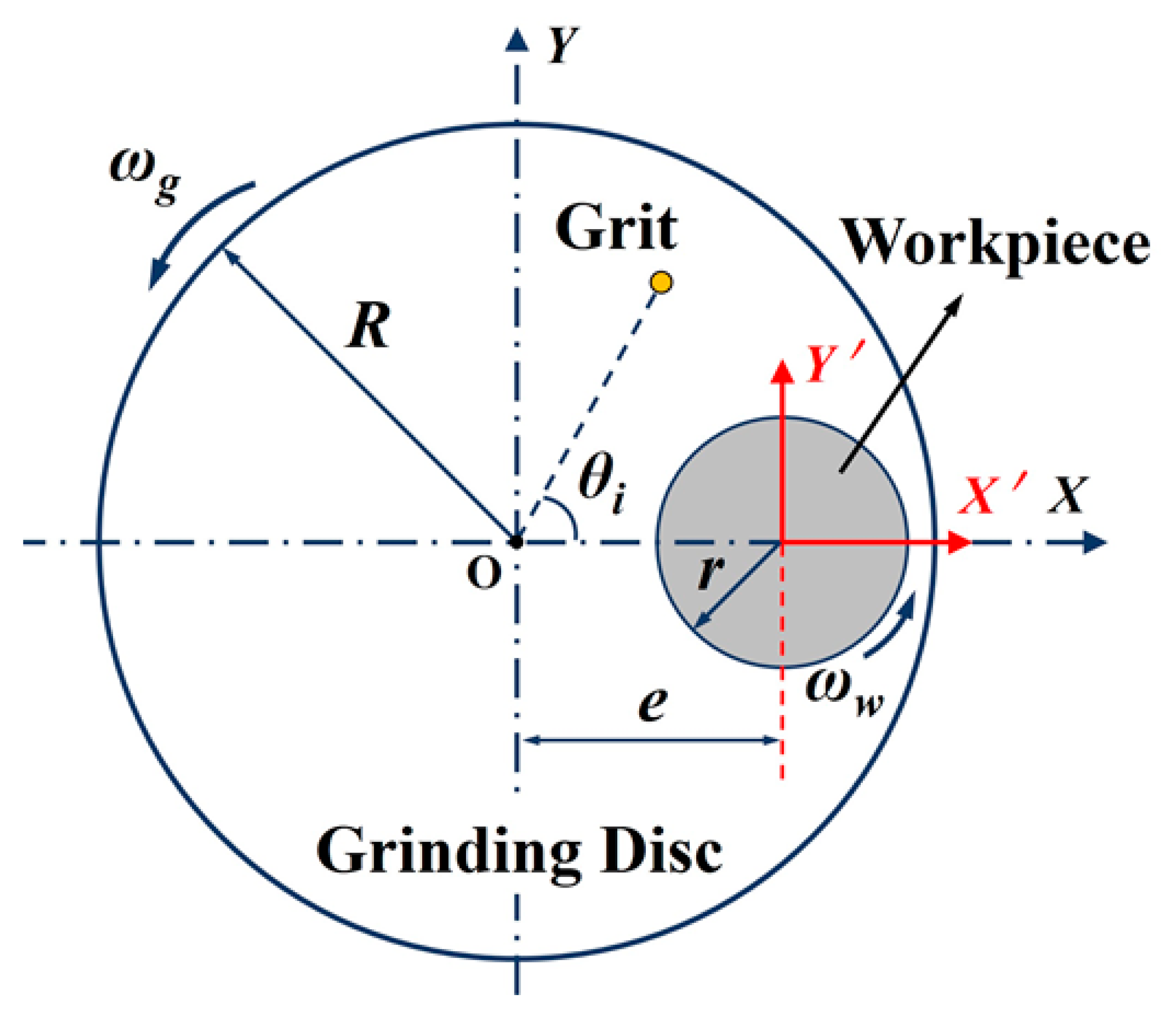
2.1. Trajectory Modelling

Figure 1 illustrates the trajectory of a grit for typical single-side lapping or grinding. Clearly, the trajectory of a certain lapping grit is dependent on not only the geometrical configuration and relative position of lapping plate and work piece, but also their kinematics, as determined by the lapping parameters.
According to Fang et al. [16], the trajectory of a lapping grit illustrated in Figure 1 can be expressed as:
{ X i = r i cos ( θ i + ω g t     ω w t ) + ecos ( ω w t ) Y i = r i sin ( θ i + ω g t     ω w t )     esin ( ω w t ) }
where ωg and ωw are the rotating speed of the plate and the workpiece, respectively. e is the eccentricity referring to the distance from the plate center to the workpiece. r is the distance from the abrasive point to the plate center, and θ is the initial angle for the abrasive point. Subscript i denotes the abrasive number. Based on Equation (1), the trajectory of i-th abrasive on the workpiece can be readily calculated. Thus, the total trajectories on lapped workpiece can be obtained through the superposition of the trajectory of each abrasive involved. For convenience, the rotating ration n was introduced here, which can be written as
n = ω w l ω g
When analyzing the trajectory of a large number of abrasive particles, it is difficult to distinguish the distribution characteristics merely through observing the trajectory map. Therefore, an appropriate evaluation method must be adopted to test trajectory uniformity. Considering the changes of abrasive distribution and processing parameters (such as speed ratio), not only the distribution of abrasive trajectory but also the counted number of abrasive trajectory points will change. Su [17] proposed the non-uniformity coefficient WIWNU to represent the uniformity of the abrasive trajectory, which can be calculated as:
WIWNU   ( % ) = K s N std N avg   ×   100 %
where Nstd is the statistical standard deviation of the counted number of tracked trajectory points, Navg is the average value of the counted number of tracked trajectory points, and ks is the correction coefficient and equals 1. In doing so, the trajectory of a large number of abrasives on single-side lapping plates with variable patterns can be estimated, taking both the geometric configurations and lapping parameters into account.

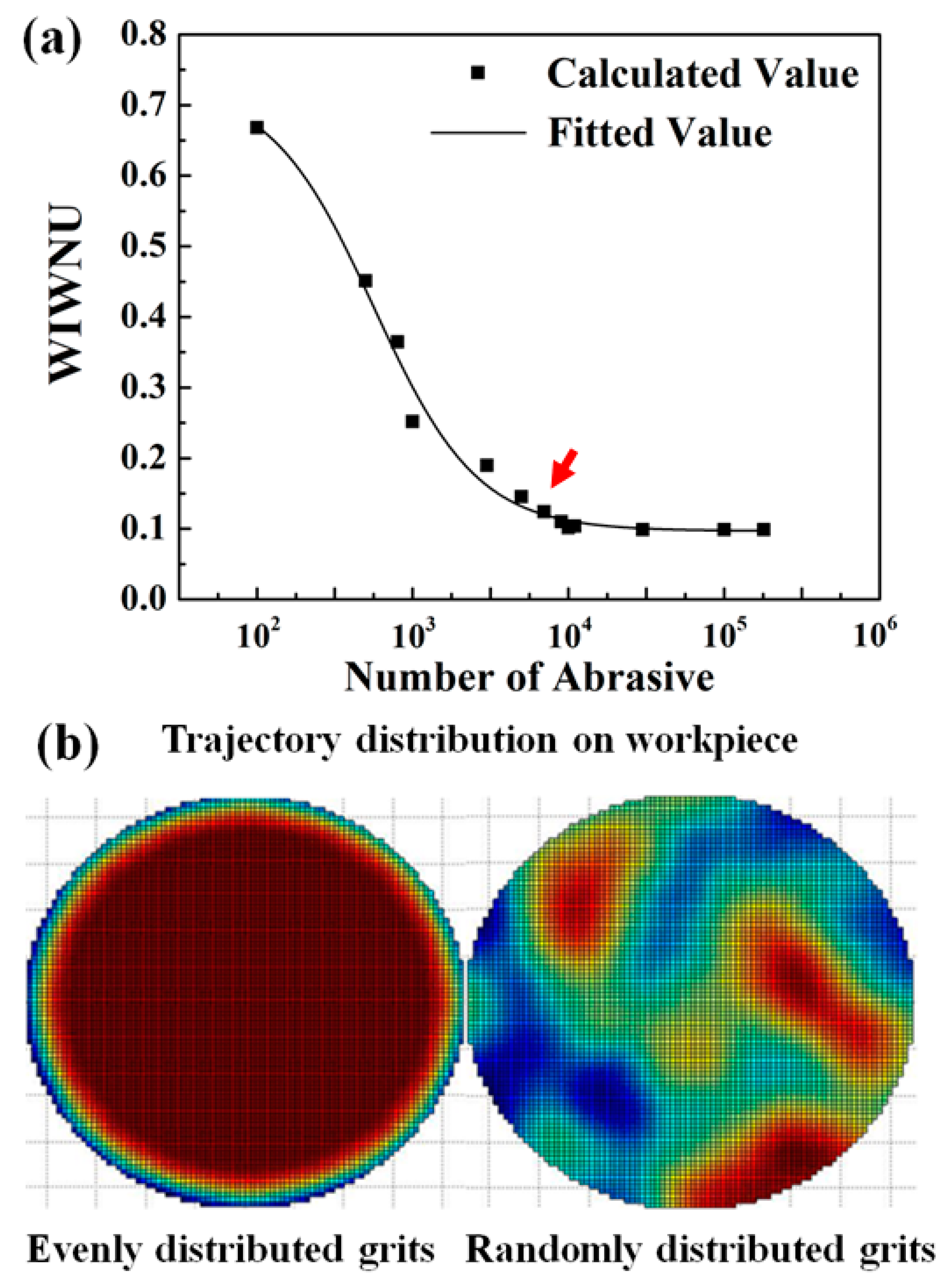
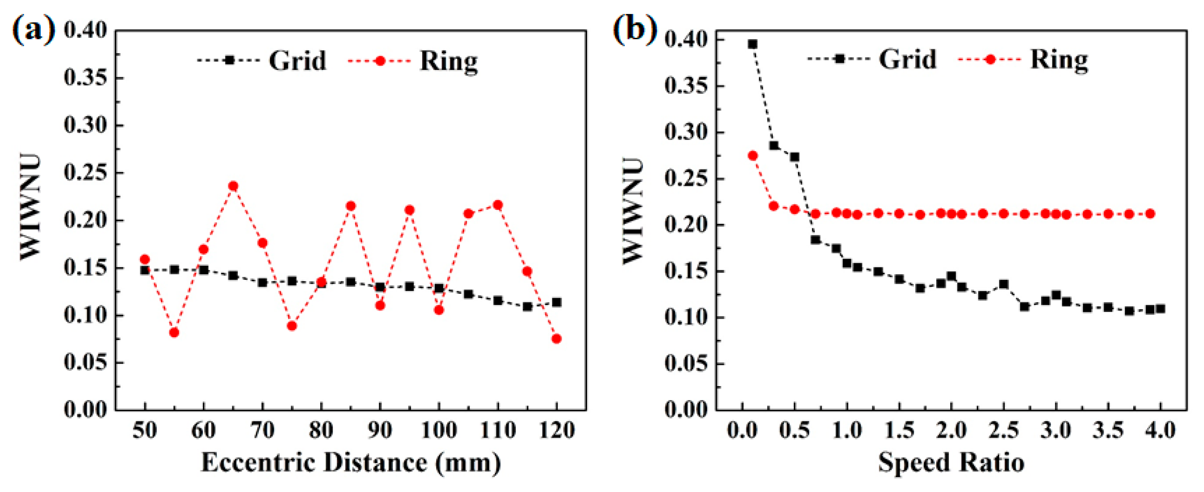
2.2. Trajectory Uniformity Estimation

During lapping process, the number or superficial density of grits on a lapping plate is one of the key parameters for ensuring the uniformity of grit trajectory on the workpiece. Figure 2a shows the calculated variation of trajectory non-uniformity coefficient against the number of grits involved during the single-side lapping process. It can be seen that the grit number strongly influences the trajectory uniformity and as marked by the red arrow in Figure 2a, the change of trajectory uniformity coefficient became relatively stable after the grit number was increased to 8000, corresponding to a superficial density of 0.12 mm−2. Hence, our calculation results indicated that, in order to ensure the trajectory uniformity, the superficial density of lapping grits should be more than 0.12 mm−2. Moreover, as shown in Figure 2b, taking the superficial density of grits as 0.14 mm−2 and transmission ratio as 1, the trajectory distribution on workpiece was more uniform when the grits were evenly distributed on lapping plates. This suggested that an even and consciously designed distribution of abrasive blocks on lapping plates could also be beneficial for improving the trajectory uniformity on a lapped workpiece, which is in agreement with the comparative study on the lapping experiment using free and fixed abrasive tools.
In addition, based on the aforementioned framework for trajectory analysis, it is also feasible to compare the trajectory uniformity on the workpieces lapped by plates of variable arrangements of abrasive blocks. In this work, two of the most commonly used patterns, namely the concentric ring and grid arrangement as shown in Figure 3, were designed to reveal their effects on trajectory uniformity during single-side lapping. According to the calculation results given in Figure 2a, the superficial density of grits on lapping plates was set as 0.14 mm−2 in order to minimize its effect on the trajectory uniformity on workpiece. Then, the workpiece trajectory uniformity was estimated by setting the diameters of the lapping plate, workpiece, and abrasive blocks at 300 mm, 50 mm, and 10 mm, respectively. When the intermitted distance between abrasive blocks (Figure 3) was 3 mm, the variation of trajectory uniformity against the change in eccentric distance between the workpiece and the lapping plate was calculated (Figure 4a). It can be seen that when the abrasive blocks were arranged in a concentric ring pattern, the trajectory non-uniformity coefficient of lapping grits on the workpiece periodically fluctuated with the increase of the concentric distance. On the other hand, when the abrasive blocks were arranged in a grid pattern, the trajectory non-uniformity coefficient of the lapped workpiece was almost monotonously decreased with the increase of concentric distance, indicating a continuous improvement of trajectory uniformity on the lapped workpiece. Based on the calculated trajectory and geometric configuration of lapping plate and workpiece, the concentric distance can be taken as 90 mm. Therefore, the effect of transmission ratio on the trajectory uniformity can be further calculated as shown in Figure 4b. It can be found that when the transmission ratio is less than 1, the trajectory uniformity was increased with the increase in transmission ratio. When the transmission was above 1, the trajectory non-uniformity coefficient of workpiece lapped by plate of abrasive blocks arranged in a concentric ring pattern was nearly constant. However, the trajectory uniformity coefficient for workpiece lapped with the abrasive blocks arranged in grid pattern was increased with the increase in transmission ratio. In reality, the transmission ratio feasible for a lapping process is in the range of 0.7–2; it is therefore recommended that the transmission ratio be in the range from 1.2 to 1.3, where the trajectory uniformity started to become stable.
Figure 5 shows the calculated the non-uniformity coefficient WIWNU for composite lapping plates with concentric ring and grid patterns. It should be mentioned that a smaller value of WIWNU indicates a better trajectory distribution on the workpiece surface, which is more helpful to improve the workpiece surface quality. Clearly, the concentric ring arrangement of sol–gel balls always gave a higher WIWNU value than that in a grid arrangement, which suggests that, in addition to the reduced overall deformation of lapping plates, a consciously designed pattern of abrasive blocks should also give a better dimensional accuracy through the improvement of trajectory uniformity.

3. Experimental validation

In order to experimentally validate the effect of trajectory on the surface integrity and dimensional accuracy of lapped sapphire, composite lapping plates with rigid resin frame and semi-flexible sol–gel abrasive balls were designed according to the calculation results given in Figure 5. Specifically, composite lapping plates with the abrasive blocks arranged in both a grid pattern with spacing distance of 1 mm and concentric ring pattern with spacing distance of 5 mm were prepared. Moreover, the lapping experiment was conducted to reveal the material removal characteristics of sapphire substrates lapped under variable pressure forces.

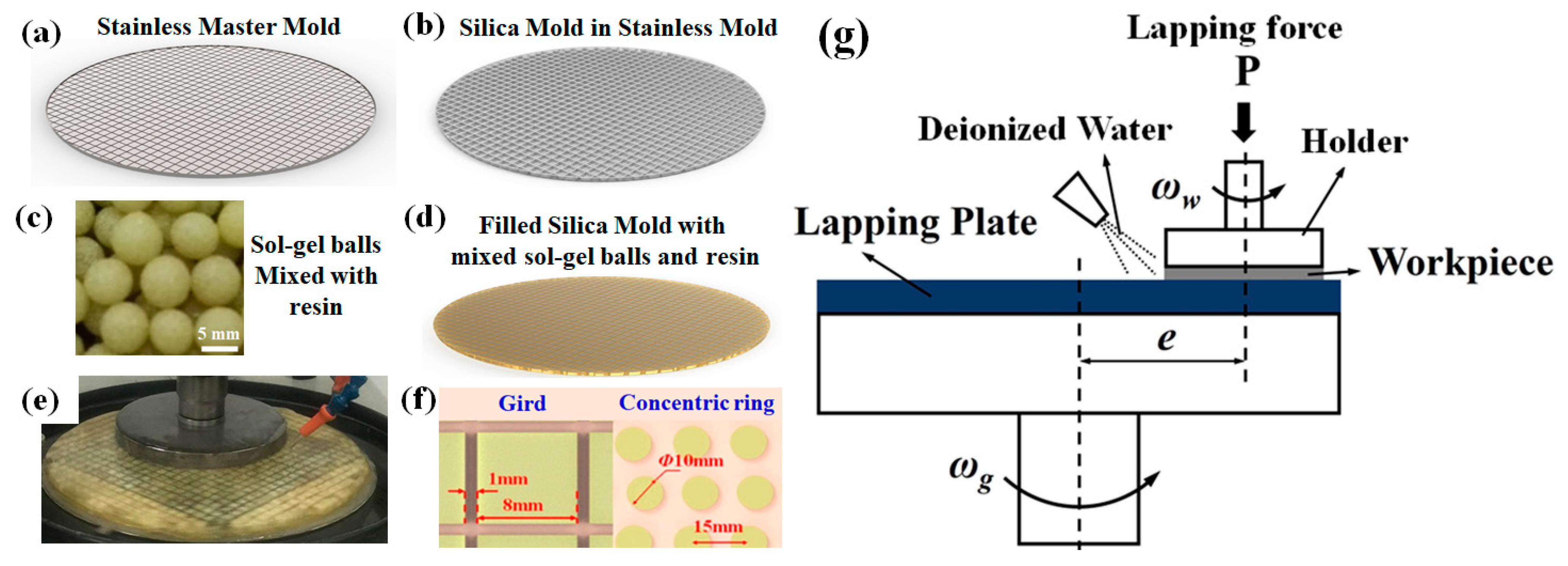
3.1. Materials and Method

As illustrated in Figure 6, composite lapping plates were developed by casting the mixture of sol–gel abrasive balls and epoxy resin in a silica mold with a pre-designed configuration. To fabricate lapping plates with designed patterns, a mold was firstly made by casting silica gel and hardener in a mass ratio of 100:2~3 in a stainless-steel prototype mold as shown in Figure 6a. After aging for 5 h, the silica gel mold was released as shown in Figure 6b. Then, the sol–gel balls (see Figure 6c) with a diameter of 3.5 mm and 15 mass% of diamond abrasives in grit sizes from 10 to 20 µm were mixed with epoxy resin and hardener in a mass ratio of 2:1, casted in the prepared silica gel mold as shown in Figure 6d, and dispersed by mechanical vibration for 10 min. After the sol–gel balls were evenly distributed in epoxy resin, the plates were manually scrapped and aged in a silica mold for 24 h. For detailed information of the preparation of sol–gel balls, please refer to [18,19]. Figure 6e shows a representative sample of prepared lapping plates. As shown in Figure 6f, both concentric ring and grid patterns of the abrasive blocks were designed according to the trajectory analysis results. The prepared lapping plates are shown in Figure 3. As shown in Figure 6g, the lapping experiment was carried out on a UNIPOL-1200S (KEJING AUTOINSTRMENT CO., LTD, Shenyang, China) automate polisher. The original C-plane sapphire substrates with a surface roughness 0.8–1.2 µm and a thickness of 670–695 µm were purchased from Sanan Co. Ltd. and used as workpieces. During the lapping experiment, the sapphire workpiece was glued on sample holder using wax. Lapping pressure was manipulated by changing the lapping forces from 4, 8, 12, and 16 kg. The sample holder and lapping plate were inversely rotating at speed of 50 and 60 rpm, respectively. The lapped sapphire was cleaned in an ultrasonic alcohol bath, dried by pressured air, and weighted on an electronic balance with an accuracy of ± 0.1 mg. The material removal rate was calculated based on the change of workpiece weight averaged from five measurements using Equation (1) [20]:
MRR = 10 7 × m ρ × S × t
where m is the change of mass, ρ is density of sapphire (3.98g/cm3), S is the surface area of sapphire workpiece (101.6 mm for 4-inch sapphire substrate), and t is the lapping time.
A 3D white light interferometer (NewView 7300, ZYGO, USA) was used to obtain the surface morphology of lapped sapphire substrates, and the roughness Sa was averaged from nine measurements evenly taken on lapped sapphire in an area of 70 μm × 50 μm. For each measurement, the Tropel Flatmaster system was used to measure the total thickness variation (TTV) of lapped samples.

3.2. Surface Roughness and Thickness Variation

Figure 7a shows the surface roughness of original and sapphire substrates lapped using composite plates with sol–gel balls arranged in a concentric ring pattern and grid pattern for 90 min. It can be seen that the surface roughness of sapphire substrates lapped using the newly developed composite plates with both types of patterns was slightly reduced. This evidenced the capability of semi-fixed bonded diamond grits to remove the sapphire and avoid the formation of scratches during lapping process. It should be noted that the composite lapping plates with a concentric ring pattern of sol–gel balls gave a lower surface roughness, Ra, than the counterpart with grid-patterned sol–gel balls, but this was associated with a larger standard deviation. Taking the change of total thickness variation (TTV) result given in Figure 7b into consideration, it is reasonable to propose that both the larger Ra standard deviation and the increased TTV value of sapphire substrates lapped using composite plates with sol–gel balls arranged in a concentric ring pattern are closely related to the different trajectory of lapping diamond grits.

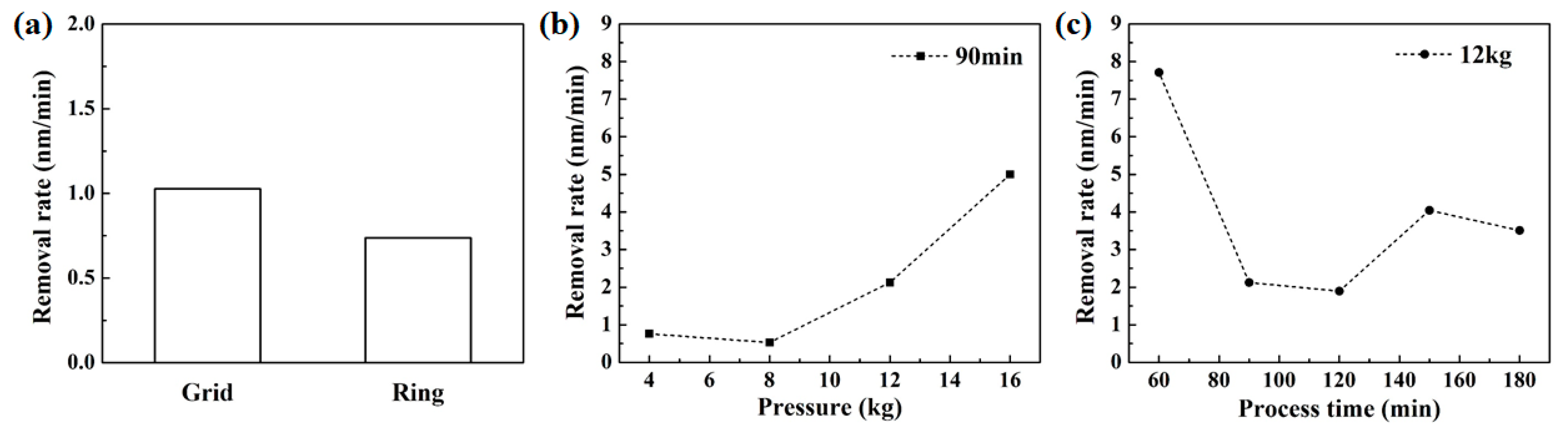
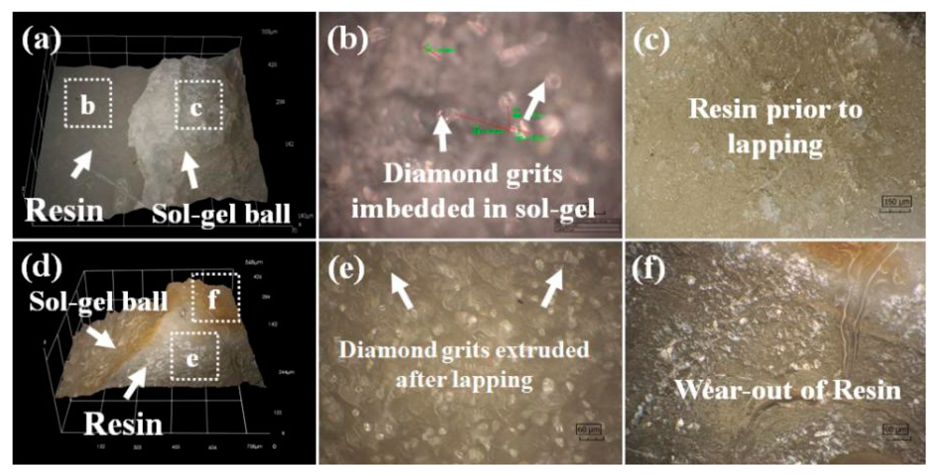
3.3. Material Removal Characteristics

Figure 8 shows the material removal rates of sapphire substrates lapped using the composite plates with sol–gel balls arranged in concentric circle and grid patterns. It can be seen in Figure 8a, under a lapping force of 4 kg, that the sapphire can be removed by the sol–gel balls containing diamond grits with a grain size of W20 at a removal rate of approximately 1 nm/min. Moreover, when the composite lapping plates were of a grid pattern, the corresponding MRR was slightly higher than that achieved by lapping plates with a concentric circle pattern of sol–gel balls. As shown in Figure 8b, when the lapping force was increased from 4 to 8, 12, and 16 kg, the MRR of sapphire lapped for 90 min was also accordingly increased. In particular, when the applied lapping force was 8 kg, the MRR of lapped sapphire was approximately 1 nm, almost same as that obtained under lapping force of 4 kg. This value is slightly smaller than that obtained using a similar so-gel lapping plate, mostly likely due to the existence of rigid resin frame that reduced the contact area between workpiece and lapping plate. However, when the lapping force was further increased to 12 and 16 kg, the maximum MRR of sapphire was dramatically increased to around 5 nm after lapping for 90 min, which is even higher than the value obtained in our previous study on sapphire lapping using diamond grits of a larger grain size. Recalling the fact that sapphire can only be removed by the lapping diamond grits in the sol–gel ball, the sudden change of MRR value suggested a threshold value of lapping force, beyond which the contact mechanics of sapphire and diamond grits buried in sol–gel was modified, resulting the increase in MRR. Last but not least, as shown in Figure 8c, the MRR of sapphire lapped using the composite plate with a grid pattern of sol–gel balls was also time-dependent: after lapping under the force of 12 kg for 60 min, the MRR quickly decreased from 7.7 to around 2.1 nm/min, and conversely increased to 4 nm/min after when the lapping time was increased to 160 min. The high MRR during the initial lapping stage is mostly likely due to the wear of sol–gel in composite lapping plates explored the diamond grits that were originally buried in sol–gel balls, and hence improve the contact between lapping diamond grits and sapphire substrate. However, as the lapping process continued, the explored diamond grits became detached, resulting in a low MRR. As the sol–gel was continuously worn out, the aforementioned process was repeated, and consequently the MRR had a time-dependent characteristic during the lapping process.
To validate the above-mentioned mechanism and reveal the role of lapping force in the material removal characteristics of sapphire, the topographies of composite lapping plates were obtained and are given in Figure 9. In Figure 9a, it can be clearly seen that, as on prepared composite lapping plates, the rigid resin frame overtopped the sol–gel ball due to the shrinkage that occurred during the aging process of sol–gel. Moreover, as shown in Figure 9b,c, the diamond grits were mainly imbedded in the sol–gel matrix, and the surrounding resin frame was intact. However, after lapping experiment, the resin frame was preferentially worn out as shown in Figure 9d, and the diamond grits were extruded in Figure 9e. Hence, the increase of MRR at a higher lapping force is closely related to the deformation and wear of resin frame and sol–gel balls in the composite lapping plate.
Based on above discussion, the effect of lapping on the MRR of lapped sapphire can be understood. As illustrated in Figure 10, initially, the sol–gel ball was on a low-lying level on composite lapping plates free from lapping force. However, when a relatively small lapping force was applied, it was mainly supported by the resin frame because of the higher elastic modulus and hardness as compared to sol–gel balls. Consequently, the low-lying sol–gel balls were not fully in contact with sapphire, and the MRR was not changed when the applied lapping force was insufficient (i.e., 6 kg in this work). However, the higher lapping force was applied, a larger deformation of resin frame was endured. As shown Figure 10b, when the lapping force was above a threshold value (i.e., 12 kg as revealed in Figure 2), the increased deformation of resin frame resulted in an extrusion effect on sol–gel balls that considerably facilitated the contact between the sapphire substrate and the diamond grits contained in sol–gel balls. As a result, the MRR was dramatically increased beyond the threshold value of the lapping force component of the composite plate. As the lapping force was further increased, the extrusion of sol–gel balls and consequently the number of diamond grits in contact with sapphire substrate were accordingly increased, leading to a further increment of the MRR as shown in Figure 8b.

4. Conclusions

In this work, the effects of geometric configuration of lapping plates on the trajectory uniformity of lapped workpiece were investigated by taking the lapping parameters into account. Subsequently, a novel composite lapping plate that consisted of a rigid resin frame and semi-fixed sol–gel diamond abrasive balls was fabricated with the consciously designed patterns. A single-side lapping experiment was carried out using the novel composite lapping plates to reveal the influence of trajectory uniformity that was associated with variable patterns on the material removal characteristics, surface integrity, and dimensional accuracy of lapped sapphire substrates. It was evidenced that commercial sapphire substrates can be effectively lapped at a promising removal rate. More importantly, the surface quality and dimensional accuracy of lapped sapphire substrates were also essentially improved. The experimental results and discussion presented in this work will lay a foundation for the future development of novel abrasive lapping tools that are badly needed by the electronics industry.

Author Contributions

W.W. and Z.H. conceived and designed the experiments; W.W. and C.F. performed the experiments and analyzed the data; J.L. provided materials, and Y.Y. and X.X. made critical revisions to the article. All authors have read and agreed to the published version of the manuscript.

Funding

This research was funded by National Natural Science Foundation of China of grant number 51575197, 51675193, and 51675192.

Acknowledgments

This research is financially supported by National Natural Science Foundation of China (51575197, 51675193, and 51675192).

Conflicts of Interest

The authors declare no conflict of interest.

References

  1. Gagliardi, J.J.; Kim, D.; Sokol, J.J.; Zazzera, L.A.; Romero, V.D.; Atkinson, M.R.; Nabulsi, F.; Zhang, H. A case for 2-body material removal in prime LED sapphire substrate lapping and polishing. J. Manuf. Process. 2013, 15, 348–354. [Google Scholar] [CrossRef]
  2. Kim, D.; Kim, H.; Lee, S.; Lee, T.; Jeong, H. Characterization of diamond wire-cutting performance for lifetime estimation and process optimization. J. Mech. Sci. Technol. 2016, 30, 847–852. [Google Scholar] [CrossRef]
  3. Kim, D.; Kim, H.; Lee, S.; Jeong, H. Effect of initial deflection of diamond wire on thickness variation of sapphire wafer in multi-wire saw. Int. J. Precis. Eng. Manuf.-Green Technol. 2015, 2, 117–121. [Google Scholar] [CrossRef]
  4. Aida, H.; Doi, T.; Takeda, H.; Katakura, H.; Kim, S.-W.; Koyama, K.; Yamazaki, T.; Uneda, M. Ultraprecision CMP for sapphire, GaN, and SiC for advanced optoelectronics materials. Curr. Appl. Phys. 2012, 12, S41–S46. [Google Scholar] [CrossRef]
  5. Li, J.; Nutt, S.R.; Kirby, K.W. Surface Modification of Sapphire by Magnesium-Ion Implantation. J. Am. Ceram. Soc. 1999, 82, 3260–3262. [Google Scholar] [CrossRef]
  6. Lee, T.; Jeong, H.; Kim, H.; Lee, S.; Kim, D. Effect of platen shape on evolution of total thickness variation in single-sided lapping of sapphire wafer. Int. J. Precis. Eng. Manuf.-Green Technol. 2016, 3, 225–229. [Google Scholar] [CrossRef]
  7. Smith, M.B.; Schmid, F.; Khattak, C.P.; Schmid, K.A.; Golini, D.; Lambropoulos, J.C.; Atwood, M.A.; Zhou, Y.; Funkenbusch, P.D. Sapphire fabrication for precision optics. In Advanced Materials for Optical and Precision Structures; International Society for Optics and Photonics: Denver, CO, USA, 1996; pp. 99–112. [Google Scholar] [CrossRef]
  8. Yuan, J.; Wang, Z.; Hong, T.; Deng, Q.; Wen, D.; Lv, B. A semi-fixed abrasive machining technique. J. Micromech. Microeng. 2009, 19, 054006. [Google Scholar] [CrossRef]
  9. Nakamura, H.; Yan, J.W.; Syoji, K.; Wakamatsu, Y. Development of a polishing disc containing granulated fine abrasives. In Key Engineering Materials; Trans Tech Publ.: Zürich, Switzerland, 2003; pp. 257–262. [Google Scholar] [CrossRef]
  10. Lv, B.H.; Yuan, J.L.; Wang, Z.W. Simulation of compacting process for semi-fixed abrasive wheel. In Key Engineering Materials; Trans Tech Publ.: Zürich, Switzerland, 2009; pp. 87–92. [Google Scholar] [CrossRef]
  11. Luo, Q.; Lu, J.; Xu, X. A comparative study on the material removal mechanisms of 6H-SiC polished by semi-fixed and fixed diamond abrasive tools. Wear 2016, 350, 99–106. [Google Scholar] [CrossRef]
  12. Luo, Q.; Lu, J.; Xu, X. Study on the processing characteristics of SiC and sapphire substrates polished by semi-fixed and fixed abrasive tools. Tribol. Int. 2016, 104, 191–203. [Google Scholar] [CrossRef]
  13. Yiqing, Y.; Zhongwei, H.; Wenshan, W.; Huan, Z.; Jing, L.; Xipeng, X. The double-side lapping of SiC wafers with semifixed abrasives and resin–combined plates. Int. J. Adv. Manuf. Technol. 2019, 1–10. [Google Scholar] [CrossRef]
  14. Yuan, J.; Yao, W.; Zhao, P.; Lyu, B.; Chen, Z.; Zhong, M. Kinematics and trajectory of both-sides cylindrical lapping process in planetary motion type. Int. J. Mach. Tools Manuf. 2015, 92, 60–71. [Google Scholar] [CrossRef]
  15. Wang, L.; Hu, Z.; Fang, C.; Yu, Y.; Xu, X. Study on the double-sided grinding of sapphire substrates with the trajectory method. Precis. Eng. 2018, 51, 308–318. [Google Scholar] [CrossRef]
  16. Fang, C.; Zhao, Z.; Lu, L.; Lin, Y. Influence of fixed abrasive configuration on the polishing process of silicon wafers. Int. J. Adv. Manuf. Technol. 2017, 88, 575–584. [Google Scholar] [CrossRef]
  17. Su, J.X.; Guo, D.M.; Kang, R.K.; Jin, Z.J.; Li, X.; Tian, Y. Modeling and analyzing on nonuniformity of material removal in chemical mechanical polishing of silicon wafer. In Materials Science Forum; Trans Tech Publications: Zürich, Switzerland, 2004; pp. 26–31. [Google Scholar] [CrossRef]
  18. Lu, J.; Li, Y.; Xu, X. The effects of abrasive yielding on the polishing of SiC wafers using a semi-fixed flexible pad. Proc. Inst. Mech. Eng. Part B J. Eng. Manuf. 2015, 229 (Suppl. 1), 170–177. [Google Scholar] [CrossRef]
  19. Xu, Y.; Lu, J.; Xu, X. Study on planarization machining of sapphire wafer with soft-hard mixed abrasive through mechanical chemical polishing. Appl. Surf. Sci. 2016, 389, 713–720. [Google Scholar] [CrossRef]
  20. Mu, D.; Feng, K.; Lin, Q.; Huang, H. Low-temperature wetting of sapphire using Sn–Ti active solder alloys. Ceram. Int. 2019, 45, 22175–22182. [Google Scholar] [CrossRef]
Figure 1. Schematic illustration of the trajectory of a grit during a typical single-side lapping process.
Crystals 10 00293 g001
Figure 2. (a) Plot of the non-uniformity coefficient of trajectory against the number of lapping grits; (b) trajectory distribution on a workpiece lapped by plates with evenly (left) and randomly (right) distributed grits.
Crystals 10 00293 g002
Figure 3. Geometric configuration of lapping with abrasive blocks in (a) concentric ring and (b) grid patterns.
Crystals 10 00293 g003
Figure 4. Plot of the non-uniformity coefficient of trajectory against (a) eccentric distance and (b) transmission ratio.
Crystals 10 00293 g004
Figure 5. Calculated non-uniformity of trajectory with concentric ring and grid arrangements of the sol–gel balls.
Crystals 10 00293 g005
Figure 6. (a) Stainless-steel mater mold; (b) casted silica gel mold; (c) sol–gel balls used in this work; (d) casted mixture of sol–gel balls and resin in silica mold; (e) prepared composite lapping plates; (e) pattern of abrasive blocks on lapping plates; (g) experiment set-up.
Crystals 10 00293 g006
Figure 7. (a) Surface roughness and (b) total thickness variation (TTV) of original and lapped sapphire substrates by composite plates with sol–gel balls arranged in concentric ring and grid patterns.
Crystals 10 00293 g007
Figure 8. Material removal rates (MRR) of sapphire lapped by plates (a) with concentric circles and grid patterns, (b) with grid patterns under variable lapping force, and (c) time histories of MRR of sapphire lapped with grid patterns under lapping force of 12 kg.
Crystals 10 00293 g008
Figure 9. Optical topography of the resin and sol–gel boundary (a) as-prepared and (d) after lapping for 90 min under a pressing force of 12 kg. (b,c,e,f) were sol–gel balls and resin matrix manifested from location marked by white box in (a) and (b), respectively.
Crystals 10 00293 g009
Figure 10. Illustration of the deformation of composite lapping plates with sol–gel balls embedded in resin frame: (a) as-prepared, (b) under a relatively small lapping force, (c) with balanced deformation under a threshold lapping force, and (d) with extrusion of sol–gel balls under excessive lapping force.
Crystals 10 00293 g010

