Communication

Modelling Propagating Bloch Waves in Magnetoelectroelastic Phononic Structures with Kagomé Lattice Using the Improved Plane Wave Expansion

by
Edson Jansen Pedrosa de Miranda, Jr.
1,2,*,
Samuel Filgueiras Rodrigues
2,
Clodualdo Aranas, Jr.
3,
Hélio Vitor Cantanhêde da Silva
4,
Eden Santos Silva
2,
Gedeon Silva Reis
2,
Antônio Ernandes Macedo Paiva
2 and
José Maria Campos Dos Santos
4
1
Federal Institute of Maranhão, IFMA-EIB-DE, Rua Afonso Pena, 174, São Luís CEP 65010-030, Brazil
2
Federal Institute of Maranhão, IFMA-PPGEM, Avenida Getúlio Vargas, 4, São Luís CEP 65030-005, Brazil
3
Department of Mechanical Engineering, University of New Brunswick, Fredericton, NB E3B 5A3, Canada
4
Faculty of Mechanical Engineering, University of Campinas, UNICAMP-FEM-DMC, Rua Mendeleyev, 200, Campinas CEP 13083-860, Brazil
*
Author to whom correspondence should be addressed.
Crystals 2020, 10(7), 586; https://doi.org/10.3390/cryst10070586
Submission received: 10 June 2020 / Revised: 26 June 2020 / Accepted: 30 June 2020 / Published: 7 July 2020
(This article belongs to the Special Issue Metamaterials)

Abstract

:
We studied the dispersion diagram of a 2D magnetoelectroelastic phononic crystal (MPnC) with Kagomé lattice. The MPnC is composed of BaTiO3–CoFe2O4 circular scatterers embedded in a polymeric matrix. The improved plane wave expansion (IPWE) approach was used to calculate the dispersion diagram (only propagating modes) of the MPnC considering the classical elasticity theory, solid with transverse isotropy and wave propagation in the xy plane. Complete Bragg-type forbidden bands were observed for XY and Z modes. The piezoelectric and the piezomagnetic effects significantly influenced the forbidden band widths and localizations. This investigation can be valuable for elastic wave manipulation using smart phononic crystals with piezoelectric and piezomagnetic effects.

1. Introduction

In the early nineties, phononic crystals (PnCs) were theoretically proposed [1,2]. The new characteristics of the PnCs emerged mainly from the possibility of opening up Bragg-type forbidden bands, also known as band gaps. The PnCs have many applications, for instance, wave manipulation [3], vibration isolation [4], acoustic filters [5], and waveguides [6]. Furthermore, smart periodic structures have been investigated, for instance, piezoelectric [7,8] and piezomagnetic [9] PnCs. Nevertheless, there are few studies regarding magnetoelectroelastic phononic crystals (MPnCs) [10,11,12,13,14,15]. Moreover, only Wang et al. [11] investigated the forbidden bands of MPnCs with a Kagomé lattice by means of the plane wave expansion (PWE). However, they [11] did not consider the correct expressions of the structure function and reciprocal lattice vector, obtaining incorrect dispersion diagrams for the Kagomé lattice. Thus, in order to improve the results reported by Wang et al. [11], we used the improved plane wave expansion (IPWE) approach, which presents high Fourier series convergence. We also corrected the expressions of the structure function and the reciprocal lattice vector for Kagomé lattice. This enhancement was important to obtain the correct dispersion diagrams of the MPnC with Kagomé lattice and to show the importance of considering IPWE for complex periodic systems. Furthermore, the Kagomé lattice was chosen in this study since it presents important characteristics, for instance, periodic collapse modes [16], isostatic modes [17], floppy modes [18], topologically protected edge waves [19], and both topologically protected bands as well as non-dispersing or flat bands [20]. In this context, the main objective of this communication was to study the dispersion diagram of a 2D MPnC with a Kagomé lattice composed of BaTiO3–CoFe2O4 circular scatterers in a polymeric matrix using the IPWE. The IPWE is more efficient than the traditional PWE when considering MPnCs, since the matrices associated with the eigenvalue problem are ill-conditioned [15]. We regarded in plane vibration (XY modes) and out of plane vibration (Z modes), i.e., wave propagation in the xy plane, in an inhomogeneous solid with transverse isotropy. The influence of piezoelectric and piezomagnetic effects on the MPnC dispersion diagram was investigated. Complete Bragg-type forbidden bands for in plane and out of plane vibrations are reported.

2. Magnetoelectroelastic Phononic Crystal Modelling

The IPWE is an approach that can be used to compute the dispersion diagram of PnCs. The IPWE presents higher numerical convergence than the conventional PWE approach when there exists high mismatch associated with geometry and/or material. Cao et al. [21] proposed for the first time the IPWE approach for PnC modelling. In this study, we used the IPWE formulation for MPnCs reported by Miranda Jr. and Dos Santos [15] with some adjustments in order to consider the Kagomé lattice. These adjustments were not considered by Wang et al. [11], who used the traditional PWE method. We considered a MPnC with 2D periodicity, solid with transverse isotropy and wave propagation in the xy plane. Figure 1a illustrates the cross section area of the 2D MPnC, taking into account Kagomé lattice with arbitrary scatterer geometry. Figure 1b represents the first irreducible Brillouin zone (FIBZ) (in shaded region) for Kagomé lattice.
It should be noted that there are three variations of hexagonal lattice [22], that is to say, triangular, honeycomb (or graphite), and Kagomé lattices. The points of the FIBZ in Figure 1b for Kagomé lattice are Г (0,0), X ( 2 π 3 a , 0 ) and M ( π 2 a , π 2 3 a ) For Kagomé lattice, the components of the lattice vector, r ¯ = ( m ¯ a 1 + n ¯ a 2 ) , m ¯ , n ¯ , are defined as a 1 = a e 1 + a 3 e 2 , a 2 = a e 1 + a 3 e 2 , where a is the lattice parameter. The reciprocal lattice vector is given by g = π a [ ( m n ) e 1 + ( m + n ) 3 e 2 ] , m , n . The structure function is defined as [8]:
F ( g ) = { F ( g ) } + i { F ( g ) }
{ F ( g ) } = [ 2 cos ( g x u 1 x ) cos ( g y u 1 y ) + cos ( 2 g y u 1 y ) ] 2 f J 1 ( g r ) g r
{ F ( g ) } = [ 2 cos ( g x u 1 x ) sin ( g y u 1 y ) + sin ( 2 g y u 1 y ) ] 2 f J 1 ( g r ) g r
where i = 1 , g = g , f = π r 2 / a 2 is the filling fraction, g x and g y are the components of g , r is the radius of the scatterers, u 1 x and u 1 y are the components of the vector u 1 = a 2 e 1 3 a 6 e 2 , which defines the position of one of the three scatterers in the unit cell of Kagomé lattice. The Equations (1)–(3) are obtained in [8]. We highlight that Wang et al. [11] regarded the reciprocal lattice vector and the structure function for circular scatterers in a square lattice, reporting incorrect dispersion diagrams of MPnCs with Kagomé lattice.

3. Simulated Examples

The physical parameters of BaTiO3–CoFe2O4 scatterers (A) and the polymeric matrix (B) are listed in Table 1.
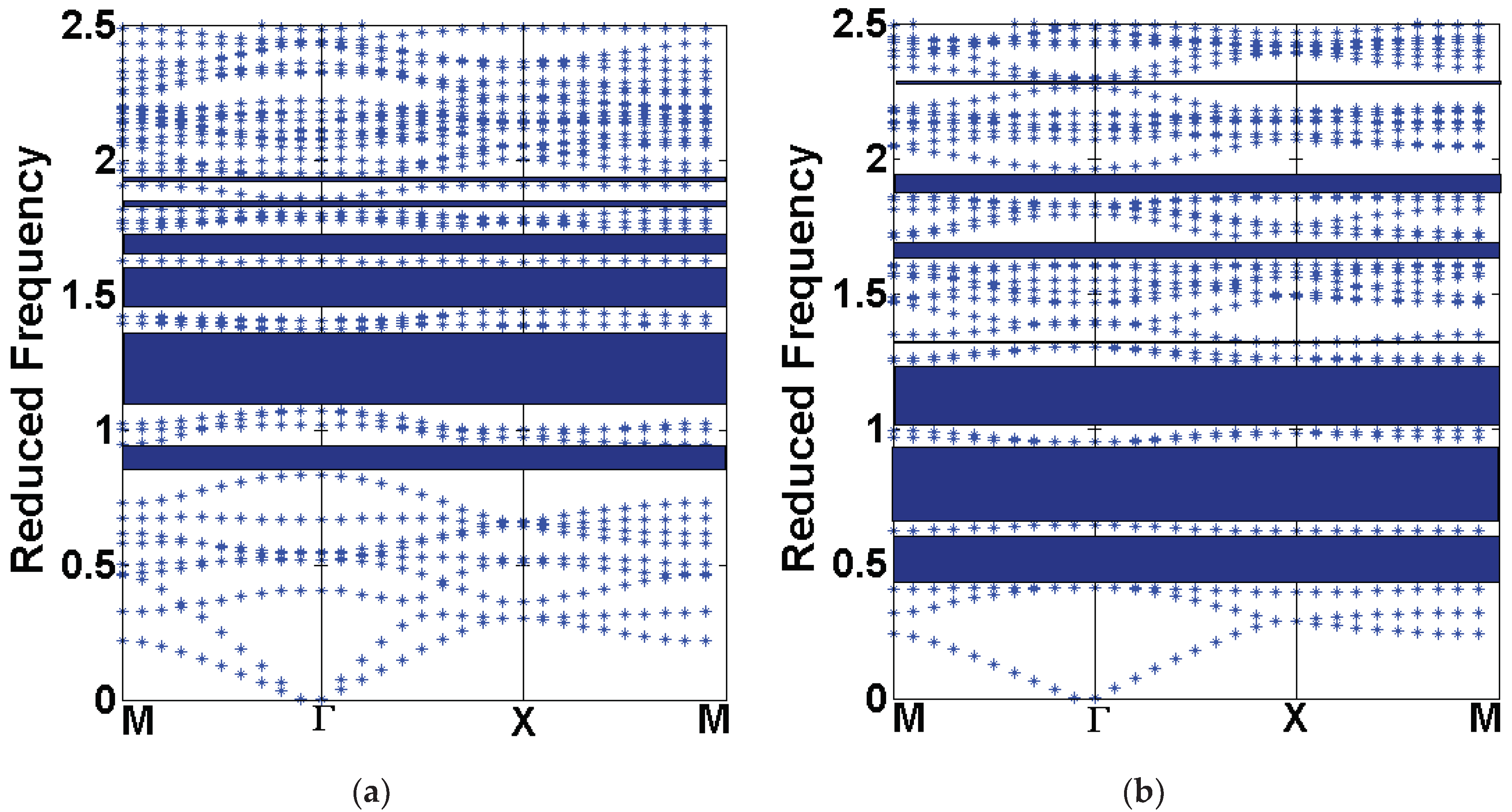
We computed the dispersion diagram considering first a fixed filling fraction, 0.5, for circular scatterers in a Kagomé lattice. We regarded 441 plane waves for Fourier series expansion, which resulted in a good convergence for the IPWE results. Dispersion diagram plots were limited until a maximum normalized frequency, Ω = ω a / 2 π c t , of 2.5, where ω is the angular frequency and c t = c 44 B / ρ B is the transverse wave velocity in the polymeric matrix. Figure 2a,b show the dispersion diagrams of the MPnC with circular scatterers and Kagomé lattice, regarding the XY modes (a) and Z modes without piezoelectricity and piezomagnetism (b).
We plotted the dispersion diagrams in the principal symmetry directions of FIBZ (see Figure 1b). Plots are given in terms of the reduced frequency versus the reduced Bloch wave vector, k ¯ = k a / 2 π , where k is the Bloch wave vector.
Figure 2 shows six (a) and seven (b) complete Bragg-type band gaps until the reduced frequency of 2.5. One can observe that these results for XY modes (a) and Z modes without piezoelectricity and piezomagnetism (b) are different from the results of Wang et al. [11]. This is mainly associated with the higher convergence of IPWE method and the correct expressions of reciprocal lattice vector and structure function for Kagomé lattice.
In Figure 3, we illustrate the dispersion diagram comparison of the Z modes without piezoelectricity and piezomagnetism (blue asterisks in (a–c)), Z modes with piezoelectricity (red circles in (a)), Z modes with piezomagnetism (red circles in (b)), and Z modes with both piezoelectric and piezomagnetic effects (red circles in (c)).
The Z modes with piezo effects (red circles in (a–c)) were shifted to higher frequencies in relation to the Z modes without piezo effects (blue asterisks in (a–c)). Therefore, the band gaps were also shifted to higher frequencies considering the piezo effects. The Z modes with only piezoelectric effect (a) presented a behaviour close to Z modes with both piezoelectric and piezomagnetic effects (c). Moreover, the Z modes with only piezomagnetic effect (b) appeared in lower frequencies than Z modes with only piezoelectric effect (a) and with both piezoelectric and piezomagnetic effects (c) [10,15].
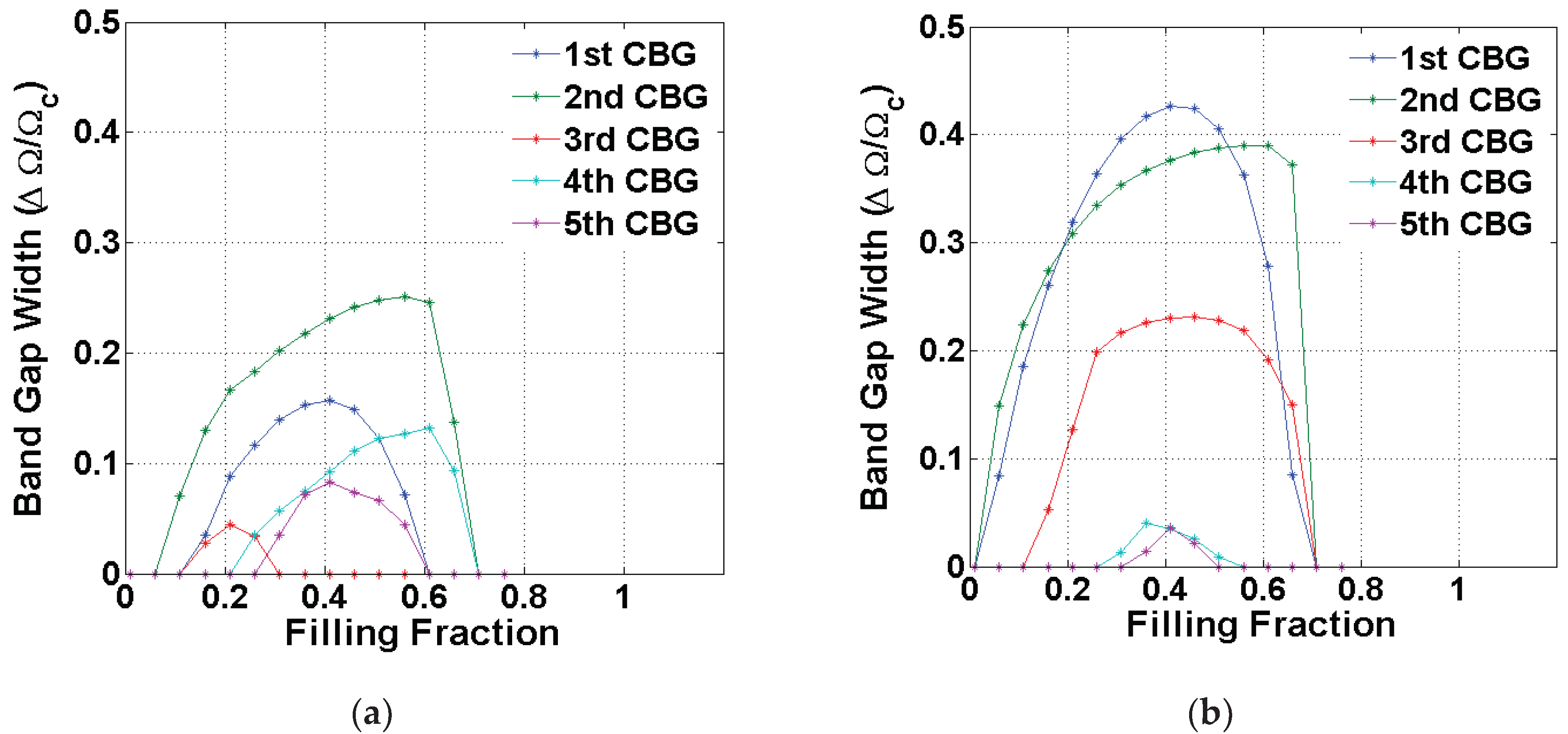
We show, in Figure 4, the complete band gap widths (only for the first five band gaps) between XY modes (a) and Z modes without piezo effects (b) as a function of filling fraction for circular scatterers and Kagomé lattice. Note that Ω c is the central normalized frequency of the band gap.
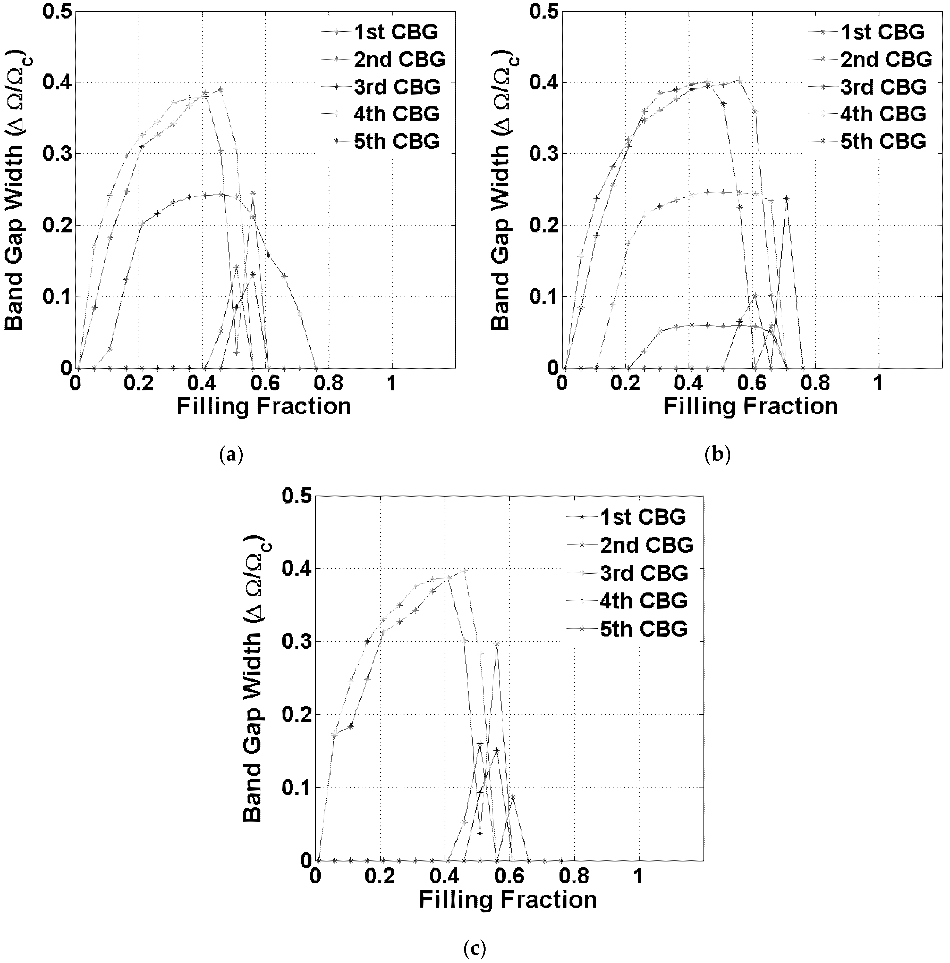
The results in Figure 4 are quite different from that those reported by Wang et al. [11]. The band gap widths of the Z modes (b) were higher than the XY modes (a) and were opened in a broad range of filling fraction. We illustrate, in Figure 5, the complete band gap widths (only for the first five band gaps) between Z modes with piezoelectricity (a), Z modes with piezomagnetism (b), and Z modes with both piezo effects (c) as a function of filling fraction for circular scatterers and Kagomé lattice. Wang et al. [11] did not investigate the effect of only piezoelectric (a) and piezomagnetic (b) effects on the band gap width.
The band gap widths considering the Z modes with piezo effects, Figure 5c, showed a similar behaviour to the Z modes with only piezoelectric effect, Figure 5a, except for the third band gap, which was broader for Z modes with only piezoelectric effect, Figure 5a. The band gap widths for the Z modes with only piezomagnetism, Figure 5b, presented an interesting behaviour, since the band gap widths were higher and opened for a broader range of frequency than the other cases, Figure 5a,c. The physical characteristics related to Figure 5a–c should be better understood in future studies by means of the experimentation.

4. Conclusions

The dispersion diagram of a MPnC was investigated considering circular scatterers and Kagomé lattice by means of the IPWE. This approach may be useful for modelling smart PnCs, such as piezoelectric and/or piezomagnetic PnCs, piezoelectric periodic structures with resonant shunting circuits, and adaptive mechanical metamaterials with circuits. We compared the results of the IPWE approach with Wang et al. [11]. Major differences were observed, and they can be associated with the fact that we used the IPWE approach (which shows high Fourier series convergence) and the correct expressions of reciprocal lattice vector and structure function for Kagomé lattice, whereas Wang et al. [11] used the traditional PWE and the expressions for square lattice. The influence of piezoelectric and piezomagnetic effects on the Z modes was significant on the band gap widths and localizations. We suggest that the complete Bragg-type band gaps in MPnCs enlarge the applications for mechanical vibration management.

Author Contributions

Conceptualization, E.J.P.d.M.J. and J.M.C.D.S.; methodology, E.J.P.d.M.J., S.F.R., C.A.J., E.S.S., G.S.R., and A.E.M.P.; simulation, E.J.P.d.M.J. and H.V.C.d.S.; writing—original draft preparation, E.J.P.d.M.J., S.F.R., and J.M.C.D.S. All authors have read and agreed to the published version of the manuscript.

Funding

This research was funded by Natural Sciences and Engineering Research Council of Canada (NSERC), Canada Foundation for Innovation (CFI), New Brunswick Innovation Foundation (NBIF), Harrison McCain Foundation, FAPEMA, FAPESP grant number 2018/15894-0, CNPq grant numbers 140783/2017-2 and 313620/2018-0.

Conflicts of Interest

The authors declare no conflict of interest.

References

  1. Sigalas, M.M.; Economou, E.N. Elastic and acoustic wave band structure. J. Sound Vib. 1992, 158, 377–382. [Google Scholar] [CrossRef]
  2. Kushwaha, M.S.; Halevi, P.; Martínez, G.; Dobrzynski, L.; Djafari-Rouhani, B. Theory of acoustic band structure of periodic elastic composites. Phys. Rev. B Condens. Matter 1994, 49, 2313–2322. [Google Scholar] [CrossRef] [PubMed]
  3. Tian, Z.; Shen, C.; Li, J.; Reit, E.; Bachman, H.; Socolar, J.E.S.; Cummer, S.A.; Huang, T.J. Dispersion tuning and route reconfiguration of acoustic waves in valley topological phononic crystals. Nat. Commun. 2020, 11, 1–10. [Google Scholar] [CrossRef] [PubMed] [Green Version]
  4. Qian, D. Electro-mechanical coupling wave propagating in a locally resonant piezoelectric/elastic phononic crystal nanobeam with surface effects. Appl. Math. Mech. 2020, 41, 425–438. [Google Scholar] [CrossRef]
  5. Chen, Z.-G.; Zhao, J.; Mei, J.; Wu, Y. Acoustic frequency filter based on anisotropic topological phononic crystals. Sci. Rep. 2017, 7, 1–6. [Google Scholar] [CrossRef] [Green Version]
  6. Gkantzounis, G.; Florescu, M. Freeform phononic waveguides. Crystals 2017, 7, 353. [Google Scholar] [CrossRef] [Green Version]
  7. Rezaei, S.; Eskandari-Ghadi, M.; Rahimian, M. Simulation-based conceptual design of an acoustic metamaterial with full band gap using an air-based 1-3 piezoelectric composite for ultrasonic noise control. C. R. Mec. 2017, 345, 137–152. [Google Scholar] [CrossRef]
  8. Miranda, E.J.P., Jr.; Dos Santos, J.M.C. Complete band gaps in nano-piezoelectric phononic crystals. Mat. Res. 2017, 20 (Suppl. 1), 15–38. [Google Scholar] [CrossRef] [Green Version]
  9. Vasseur, J.O.; Matar, O.B.; Robillard, J.F.; Hladky-Hennion, A.-C.; Deymier, P.A. Band structures tunability of bulk 2D phononic crystals made of magneto-elastic materials. AIP Adv. 2011, 1, 041904–041915. [Google Scholar] [CrossRef] [Green Version]
  10. Wang, Y.-Z.; Li, F.-M.; Huang, W.-H.; Jiang, X.; Wang, Y.-S.; Kishimoto, K. Wave band gaps in two-dimensional piezoelectric/piezomagnetic phononic crystals. Int. J. Solids Struct. 2008, 45, 4203–4210. [Google Scholar] [CrossRef] [Green Version]
  11. Wang, Y.-Z.; Li, F.-M.; Kishimoto, K.; Wang, Y.-S.; Huang, W.-H. Band gap behaviours of periodic magnetoelectroelastic composite structures with Kagome lattices. Waves Random Complex Media 2009, 19, 509–520. [Google Scholar] [CrossRef]
  12. Wang, Y.-Z.; Li, F.-M.; Kishimoto, K.; Wang, Y.-S.; Huang, W.-H. Elastic wave band gaps in magnetoelectroelastic phononic crystals. Wave Motion. 2009, 46, 47–56. [Google Scholar] [CrossRef]
  13. Wang, Y.-Z.; Li, F.-M. Band gap properties of magnetoelectroelastic grid structures with initial stress. Chin. Phys. Lett. 2012, 29, 034301–034311. [Google Scholar] [CrossRef]
  14. Guo, X.; Wei, P.; Lan, M.; Li, L. Dispersion relations of elastic waves in one-dimensional piezoelectric/piezomagnetic phononic crystal with functionally graded interlayers. Ultrasonics 2016, 70, 158–171. [Google Scholar] [CrossRef]
  15. Miranda, E.J.P., Jr.; Dos Santos, J.M.C. Evanescent Bloch waves and complex band structure in magnetoelectroelastic phononic crystals. Mech. Syst. Signal Pr. 2018, 112, 280–304. [Google Scholar] [CrossRef]
  16. Hutchinson, R.G.; Fleck, N.A. The structural performance of the periodic truss. J. Mech. Phys. Solids 2006, 54, 756–782. [Google Scholar] [CrossRef]
  17. Souslov, A.; Liu, A.J.; Lubensky, T.C. Elasticity and response in nearly isostatic periodic lattices. Phys. Rev. Lett. 2009, 103, 205503–205506. [Google Scholar] [CrossRef] [Green Version]
  18. Sun, K.; Souslov, A.; Mao, X.; Lubensky, T.C. Surface phonons, elastic response, and conformal invariance in twisted kagome lattices. Proc. Natl. Acad. Sci. USA 2012, 109, 12369–12374. [Google Scholar] [CrossRef] [Green Version]
  19. Riva, E.; Quadrelli, D.E.; Cazzulani, G.; Braghin, F. Tunable in-plane topologically protected edge waves in continuum Kagome lattices. J. Appl. Phys. 2018, 124, 164903–164912. [Google Scholar] [CrossRef]
  20. Ghimire, N.J.; Mazin, I.I. Topology and correlations on the kagome lattice. Nat. Mater. 2020, 19, 137–138. [Google Scholar] [CrossRef]
  21. Cao, Y.; Hou, Z.; Liu, Y. Convergence problem of plane-wave expansion method for phononic crystals. Phys. Lett. A 2004, 327, 247–253. [Google Scholar] [CrossRef]
  22. Dyogtyev, A.V.; Sukhoivanov, I.A.; De La Rue, R.M. Photonic band-gaps maps for different two dimensionally periodic photonic crystal structures. J. Appl. Phys. 2010, 107, 013108–0131114. [Google Scholar] [CrossRef]
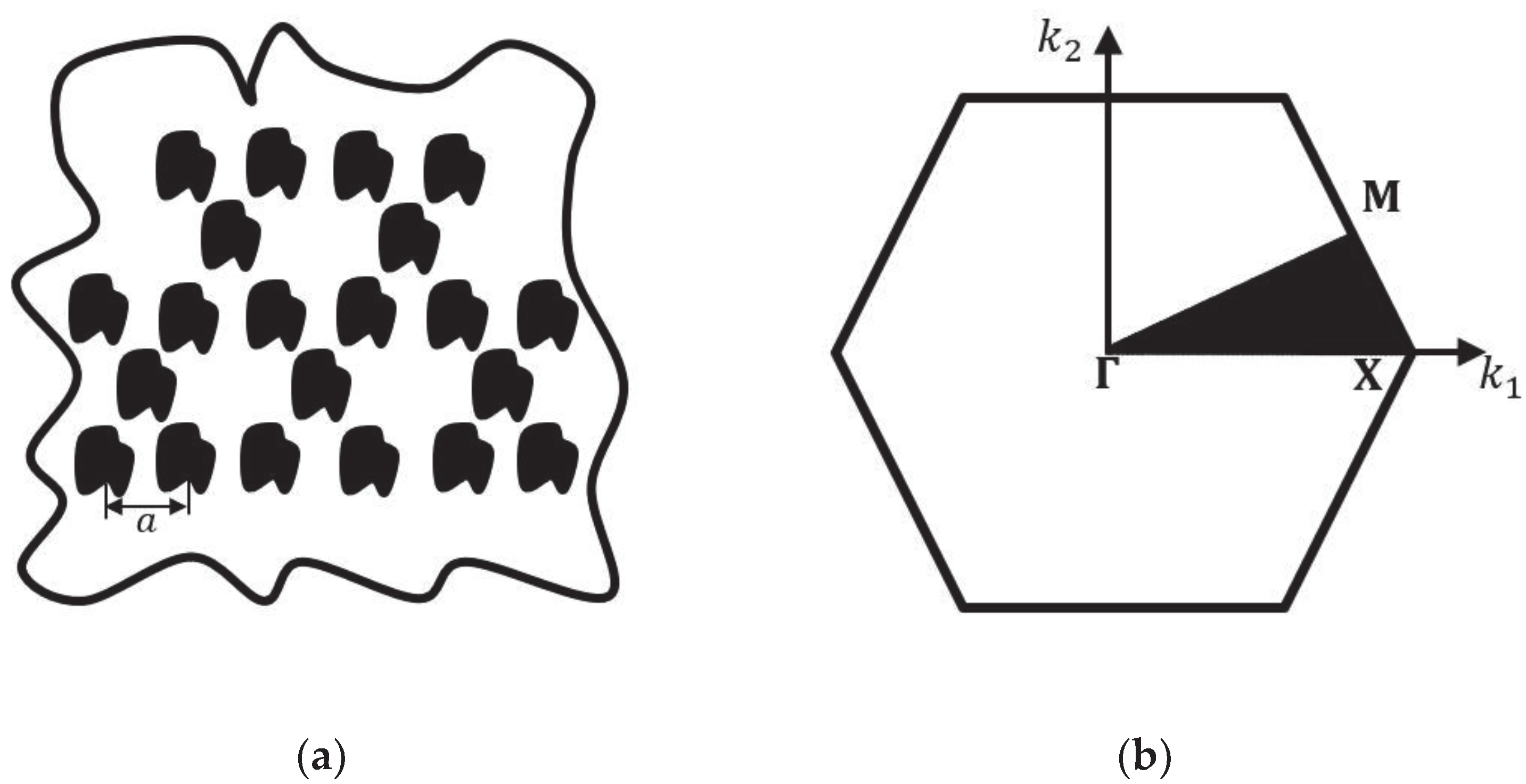
Figure 1. Transverse cross section area of the magnetoelectroelastic phononic crystal (MPnC) with Kagomé lattice (a). First irreducible Brillouin zone for Kagomé lattice (b).
Crystals 10 00586 g001
Figure 2. Dispersion diagrams of the MPnC with circular scatterers and Kagomé lattice, considering XY modes (a) and Z modes without piezoelectricity and piezomagnetism (b) for f = 0.5. The shaded regions are the complete Bragg-type band gaps.
Crystals 10 00586 g002
Figure 3. Dispersion diagram comparison of the MPnC with circular scatterers and Kagomé lattice for f = 0.5, considering Z modes without piezoelectricity and piezomagnetism (blue asterisks in (ac)), Z modes with piezoelectricity (red circles in (a)), Z modes with piezomagnetism (red circles in (b)), and Z modes with piezoelectricity and piezomagnetism (red circles in (c)).
Crystals 10 00586 g003
Figure 4. Complete band gap widths of the MPnC with circular scatterers and Kagomé lattice, considering XY modes (a) and Z modes without piezoelectric and piezomagnetic effects (b).
Crystals 10 00586 g004
Figure 5. Complete band gap widths of the MPnC with circular scatterers and Kagomé lattice, considering Z modes with piezoelectricity (a), Z modes with piezomagnetism (b), and Z modes with piezoelectricity and piezomagnetism (c).
Crystals 10 00586 g005
Table 1. Physical parameters of BaTiO3–CoFe2O4 scatterers (A) and a polymeric matrix (B).
Geometry/PropertyValue
Lattice parameter ( a ) 0.022 m
Filling fraction ( f ) 0.5
Mass density ( ρ A , ρ B )5730 kg/m3, 1150 kg/m3
Elastic constant ( c 11 A , c 11 B ) 166 × 109 N/m2, 7.8 × 10⁹ N/m2
Elastic constant ( c 12 A , c 12 B ) 77 × 109 N/m2, 4.7 × 10⁹ N/m2
Elastic constant ( c 44 A , c 44 B ) 43 × 109 N/m2, 1.6 × 10⁹ N/m2
Elastic constant ( c 66 A , c 66 B ) 44.5 × 10⁹ N/m2, 1.55 × 10⁹ N/m2
Piezoelectric coefficient ( e 15 A , e 15 B ) 11.6 C/m2, 0 C/m2
Dielectric coefficient ( ϵ 11 A , ϵ 11 B ) 11.2 × 10⁻⁹ C2/Nm2, 0.0398 × 10⁻⁹ C2/Nm2
Piezomagnetic coefficient ( q 15 A , q 15 B ) 550 N/Am, 0 N/Am
Magnetic permeability coefficient ( Γ 11 A , Γ 11 B )5 × 10⁻⁶ Ns2/C2, 5 × 10⁻⁶ Ns2/C2
Electromagnetic coefficient ( λ 11 A , λ 11 B )0.005 × 10⁻⁹ Ns/VC, 0 Ns/VC