Article

Effect of Internal Radiation on Process Parameters in the Global Simulation of Growing Large-Size Bulk β-Ga2O3 Single Crystals with the Czochralski Method

The Institute of Technological Sciences, Wuhan University, Wuhan 430072, China
*
Author to whom correspondence should be addressed.
Crystals 2021, 11(7), 763; https://doi.org/10.3390/cryst11070763
Submission received: 5 June 2021 / Revised: 24 June 2021 / Accepted: 25 June 2021 / Published: 29 June 2021

Abstract

:
As a crystal grows, the temperature distribution of the crystal and melt will change. It is necessary to study the dynamic process of single-crystal growth. Due to the relatively low crystallization rates used in the industrial Czochralski growth system, a steady state is used to compute the temperature distribution and melt flow. A two-dimensional axisymmetric model of the whole Czochralski furnace was established. The dynamic growth process of large-size bulk β-Ga2O3 single crystal using the Czochralski method has been numerically analyzed with the parameter sweep method. In this paper, two cases of internal radiation and no internal radiation were compared to study the effect of radiation on the process parameters. The temperature distribution of the furnace, the temperature field, and the flow field of the melt was calculated. The temperature, the temperature gradient of the crystal, the temperature at the bottom of the crucible, and the heater power were studied for the crystals grown in the two cases of radiation. The results obtained in this study clearly show that the loss calculated by including the internal radiation is higher compared to that including the surface radiation.

1. Introduction

Gallium oxide has five polymorphisms, and other phases transform into the β phase at high temperatures. β-Ga2O3 is the most stable crystal structure, with a melting point of 1800 °C under atmospheric pressure [1,2]. Gallium oxide has a high electrical breakdown field and is an ideal material for the manufacture of high-power diodes. Gallium oxide can be used to manufacture various light-emitting diodes (LEDs) and laser diodes (LDs), new fluorescent materials, and gas sensors based on β-Ga2O3, as well as solar-blind UV detectors and high-temperature, high-frequency, and high-power electronics [3]. Gallium oxide has a good performance at high frequencies and high power and is an ideal material for power electronic equipment [4]. Gallium oxide has a wider band-gap than SiC and GaN, and its unique properties mean that it is used in many devices, including Schottky barrier diodes (SBDs), inverters equipment, circuits used in high-temperature, high-humidity and high-radiation environments, and field-effect transistors (FET) [5]. The application of β-Ga2O3 is expanding rapidly, and cost reduction for this method has become essential. One way to reduce cost is to increase the crystal diameter. However, enlarging the crystal diameter is quite difficult. The company Tamura has successfully prepared two-inch high-quality β-Ga2O3 single crystals using the edge-defined film-fed growth method [6]. Hoshikawa et al. used the vertical Bridgman (VB) method to successfully realize one-inch Ga2O3 single crystals. The crystal quality was good, without crucible pollution [7]. Galazka et al. [8] used the Czochralski method to grow β-Ga2O3 single crystals that were 2–3 inches in diameter. The melting temperature of gallium oxide is very high, and some materials are translucent to the near-infrared (NIR) wavelength range. In these materials, radiative heat transfer is more dominant than thermal transfer. As most oxide crystals have very large radiation losses, it is important to study radiation during growth [9]. The absorption coefficients of doped gallium oxide are different (4–100 cm−1). Crystals doped with Mg, Ce, and Al can be grown using the Czochralski method with a good quality, while doping with Cr and Si will lead to the spiral growth of crystals [10,11,12,13].
At present, the mechanism of spiral growth is not clear, and there are many explanations. The authors of [14,15] carried out three-dimensional time-dependent simulations and found that asymmetric temperature fields would cause periodic temperature oscillations. Spiral growth may be affected by asymmetric temperature distribution growth. Uecker [16] insisted that a reduction in radiant heat dissipation will flatten the radial temperature gradient in the melt near the interface, and increases the possibility of breaking symmetry. Enhancing the Marangoni flow also alleviates the formation of a spiral. Moreover, an increase in the radial temperature gradient (or the convexity of the growth interface) can inhibit spiral growth [17]. In addition, impurities and atmosphere affect optical absorption in the crystal and cylindrical growth stability [18,19]. The heat radiation from the iridium crucible reduces the radiant heat transfer through the crystal, resulting in spiral growth [20]. Some authors believed that the surface tension of the melt being reduced by impurities is the cause of spiral growth [21,22]. Schwabe disagreed with this view, believing that the two stages of spiral growth are caused by different reasons. The first stage may be caused by some external asymmetric thermal field, with the second stage of spiral growth being a kind of self-organization [23]. Galazka et al insisted β-Ga2O3 crystals have a tendency to a spiral formation due to free carrier absorption in the NIR wavelength range [10].
The Czochralski method was used to grow large-diameter single crystals of Ge and Si and some oxide crystals [24,25,26]. A small seed was dipped into the slightly overheated melt and pulled upwards from the melt. During the growth process, the crystal heating power, pulling rate, and rotation rate were carefully adjusted to control the shape of the crystal, especially the diameter. The automatic diameter control method for this crystal is called the crucible weighing method and was proposed by Kyle and Zydzik [27,28]. The crystal growth furnace for growing oxide crystals using the Czochralski method includes a heater, a puller, a pulling shaft connected to a weighing cell, a pulling/rotating motor, and a PID (proportional, integral, differential) controller computer. Miller [29] built a 2D global model for a crystal growth furnace to analyze the heat transport simulation and proceeded with 3D heat transport and fluid flow analysis on the basis of 2D simulation. Tang [30] established a 2-dimensional global model, analyzed the flow field and temperature field by steady-state simulation, and calculated the growth of the phase interface of different sizes by a transient method. In previous simulations, the steady-state calculations for a certain crystal length were studied and the effects of radiation in the medium were not taken into account. In this paper, dynamic modeling was used to analyze the effects of radiation on the process parameters during the whole growth process.

2. Simulation

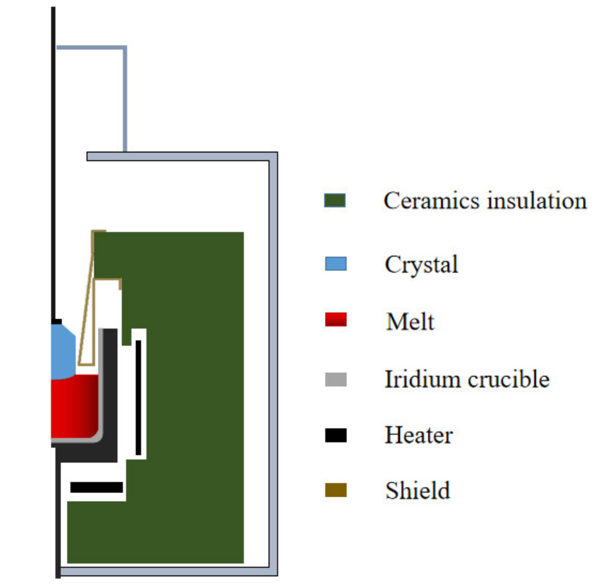
2.1. Geometric Model

Czochralski is one of the melt growth methods for large-size and high-quality β-Ga2O3 crystal growth, which has a low cost and a high crystal growth speed [31]. The geometry of Czochralski method is depicted in Figure 1. The growth furnace designed for β-Ga2O3 includes crucible support rods, crucible trays, heaters, shields, thermocouples, zirconia insulation ceramics, seed rods, and an iridium crucible and PID controller for automatic crystal diameter control. Zirconia ceramics are very good conductors at high temperatures, so in this model, resistance heating is used instead of electromagnetic induction heating. Gallium oxide melt is highly stable up to about 1200 °C and will decompose at high temperatures. Therefore, the Czochralski growth process requires a mixed atmosphere containing oxygen to inhibit the thermal decomposition of gallium oxide [32]. The growth chamber is the core of the growth furnace and consists of a metal crucible containing melt and insulated material surrounding the crucible. Crystals are pulled out from the crucible and an observation window (not shown) is on the side. After the raw material is melted, the directional seeds attached to the lifting shaft are dipped in the melt, and then slowly lifted while rotating. The seed diameter (usually a few millimeters) is then expanded to a pre-defined cylindrical diameter and grows at a constant rate of 1–5 mm/h. Once the cylinder reaches its final length, it is separated from the melt and slowly cooled to room temperature. The upper part of the furnace shell is supplied with cold air and the lower part with cooling water. From an engineering point, the Czochralski method is a dynamic phase transition problem with internal moving boundaries and free surface, including heat transfer by the melt and ambient, internal radiation in the crystal, surface-to-surface radiation between the boundaries and ambient, flow and heat transfer coupling in the melt and phase transition in the solid–liquid interface.

2.2. Mathematical Model

This model provides a solution to the axisymmetric heat transfer problem that accounts for the heat transfer via conduction and heat exchange between solid surfaces by radiation. The melt flow effect can also be accounted for in the model. The convection heat transfers in the melt and gas are included. The surface-to-surface radiation between the boundaries and ambient and heat exchange via convection are calculated. As using the P1 method can significantly reduce the calculation cost, this method is used to solve the 3-dimensional internal radiation problem in the crystal medium with emission and absorption. The steady state is applied to compute the furnace temperature, phase interface, and flow field during crystal growth using the with parameter sweep method [33]. The model is established with parameters. The crucible moves upward and the melt quality decreases as the crystal length changes. By scanning the parameter of crystal length, there is no need to modify the geometry manually, and a steady-state calculation can be carried out for each scanning.
The following assumptions are made to simplify the model:
(1)
The crystal is fully cylindrical and isotropic
(2)
The melt is considered as an incompressible liquid. The temperature field in the crucible is axially symmetric.
(3)
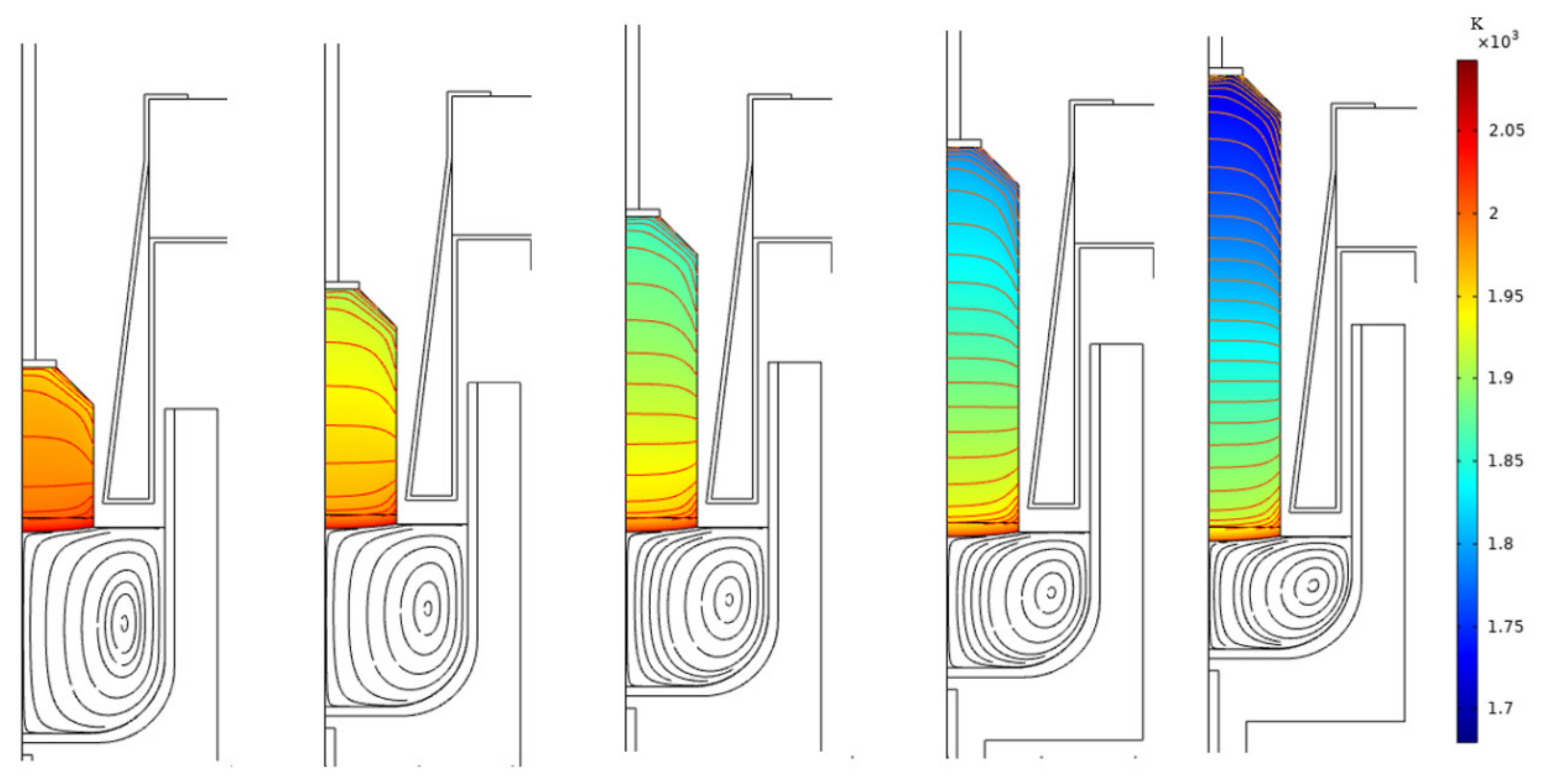
Due to the relatively low crystallization rates (2 mm/h), the growing process can be seen as quasi-static.
(4)
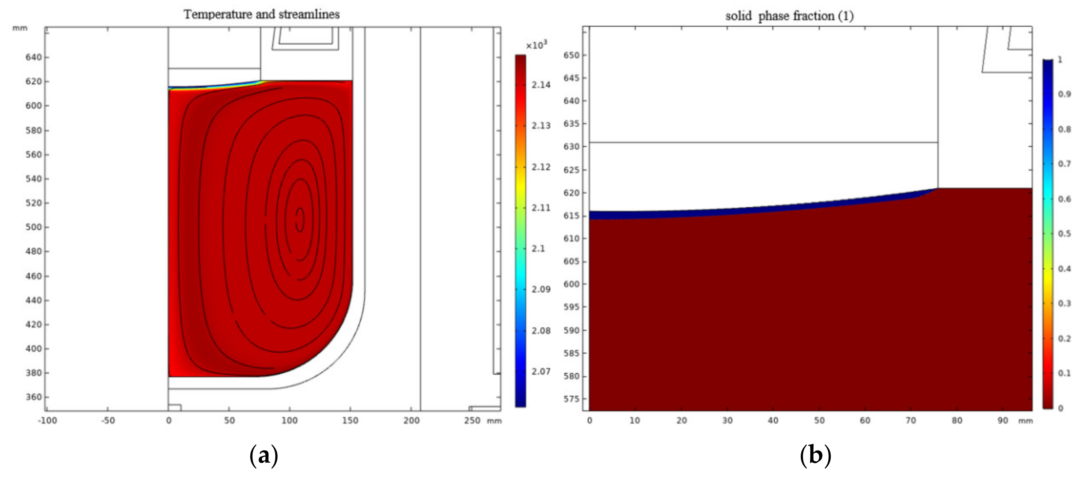
The phase interface shape has little effect on the overall temperature distribution and heater power. It is convex over the entire growth process with slight changes slightly in thickness. Therefore, at this stage, we have neglected the changes in the phase interface.

2.2.1. Thermophysical Properties

The thermophysical properties of the Ga2O3 melt are given in Table 1.

2.2.2. The Actual Governing Equations of the Model

The heat transfer is described by the following equation [40]:
ρ c P u     T +   k T = Q
The radiative portion of heat transfer is [41]:
n k T = ε G σ T 4 , 1 ε G = J ε σ T 4 ,
where k, Cp, and Q represent the thermal conductivity, the specific heat capacity of the material, and the external heating source, respectively. ε is the emissivity, G is the irradiation, σ is called the blackbody radiation constant, and J is radiosity. According to the following equation, the liquid portion is described by the fluid velocity u and pressure p to simulate the laminar flow. The governing equations are as follows [42]:
ρ u t + u u = P + µ u + u T p I + ρ g , ρ t + ρ u = 0 ,
where ρ denotes the density and µ is the viscosity. For an axisymmetric flow, the equations reduce to:
ρ u u r ν 2 r + ω u z + P r = μ 1 r r r u r u r 2 + 2 u z 2 + F r , ρ u ν r + u ν r + ω ν z = μ 1 r r r ν r ν r 2 + 2 ν z 2 + F φ , ρ u ω r + ω ω z + P z = μ 1 r r r ω r + 2 ω z 2 + F z .
Here, u is the radial velocity, υ is the rotational velocity, and ω is the axial angular velocity. In the model, Fr and F φ are 0.
Different from reference [30], we added the phase material module into the heat transfer calculation. In the module, the phase transition temperature, phase transition interval, and latent heat were set. The solid fraction (the ratio of solid mass to the sum of solid and liquid mass) was used to represent the solidification degree of the melt in the phase transformation zone. For example, the solid fraction of solid is 1, the liquid fraction is 0, and the material in the transition interval is 0–1.
When the crystal is pulled out from the melt, the volume of melt in the crucible decreases. In order to maintain a horizontal position in the phase interface, the crucible moves upward at a certain speed. The crucible rising rate is related to the pulling rate, which is derived by the mass conservation of the crystal and the melt.
ρ c r y × π r c r y 2 ν c r y = ρ m e l t × π r m e l t 2 ν m e l t ,
where ρ c r y denotes the crystal density, ρ m e l t denotes the melt density, and the crystal radius r c r y and melt radius r m e l t are known. ν c r y is set to 2 mm/h.

2.2.3. Mesh Model and Boundaries

The inner diameter of the crucible was 228 mm, the radius of the furnace was 780 mm, and the height was 1350 mm. There were 11,204 grids with 2478 elements in the melt. The seed was rotated at a speed of 2 rpm and the crystal and crucible rotate at a speed of 6 rpm in opposite directions. The sliding boundary condition was used on the seed and crucible and the axisymmetric boundary condition was adopted. The initial temperature in the system was set to be 300 K. Time iteration step was 0.1 s. Use adaptive mesh refinement and the minimum grid size was 2 mm.

2.3. Results and Discussion

The global temperature distribution and isotherms in the process system are shown in Figure 2. There are obvious high-temperature zones and cold zones in the furnace. When the temperature of the phase interface reached 1820 °C, the heather power was about 20 kW which corresponds to the actual situation. This means that the furnace structure and insulation accessories design were reasonable. Based on the accurate calculation of the whole temperature field, the coupling calculation of heat transfer and flow in the crucible was carried out, taking into account the natural convection. The temperature and velocity fields are given in Figure 3a. The solid–liquid interface was calculated by adding the phase change material into the heat transfer module, as shown in Figure 3b. The global simulation during the dynamic growth process is given in Figure 4. During the dynamic growth process, the crystal grows and the material mass decreased, while the relative position of the crucible and heater also changed. The relationship between the crystal growth rate and the crucible rising rate is given by Equation (5). In Figure 4, the surface-to-surface radiation is considered, excluding the internal radiation of the medium. The temperature gradient at the middle section is uniform and it is larger at the crystal shoulder, which agrees well with the reality. In this paper, the effects of the surface-to-surface radiation and the participating medium radiation on the temperature field and heater power are shown in Figure 5, Figure 6, Figure 7 and Figure 8. As shown in Figure 5, the trend of the heater power curve was completely different during crystal growth. The heater power, when considering the participating medium radiation, was higher than that when considering the surface to surface radiation as a whole. In the case of the surface to surface radiation, the heater power gradually decreased as the length of the crystal grew. This shows that crystal length increased the thermal resistance and reduces heat dissipation. If the participating medium radiation is considered, the power increased greatly with the increase in crystal length. The translucent crystal increases the heat dissipation of the furnace [14]. The power of the heater changed with the crystal growth and the temperature at the bottom of the crucible also changed. As shown in Figure 6, the temperatures at the bottom of the crucible almost stayed constant with the crystal growth in the case of surface-to-surface radiation. Meanwhile, when considering participating medium radiation, the temperature kept rising and the difference was about 60 K. The participating medium radiation has a greater influence on the bottom temperature. The participating medium radiation increased the heat flux at the solid–liquid interface and the temperature at the bottom of the crucible. The temperature at the bottom when considering the participating medium radiation is at least 30 K higher than that when considering the surface-to-surface radiation as a whole. The participating medium radiation of the crystal also has a great influence on the temperature distribution and temperature gradient. In the process of growth, the working point and dynamic characteristics of CZ systems will change permanently. Due to this situation and the nonlinear characteristics of the CZ system, the practicability of a linear PID controller is limited. This is especially true for growing opaque oxide crystals with a large diameter. This problem can be solved using empirical parameters. However, changes in the thermal environment or the enlargement of the diameter necessitate extraordinary effort to be made to adjust all experimental parameters. Figure 5 and Figure 6 are helpful to understand the variation of power and the temperature at the bottom. As shown in Figure 7 and Figure 8, when considering participating medium radiation, the temperature gradient of the crystal is lower than that in the case of the surface-to-surface radiation. The temperature gradient is uniform in the middle of the crystal and higher at the shoulder of the crystal. The temperature gradient drops from 20 K/cm to 5 K/cm. In the case of the participating medium radiation, the temperature gradient difference between the middle section and shoulder is larger. It is necessary to improve the thermal radiation of the crystal shoulder to reduce the temperature gradient and make the temperature gradient of the crystal more uniform.

3. Conclusions

In this paper, two models of surface radiation and internal radiation are compared to study the effect of radiation on the process parameters. The power and temperature trajectories at the bottom of the crucible are obtained. The temperature distribution of the furnace, the temperature field, and the flow field of the melt are calculated. The temperature, the temperature gradient of the crystal, the temperature at the bottom of the crucible, and the heater power are studied when the crystal is growing in the two cases of radiation. The results are helpful to adjust the parameters for use in industry. The results obtained in this study show that the participating medium radiation has a great influence on the power and temperature trajectories. The internal radiation influences the dynamic characteristics of CZ systems and reduces the temperature gradient of the crystal.

Author Contributions

Conceptualization, X.T. and B.G.; methodology, X.T.; software, B.L.; validation, S.L., Y.Y. and X.T.; formal analysis, Y.Y. and B.S.; investigation, B.L. and P.H.; supervision, B.G. All authors have read and agreed to the published version of the manuscript.

Funding

This research received no external funding.

Institutional Review Board Statement

Not applicable.

Informed Consent Statement

Not applicable.

Data Availability Statement

Exclude this statement.

Conflicts of Interest

The authors declare no conflict of interest.

Nomenclature

Cpthe Specific Heat Capacity
Frforce in r direction
F φ force in the circumferential direction
F z force in z-direction
Girradiation
Jradiosity
kthermal conductivity
ppressure
Qexternal heating source
rradial coordinate of the melt/crystal
Ttemperature
ufluid velocity
εemissivity
υrotational velocity
ωaxial angular velocity
ρdensity
µviscosity
σblackbody radiation constant

References

  1. Fornari, R.; Pavesi, M.; Montedoro, V.; Klimm, D.; Mezzadri, F.; Cora, I.; Pécz, B.; Boschi, F.; Parisinia, A.; Baraldi, A.; et al. Thermal stability of ε-Ga2O3 polymorph. Acta Mater. 2017, 140, 411–416. [Google Scholar] [CrossRef]
  2. Lee, S.D.; Akaiwa, K.; Fujita, S. Thermal stability of single crystalline alpha gallium oxide films on sapphire substrates. Phys. Status Solidi (c) 2013, 10, 1592–1595. [Google Scholar] [CrossRef]
  3. Kim, M.; Seo, J.-H.; Singisetti, U.; Ma, Z. Recent advances in free-standing single crystalline wide band-gap semiconductors and their applications: GaN, SiC, ZnO, β-Ga2O3, and diamond. J. Mater. Chem. C 2017, 5, 8338–8354. [Google Scholar] [CrossRef]
  4. Mastro, M.A.; Kuramata, A.; Calkins, J.; Kim, J.; Ren, F.; Pearton, S. Perspective—opportunities and future directions for Ga2O3. ECS J. Solid State Sci. Technol. 2017, 6, P356–P359. [Google Scholar] [CrossRef]
  5. Sasaki, K.; Higashiwaki, M.; Kuramata, A.; Masui, T.; Yamakoshi, S. MBE grown Ga2O3 and its power device applications. J. Cryst. Growth 2013, 378, 591–595. [Google Scholar] [CrossRef]
  6. β-Ga2O3 Substrates. Available online: http://www.tamura-ss.co.jp/en/products/gao/index.html (accessed on 1 July 2020).
  7. Hoshikawa, K.; Ohba, E.; Kobayashi, T.; Yanagisawa, J.; Miyagawa, C.; Nakamura, Y. Growth of beta-Ga2O3 single crystals using vertical bridgman method in ambient air. J. Cryst. Growth 2016, 447, 36–41. [Google Scholar] [CrossRef]
  8. Galazka, Z.; Uecker, R.; Irmscher, K.; Albrecht, M.; Klimm, D.; Pietsch, M.; Brützam, M.; Bertram, R.; Ganschow, S.; Fornari, R. Czochralski growth and characterization of β-Ga2O3 single crystals. Cryst. Res. Technol. 2010, 45, 1229–1236. [Google Scholar] [CrossRef]
  9. Banerjee, J.; Muralidhar, K. Role of internal radiation during czochralski growth of YAG and Nd: YAG crystals. Int. J. Therm. Sci. 2006, 45, 151–167. [Google Scholar] [CrossRef]
  10. Galazka, Z.; Irmscher, K.; Uecker, R.; Bertram, R.; Pietsch, M.; Kwasniewski, A.; Naumann, M.; Schulz, T.; Schewski, R.; Klimm, D.; et al. On the bulk β-Ga2O3 single crystals grown by the czochralski method. J. Cryst. Growth 2014, 404, 184–191. [Google Scholar] [CrossRef]
  11. Galazka, Z.; Uecker, R.; Klimm, D.; Irmscher, K.; Naumann, M.; Pietsch, M.; Kwasniewski, A.; Bertram, R.; Ganschow, S.; Bickermann, M. Scaling-up of bulk β-Ga2O3 single crystals by the czochralski method. ECS J. Solid State Sci. Technol. 2016, 6, Q3007. [Google Scholar] [CrossRef]
  12. Galazka, Z.; Ganschow, S.; Fiedler, A.; Bertram, R.; Klimm, D.; Irmscher, K.; Schewski, R.; Pietsch, M.; Albrecht, M.; Bickermann, M. Doping of czochralski-grown bulk β-Ga2O3 single crystals with Cr, Ce and Al. J. Cryst. Growth 2018, 486, 82–90. [Google Scholar] [CrossRef]
  13. Galazka, Z. β-Ga2O3 for wide-bandgap electronics and optoelectronics. Semicond. Sci. Technol. 2018, 33, 113001. [Google Scholar] [CrossRef]
  14. Mihelčić, M.; Wingerath, K.; Pirron, C. Three-dimensional simulations of the czochralski bulk flow. J. Cryst. Growth 1984, 69, 473–488. [Google Scholar] [CrossRef]
  15. Kimura, H.; Numazawa, T.; Sato, M.; Maeda, H. Single crystal growth and characterization of (Dy1−xGdx)3Ga5O12 Garnets. J. Cryst. Growth 1988, 87, 523–528. [Google Scholar] [CrossRef]
  16. Uecker, R.; Wilke, H.; Schlom, D.; Velickov, B.; Reiche, P.; Polity, A.; Bernhagen, M.; Rossberg, M. Spiral formation during czochralski growth of rare-earth scandates. J. Cryst. Growth 2006, 295, 84–91. [Google Scholar] [CrossRef]
  17. Fei, Y.; Chou, M.M.; Chai, B.H. Crystal growth and morphology of substituted gadolinium gallium garnet. J. Cryst. Growth 2002, 240, 185–189. [Google Scholar] [CrossRef]
  18. Brandle, C.; Fratello, V.; Valentino, A.; Stokowski, S. Effects of impurities and atmosphere on the growth of Cr-doped gadolinium scandium gallium garnet. I. J. Cryst. Growth 1987, 85, 223–228. [Google Scholar] [CrossRef]
  19. Fratello, V.; Brandle, C.; Valentino, A.; Stokowski, S. Effects of impurities and atmosphere on the growth of Cr-doped gadolinium scandium gallium garnet. II. J. Cryst. Growth 1987, 85, 229–233. [Google Scholar] [CrossRef]
  20. Okano, Y.; Ikeya, T.; Hoshikawa, K.; Fukuda, T. Behavior of RAlO3 (R=Ho, Er and Dy) during crystal growth by the Czochralski method. J. Cryst. Growth 1993, 131, 616–619. [Google Scholar] [CrossRef]
  21. Kochurikhin, V.; Shimamura, K.; Fukuda, T. Investigation of spiral bending of straight Czochralski grown dysprosium gallium aluminium garnet crystals. J. Cryst. Growth 1996, 160, 181–183. [Google Scholar] [CrossRef]
  22. Kochurikhin, V.; Shimamura, K.; Fukuda, T. The influence of dopants on the interface stability during Dy3Ga5O12 single crystal growth. J. Cryst. Growth 1994, 143, 232–236. [Google Scholar] [CrossRef]
  23. Schwabe, D.; Uecker, R.; Bernhagen, M.; Galazka, Z. An analysis of and a model for spiral growth of czochralski-grown oxide crystals with high melting point. J. Cryst. Growth 2011, 335, 138–147. [Google Scholar] [CrossRef]
  24. Czochralski, J. Ein neues verfahren zur messung der kristallisationsgeschwindigkeit der metalle. Z. Phys. Chem. 1918, 92, 219–221. [Google Scholar] [CrossRef]
  25. Teal, G.K.; Little, J.B. Growth of germanium single crystals. One physics ellipse, college PK, MD 20740-3844 USA: American Physical Soc. Phys. Rev. 1950, 78, 647. [Google Scholar]
  26. Nassau, K.; van Uitert, L.G. Preparation of large calcium-tungstate crystals containing paramagnetic ions for maser applications. J. Appl. Phys. 1960, 31, 1508. [Google Scholar] [CrossRef]
  27. Bardsley, W.; Green, G.W.; Holliday, C.H.; Hurle, D.T.J. Automatic control of czochralski crystal growth. J. Cryst. Growth 1972, 16, 277–279. [Google Scholar] [CrossRef]
  28. Kyle, T.R.; Zydzik, G. Automated crystal puller. Mater. Res. Bull. 1973, 8, 443–450. [Google Scholar] [CrossRef]
  29. Miller, W.; Böttcher, K.; Galazka, Z.; Schreuer, J. Numerical modelling of the czochralski growth of β-Ga2O3. Crystals 2017, 7, 26. [Google Scholar] [CrossRef] [Green Version]
  30. Tang, X.; Liu, B.; Yu, Y.; Liu, S.; Gao, B. Numerical analysis of difficulties of growing large-size bulk β-Ga2O3 single crystals with the Czochralski Method. Crystals 2021, 11, 25. [Google Scholar] [CrossRef]
  31. Galazka, Z. Czochralski method. In Gallium Oxide; Higashiwaki, M., Fujita, S., Eds.; Springer Series in Materials Science; Springer: Cham, Switzerland, 2020; Volume 293. [Google Scholar] [CrossRef]
  32. Jackson, A.J.; Walsh, A. Oxidation of GaN: An ab initio thermodynamic approach. Phys. Rev. B 2013, 88. [Google Scholar] [CrossRef] [Green Version]
  33. Zhao, Y.; Niu, S.; Ho, S.L.; Fu, W.N.; Zhu, J. A parameterized mesh generation and refinement method for finite element parameter sweeping analysis of electromagnetic devices. IEEE Trans. Magn. 2012, 48, 239–242. [Google Scholar] [CrossRef]
  34. Nikolaev, V.I.; Stepanov, S.I.; Romanov, A.E.; Bougrov, V.E. Single crystals of electronic materials growth and properties. In Electronic and Optical Materials; Woodhead Publishing: Sawston, Britain, 2019; pp. 487–521. [Google Scholar]
  35. Srivastava, R.D.; Farber, M. Thermodynamic properties of group 3 oxides. Chem. Rev. 1978, 78, 627–638. [Google Scholar] [CrossRef]
  36. Derby, J.J.; Xiao, Q. Some effects of crystal rotation on large-scale czochralski oxide growth: Analysis via a hydrodynamic thermal-capillary model. J. Cryst. Growth 1991, 113, 575–586. [Google Scholar] [CrossRef]
  37. Dingwell, D.B. Density of Ga2O3 liquid. J. Am. Ceram. Soc. 1992, 75, 1656–1657. [Google Scholar] [CrossRef] [Green Version]
  38. Santia, M.D.; Tandon, N.; Albrecht, J.D. Lattice thermal conductivity in β−Ga2O3 from first principles. Appl. Phys. Lett. 2015, 107. [Google Scholar] [CrossRef]
  39. Slomski, M.; Blumenschein, N.; Paskov, P.P.; Muth, J.F.; Paskova, T. Anisotropic thermal conductivity of β-Ga2O3 at elevated temperatures: Effect of Sn and Fe dopants. J. Appl. Phys. 2017, 121. [Google Scholar] [CrossRef]
  40. Voller, V.R.; Prakash, C. A fixed grid numerical modelling methodology for convection-diffusion mushy region phase-change problems. Int. J. Heat Mass Transf. 1987, 30, 1709–1719. [Google Scholar] [CrossRef]
  41. Yang, X.; Ma, W.; Lv, G.; Wei, K.; Luo, T.; Chen, D. A modified vacuum directional solidification system of multicrystalline silicon based on optimizing for heat transfer. J. Cryst. Growth 2014, 400, 7–14. [Google Scholar] [CrossRef]
  42. Gresho, P.M.; Sani, R.L. Incompressible Flow and the FInite Element Method. Volume 1: Advection-Diffusion and Isothermal Laminar Flow; John Wiley & Sons: Hoboken, NJ, USA, 1998; Volume 2, p. 469. [Google Scholar]
Figure 1. Scheme of the crystal growth furnace.
Crystals 11 00763 g001
Figure 2. Temperature distribution in the process system.
Crystals 11 00763 g002
Figure 3. (a) The temperature and velocity field; (b) the solid–liquid interface.
Crystals 11 00763 g003
Figure 4. Temperature field of the crystal during the dynamic growth process.
Crystals 11 00763 g004
Figure 5. Heater power during the dynamic growth process to help us consider the participating medium and the surface to surface radiation.
Crystals 11 00763 g005
Figure 6. Temperature at the crucible bottom during the dynamic growth process to help us consider the participating medium and the surface to surface radiation.
Crystals 11 00763 g006
Figure 7. The crystal temperature during the dynamic growth process to help us consider the participating medium and the surface to surface radiation.
Crystals 11 00763 g007
Figure 8. The crystal temperature gradient during the dynamic growth process to help us consider the participating medium and the surface to surface radiation.
Crystals 11 00763 g008
Table 1. Thermophysical properties, including optical data, of the β-Ga2O3 melt [29,32,34,35,36,37,38,39].
PropertySymbolMeltSolid
Densityρ (kg/m3)48005945
Specific heatCp (J/(kg·K))720560
Thermal conductivityλ (W/(m·K))521 at 300 K
7.83 at 2110 K
Viscosityµ (Ns/m2)0.1-
Reference temperatureTm1820 ± 10 °C
Thermal expansion coefficientβ (K−1) 6.4 × 10 4
Emissivityε0.3
EnthalpyΔH kJ/mol−1089
Absorption coefficient 4–100 (1/cm)
Refractive index 1.9
Publisher’s Note: MDPI stays neutral with regard to jurisdictional claims in published maps and institutional affiliations.

