Article

Formation Laws of Direction of Fano Line-Shape in a Ring MIM Plasmonic Waveguide Side-Coupled with a Rectangular Resonator and Nano-Sensing Analysis of Multiple Fano Resonances

1
National Key Laboratory of Tunable Laser Technology, Harbin Institute of Technology, Harbin 150001, China
2
College of Physics and Optoelectronic Engineering, Harbin Engineering University, Harbin 150001, China
*
Author to whom correspondence should be addressed.
Crystals 2021, 11(7), 819; https://doi.org/10.3390/cryst11070819
Submission received: 12 June 2021 / Revised: 8 July 2021 / Accepted: 10 July 2021 / Published: 14 July 2021
(This article belongs to the Special Issue Advances in Middle Infrared Laser Crystals and Its Applications)

Abstract

:
Plasmonic MIM (metal-insulator-metal) waveguides based on Fano resonance have been widely researched. However, the regulation of the direction of the line shape of Fano resonance is rarely mentioned. In order to study the regulation of the direction of the Fano line-shape, a Fano resonant plasmonic system, which consists of a MIM waveguide coupled with a ring resonator and a rectangle resonator, is proposed and investigated numerically via FEM (finite element method). We find the influencing factors and formation laws of the ‘direction’ of the Fano line-shape, and the optimal condition for the generation of multiple Fano resonances; and the application in refractive index sensing is also well studied. The conclusions can provide a clear theoretical reference for the regulation of the direction of the line shape of Fano resonance and the generation of multi Fano resonances in the designs of plasmonic nanodevices.

1. Introduction

Surface plasmon polaritons (SPPs) are transverse magnetic (TM)-polarized surface waves, which originate from interactions between incident photons and free electrons on metal (like silver and gold) surface and propagate along metal-dielectric interface. SPPs are bound to the metallic surface and decay exponentially in strength with respect to the distance away from the metal-dielectric interface in both directions and can overcome the diffraction limit and control the propagation of the optical signal at the nanoscale [1,2,3]. In recent times, numerous plasmonic structures have drawn a lot of attention. Among these plasmonic structures, the plasmonic metal-insulator-metal (MIM) waveguide has been studied extensively. It has the advantage of applicable propagation length and good balance between propagation length and losses, and easy integration [4].
In the traditional middle infrared waveguide sensor, the diffraction limit appears when the waveguide size is gradually reduced to the wavelength order, and the wave propagation distance decreases abruptly, which makes greatly reduces the performance of the device. Thus, the traditional middle infrared waveguide sensor cannot achieve miniaturization. Different from the traditional middle infrared waveguide sensor, the plasmonic MIM waveguides can overcome the diffraction limit and can limit the light in the sub-wavelength spatial dimension, as a result, the device is easy to be miniaturized. At the same time, compared with the traditional middle infrared waveguide, the plasmonic MIM waveguide is sensitive to the change in environmental refractive index, so it can be widely used for refractive index sensing. Thus, the plasmonic MIM waveguide has great advantages in refractive index sensing at the subwavelength scale [2,3,5,6].
Fano resonances originate from constructive and destructive interference between localized and continuum states [7,8], which have a significant asymmetric line shape. The wavelength separation between the Fano peak and valley is very small, which offers a highly sensitive spectral response to the variation of the environmental refractive index. Thus, the plasmonic MIM waveguides combined with the Fano resonance effect are widely researched. The research on plasmonic MIM waveguides based on Fano resonance mainly focuses on the creation of Fano resonance by resonators with different geometric shapes [7,8,9,10,11,12,13,14], the influence of the different geometric parameters of these resonators on Fano resonance [7,8,9,10,11,12,13,14,15,16,17,18,19], and various analyses of nano-sensing applications [7,8,9,10,11,12,13,14,15,16,17,18,19]. The resonators providing continuum mainly include rectangle [9], disk [10], circular ring [6,11], square [12], and various resonators with defects [13]. The resonators providing the localized state mainly include the stub MIM waveguide [6,11,13], single-baffle MIM waveguide [14], and double-baffle MIM waveguide [12,15]. The analyses of nano-sensing applications relate to environmental refractive index [5,6,7,8,9,10,11,12,13,14], including temperature sensing [16], chemical and biological sensing [17,18] optical switch [19], and so on. In the above research works, there has been no analysis of the influencing factors of the ‘direction’ of the Fano line shapes.
In this article, a ring MIM waveguide coupled with a rectangle resonator is proposed to study the influencing factors and formation laws of the ‘direction’ of the line shape of Fano resonance. It was found that the ‘direction’ of the Fano line-shape is influenced by different combinations of the orders m of the mode (m, 0) in the ring resonator and n of the mode (n, 0) in the rectangle resonator, and the location of Fano resonance relative to transmission summit of Lorentzian-like line-shape which is dominated by the ring resonator and provides the continuum for Fano resonance. The optimal geometric parameters of the proposed structure for multiple Fano resonances are analyzed and selected to study the refractive index sensing. This study will most likely have important applications for the regulation and control of the Fano line-shape and the generation of multiple Fano resonances in the designs of plasmonic nanodevices.

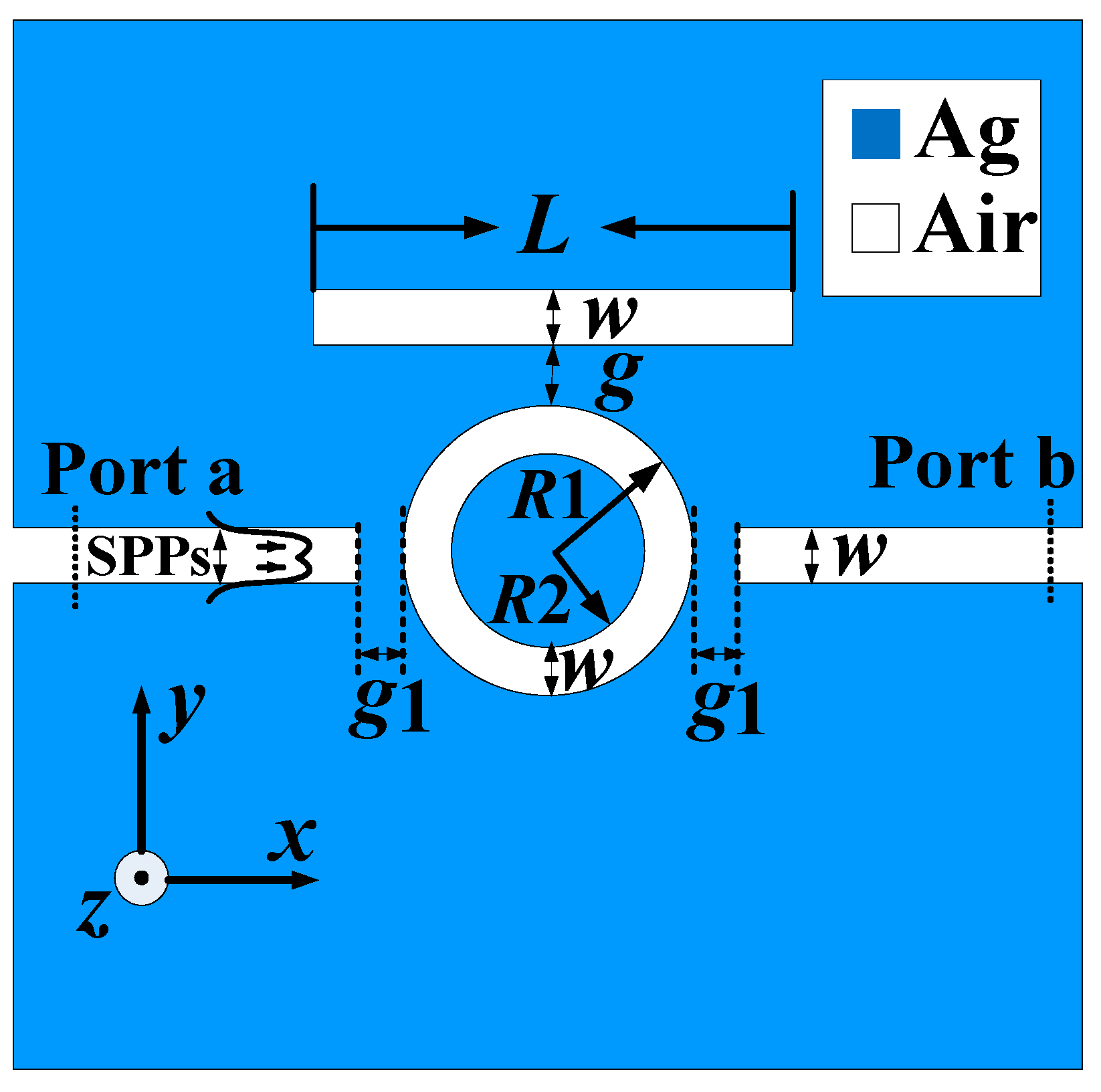
2. Materials and Methods

Figure 1 shows the proposed plasmonic MIM waveguide system for Fano resonance. The blue and white parts represent silver (εm = εAg) and air (εd = 1.0), respectively. The width of the MIM waveguide is w. The inner and outer radii of the ring cavity resonator are R1 and R2 respectively, with the difference between R1 and R2 fixed at w. The rectangle resonator has a side length of L and a width of w. The coupling distance between the rectangle resonator and the ring resonator is g. The gap between the bus waveguide and the ring resonator is g1.
The dielectric constant of Ag is described by the Drude model [20]:
ε m ( w ) = ε w p 2 w ( w + i γ )
where, ε is the infinite dielectric constant, and the angular frequency ωp and γ stand is the bulk plasma frequency standing for the natural frequency of the oscillations of free-conduction electrons and the electron collision frequency, respectively. ω is the angular frequency of incident light in a vacuum. These parameters for silver can be set as ε = 3.7, ωp = 1.38 × 10¹⁶ Hz and γ = 2.73 × 10¹³ Hz.
In the subwavelength MIM plasmonic waveguide, the SSPs propagates in a TM mode. The dispersion equation of the odd mode in the MIM plasmonic waveguide is as follows [2]:
ε d k m + ε m k d tanh ( k d w 2 ) = 0
where km and kd are k d 2 = ε d k 0 2 β 2 and k m 2 = ε m k 0 2 β 2 , with εd and εm defined as dielectric constants of the dielectric medium and the metal, respectively. k0 = 2π/λ0 is the wave vector in a vacuum. β represents the complex propagation constant of SPPs. w is the width of the waveguide. The effective refractive index of the plasmonic waveguide is expressed as Neff. The relationship between Neff and β is Neff = β/k0 = λ/λspps. The Neff can be obtained by solving Equations (1) and (2).
In a rectangular plasmonic cavity, the accumulated phase shift per round trip for the SPPs is Φ = 4πneffL1/λ + 2φ. neff is the real part of Neff. Constructive interference should occur when Φ = 2πN, thus the resonance wavelength of mode (0, N) is determined by [21]:
λ = 2 n eff L 1 N φ / π
The physics simulations (transmission spectrums and Hz field distributions) of the proposed structure were investigated by the FEM with COMSOL Multiphysics. The SSPs were excited in the input port a and finally collected in the output port b. The Fano resonance in our system originates from the interference effect between a localized state caused by the rectangle resonator and a continuum supported by the rectangle resonator. The Fano resonances were studied in the transmittance spectrum. The transmittance, T = |S21|2, is the transmission coefficient from port a to port b.

3. Results and Discussion

3.1. Analysis of the Formation Laws of the ‘Direction’ of the Fano Line-Shape

In the simulation, these geometric parameters are set as R1 = 195 nm, R2 = 145 nm, L = 480 nm, w = 50 nm, and g = 20 nm, g1 = 10 nm, respectively. To investigate the formation mechanism of Fano resonance, the transmission spectrums of a single ring MIM waveguide, a single rectangle MIM waveguide, and a Fano resonant plasmonic system are shown in Figure 2.
For the single ring MIM waveguide, the transmission spectrums are shown in the dotted blue line, with three transmission peaks of symmetric Lorentzian-like line-shape (providing continuum for the Fano resonator). The corresponding Hz field distributions of the three transmission resonance peaks are given; and the field modes are expressed as ring mode (m, 0) and defined by the number of the dark line in the upper half rings (the Hz field distributions of the upper and lower half ring are symmetric, and only the upper half ring interacts with the rectangle), which are ring modes (2, 0), (3, 0), (4, 0) from right to left, respectively. For the single rectangle MIM waveguide, the transmission spectrums are shown as a dotted red line, with three narrow transmission dips (supporting the located state for the Fano resonator). The corresponding Hz field modes of the three transmission resonance valleys are expressed as rectangle mode (n, 0) and defined by the number of the dark lines in the rectangle, which are rectangle modes (2, 0), (3, 0), (4, 0) from right to left, respectively. The black solid line is the result of the coupling between the continuum and the located state; and the three sharp asymmetric line-shapes in the black solid line are the results of Fano resonance, marked as FR1, FR2, and FR3. The corresponding Hz field distributions of the three Fano resonance peaks exhibit at λ = 376, 485, 713 nm. From these Hz field distributions, the FR1, FR2, and FR3 originate from the couple between the ring mode (4, 0) and rectangle mode (4, 0), the ring mode (3, 0), and rectangle mode (3, 0), and the ring mode (2, 0) and rectangle mode (2, 0), respectively.
In Figure 3, the nephogram (‘nephogram’ in this paper is not a real nephogram as in meteorology, but is only used to represent a figure of a series of transmission spectrums versus two variables) of Fano resonance phenomenon in the transmission spectrum is exhibited, when the rectangle cavity resonator L changes from 10–1000 nm with the step L is 10 nm and the wavelengths of incident natural light are in the visible and infrared wavelength range.
In the nephogram, the black dashed lines represent a series of transmission resonance peaks of different resonance modes in a single ring MIM waveguide. The corresponding resonance modes are ring modes (1,0), (2, 0), (3, 0), (4, 0) from right to left, respectively. The white dashed lines represent a series of transmission resonance peaks of resonance modes in the rectangle MIM waveguide. The corresponding resonance modes are rectangle modes (0,1), (0, 2), …, and (0, 5), …, respectively. The red-yellow parts are the transmission spectrums of the interaction between ring modes and ring modes. The split parts of the red-yellow parts (e.g., the parts in dotted red and dotted green boxes) are the results of Fano resonances between the modes in the ring resonator and the rectangle resonator.
Through the analysis, very evident laws are found. When orders m of rectangle modes in the rectangle resonator and n of the ring modes in ring resonator are both odd or both even, the two modes in the ring and rectangle resonators strongly couple with each other, and the corresponding transmission spectrum bands of the Fano resonances are completely split (e.g., the parts of the dotted red box). While, when the orders, m, n, respectively are odd and even (even and odd), the two modes in the ring and rectangle resonators weekly couple with each other and the corresponding transmission spectrum bands of the Fano resonances are incomplete splits (e.g., the part of the dotted green box). Even the Fano resonance coupled by the ring mode (2, 0) and rectangle mode (1, 0) is extremely weak; the corresponding incomplete transmission spectrum band does not get demonstrated.
For further analysis of the ‘direction’ line shapes of the Fano resonances for the complete and incomplete split transmission spectrum bands, the transmission spectrums in the dotted red and green boxes with different rectangle length L are shown in Figure 4a,b, respectively.
Meanwhile, to deeply understand the physics mechanism of these Fano resonances, Figure 5a–c give the Hz field distributions at the Fano resonance valleys of points ‘A’–‘E’ in Figure 4a,b, respectively.
Firstly, the formula for the line shape of the Fano resonance is analyzed, which is [7,8,22]:
σ = ( ε + q ) 2 ( ε 2 + 1 )
q is given by the ratio between the optical response of the located state and the continuum and describes the degree of asymmetry of the resonance. Reduced energy ε is defined by 2(EEF)/Γ, with EF being resonant energy and Γ width of the auto-ionized state. In the limit |q|→∞, the line-shape is entirely determined by the transition through the discrete state only with the standard ‘Lorentzian’ profile. The case of q = 0 is unique to the Fano resonance and describes a symmetrical dip, sometimes called an anti-resonance. In the case of q < 0, the ‘direction’ of asymmetric Fano line-shape is negative (e.g., the Fano line-shape in Figure 4a with L 460 or 480, where Fano resonance peak is on the left and Fano resonance valley is on the right). In the case of q > 0, the ‘direction’ of asymmetric Fano line-shape is positive (e.g., the Fano line-shape in Figure 4a with L 520 or 540 nm, where Fano resonance peak is on the left and Fano resonance valley is on the right).
In Figure 4a, there are two very weak dips (marked as Dip connected by the dotted green line) and a set of strong (marked as FR connected by the dotted red line) Fano resonances. The very weak dips only occur with L = 520 and 540 nm on the right side of the transmission summit of symmetric Lorentzian-like line-shape. The symmetric Lorentzian-like line-shape is dominated by the ring resonator and provides the continuum for the Fano resonance, the corresponding transmission summits connected by the dotted blue line in Figure 4a. The two very weak dips originate from the couple between the ring odd modes (3, 0) and very weak rectangle even modes (3, 0), which can be known from the Hz field distributions of points ‘A’ in Figure 5a with L = 540 nm. The strong Fano resonances couple by rectangle odd modes (3, 0) and ring odd modes (3, 0). The corresponding Hz field distributions of points ‘B’ and ‘C’ are shown in Figure 5a with L = 480 and 540 nm. It can be seen that the phases of the two rectangular modes (3, 0) are the same, while the two ring modes (3, 0) have some differences. With the increase of L, the Fano resonance shows a red shift and moves from the left side of the transmission summit of symmetric Lorentzian-like line-shape (with the ‘direction’ of the Fano line-shape q < 0) to the right side of the transmission summit (with the ‘direction’ of the Fano line-shape q > 0). In addition, it can be noted that the phase of the weak rectangle even mode (3, 0) of the dip is different from that of the Fano resonance valley in Figure 5a with L = 540 nm. In Figure 4b, these relatively weak Fano resonances couple by rectangle modes (2, 0) and ring modes (3, 0) can be seen. It is to be noted that no matter how big L is, when L is a certain value the rectangle mode (3, 0) simultaneously contributes two Fano resonances (connected by dotted red lines and respectively marked as LFR and RFR). These are respectively located on the left side (with the ‘direction’ of the Fano line-shape q > 0) and right side (with the ‘direction’ of the Fano line-shape q < 0) of the same transmission summit (connected by a dotted blue line) of symmetric Lorentzian-like line-shape. With the L increasing, the two kinds of Fano resonances either show a red shift (the two sets of Fano resonances are marked as LFR and RFR). The corresponding Hz field distributions of points ‘D’ and ‘E’ in Figure 4b are both shown in Figure 5b with L = 290 nm. It can be seen that the phases of the two ring modes (3, 0) are the same, while the two rectangular modes are both modes (3, 0) with a phase difference of π. The results are very interesting. According to Equation (3), in the fixed-size rectangle cavities, although the phase is different the same mode should have the same peak position. However, our results demonstrate in the same size rectangle cavities, when the rectangle cavity couples with the ring MIM waveguide shown in Figure 1, the phases of modes can influence the Fano peak positions. The conclusion is suitable for other couples between the ring odd and rectangle even (rectangle even and ring odd) modes, as shown in Figure 3. Unfortunately, the intensities of these Fano resonances in Figure 4b are obviously weaker than those in Figure 4a.
Combined with the analyses of Figure 3, Figure 4 and Figure 5, we can summarize and generalize the general law of formation of the ‘direction’ of the Fano line-shape. When the orders m of the mode (m, 0) in ring resonator and n of the mode (n, 0) in rectangle resonator are both odd or both even, and the Fano resonance occurs on the location of the increasing slope of the symmetric Lorentzian-like line-shape with wavelength increasing (the left side of the transmission summit of Lorentzian-like line-shape), the ‘direction’ of the Fano line-shape is negative, q < 0; while and the Fano resonance occurs on the location of decreasing slope of the symmetric Lorentzian-like line-shape with wavelength increasing (the right side of the transmission summit of Lorentzian-like line-shape), the ‘direction’ of Fano line-shape is positive, q > 0. For the condition of the shape parameter q = 0 (e.g., Figure 4a with L = 500 nm), the resonance frequencies of the ring and rectangle are equal. When the orders m of the mode (m, 0) in ring resonator and n of the mode (n, 0) in rectangle resonator are respectively odd and even (even and odd), and the Fano resonance occurs on the location of the increasing slope of the symmetric Lorentzian-like line-shape with the wavelength increasing (the left side of the transmission summit) and the ‘direction’ of the Fano line-shape positive, q > 0; while the Fano resonance occurs on the location of decreasing slope of the symmetric Lorentzian-like line-shape with wavelength increasing (the right side of the transmission summit) and the ‘direction’ of the Fano line-shape negative, q < 0.

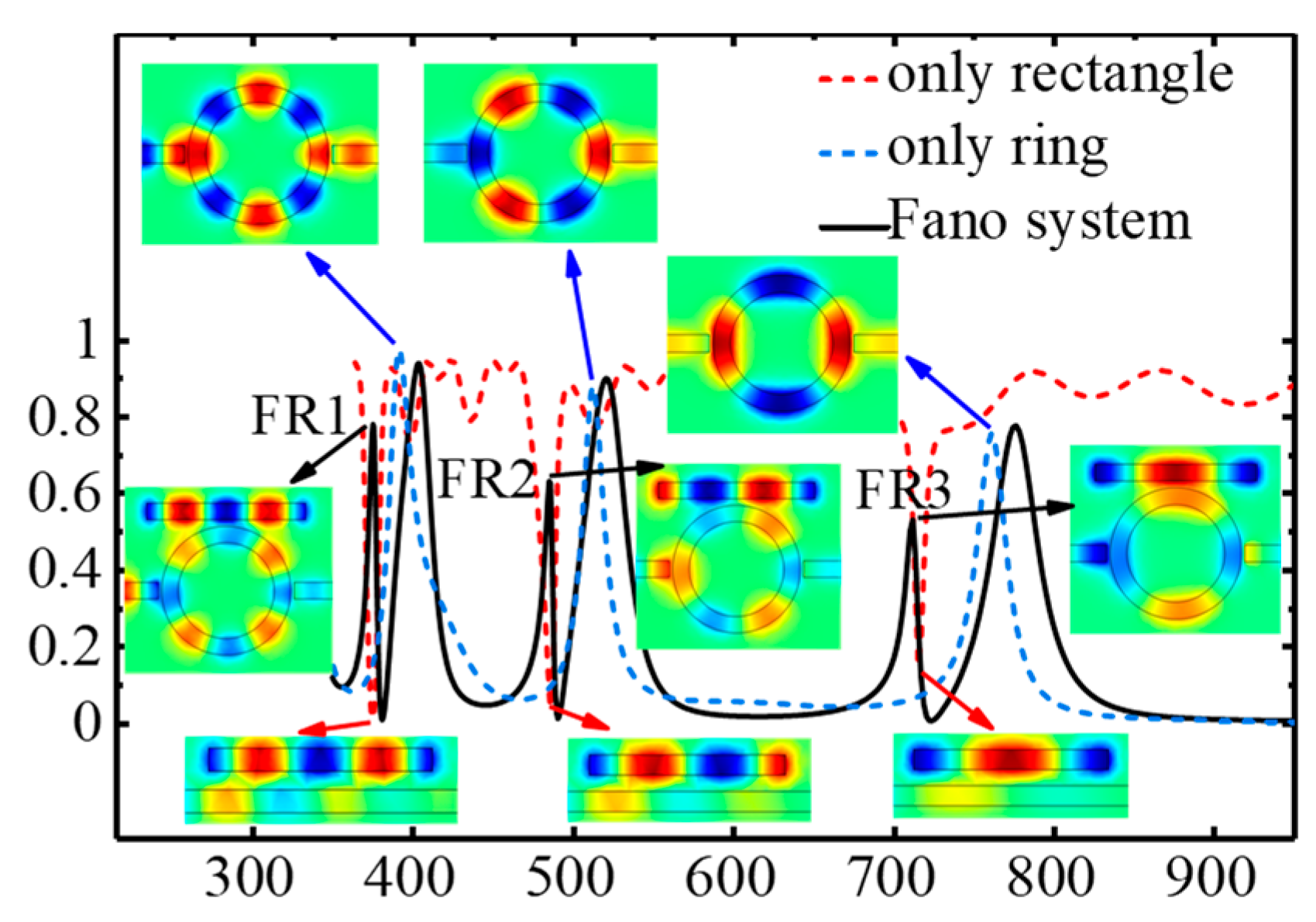
3.2. Analysis of Optimal Condition for the Generation of Multiple Fano Resonances

Figure 6a shows the nephogram of the transmission spectrum of the proposed Fano system with the wavelength varying from 400 to 1000 nm and the coupling distance g changing from 10 to 80 nm with the other parameters kept unchanged. Figure 6b shows the transmission spectrums from Figure 6a with g = 20, 30, and 40 nm, respectively.
As can be seen, when g is bigger (e.g., g = 70 nm), the coupling has not happened yet. As g decreases, the coupling of the two resonators becomes stronger, resulting in modes splitting, and the FR1, FR2, and FR3 (the three narrowly red-yellow spectral bands from left to right) emerge and become stronger. The smaller g is, the more obvious the extent of mode splitting is. With the g decreasing, the resonance wavelength of FR1, FR2, and FR3 is almost unchanged, while the Lorentzian-like line-shapes connected by the dotted blue lines in Figure 6b (the three broadly red-yellow spectral bands in Figure 6a) show an obvious blue shift. Furthermore, combined with the analyses in Figure 3, Figure 4 and Figure 5, the optimal condition for the generation of multiple Fano resonances is obtained. The optimal condition is that the effective length of the ring resonator is close to that of the rectangle resonator with a reasonable and smaller coupling distance g. At this condition, for the same modes (the orders m and n are the same) the resonance frequency of ring resonance is close to that of rectangle resonance, resulting in a stronger Fano resonance. Specifically, when L = 480 nm the effective length of ring resonance is close to that of a rectangle resonator with g = 20 nm in Figure 2 or Figure 4. Thus, for the modes that the orders m and n are the same (m = n = 2, 3, or 4) the resonance frequency of ring resonance is close to that of rectangle resonance, with three stronger Fano resonances. Compared to a single Fano resonance, a plasmonic spectrum line, which contains multiple Fano resonances, can be simultaneously adjusted at several multiple different spectral locations. And it would be applied to multiwavelength surface-enhanced Raman scattering (SERS), and biosensing [23].

3.3. Nano-Sensing Analysis

In Figure 7a, the impact of refractive index n in the rectangle resonator is also studied with the optimal condition for the generation of multiple Fano resonances (the geometric parameters are consistent with those in Figure 2). As n increases from 1 to 1.02, the wavelength responses can be adjusted from 375.5 nm to 380.2 nm for FR1, from 485.4 nm to 493.4 nm for FR2, and from 712.6 nm to 722.9 nm for FR3, demonstrating a significant sensitivity to the change of environmental refractive index. To better evaluate the performance of refractive index sensing of the Fano resonance, the dimensionless figure of merit (FOM) is studied. The FOM at the frequency λ can be represented as [18]:
FOM = Δ T T Δ n = T ( λ , n ) T ( λ , n 0 ) T ( λ , n 0 ) Δ n
where T(λ, n0) is the original value of transmission, and T(λ, n0) is the transmission after changing the environmental refractive index. ∆n = nn0, n0 is the environmental refractive index in the original state, and n is the environmental refractive index after changing.
Figure 7b shows the computed FOMs with n 1.01, 1.02, and 1.03, where the max FOM can reach 9591 at 750 nm with n = 1.02, which is greater than the max FOM = 3200, 5500, and 6838 found in [6,24,25], respectively.

4. Conclusions

We investigate and find the influencing factors and formation laws of the direction of the Fano line-shape, and the optimal condition for the generation of multiple Fano resonances in a Fano system consisting of a ring MIM waveguide coupled with a rectangle resonator. The rule is as follows. When the orders m of the mode (m, 0) in ring resonator and n of the mode (n, 0) in rectangle resonator are both odd or both even, whether the Fano resonance occurs on the left or right of the transmission summit of a symmetric Lorentzian-like line-shape dominated by ring resonator and providing continuum for Fano resonance, the Fano resonance peak is farther from the transmission summit of the Lorentzian-like line-shape than the Fano resonance valley. When the orders m of the mode (m, 0) in the ring resonator and n of the mode (n, 0) in the rectangle resonator are odd and even, respectively (even and odd respectively), whether the Fano resonance occurs on the left or right of the transmission summit of a symmetric Lorentzian-like line-shape dominated by ring resonator and providing continuum for Fano resonance, the Fano resonance valley is farther from transmission summit of the Lorentzian-like line-shape than the Fano resonance peak. The optimal condition for the generation of multiple Fano resonances is that the effective length of the ring resonator is close to that of the rectangle resonator with a reasonable and smaller coupling distance g. The conclusions can provide a theoretical foundation for the formation laws of the directional of the line shape of Fano resonance and the generation of multiple Fano resonances in the designs of plasmonic nanodevices. Furthermore, because the Fano resonance peaks of the proposed system are very sensitive to the environmental refractive index, when the plasmonic MIM guide and the ring and rectangle resonators are filled by high refractive index material like the study in the paper [26], the Fano resonance phenomenon and the nano-sensing of the environmental refractive index can be extended to the mid-infrared wavelength range.

Author Contributions

Conceptualization and methodology, Z.S., D.Z. and L.C.; software, D.Z. and L.C.; writing—original draft preparation, Z.S., D.Z. and L.C.; writing—review and editing, Z.S. and D.Z. All authors have read and agreed to the published version of the manuscript.

Funding

This research received no external funding.

Data Availability Statement

The data in this study are available from the corresponding authors upon request.

Conflicts of Interest

The authors declare no conflict of interest.

References

  1. Barnes, W.L.; Dereux, A.; Ebbesen, T.W. Surface plasmon subwavelength optics. Nature 2003, 424, 824–830. [Google Scholar] [CrossRef]
  2. Maier, S.A. Plasmonics: Fundamentals and Applications. In Plasmonics: Fundamentals and Applications; Springer Science & Business Media: Cham, Switzerland, 2007; pp. 1–9. [Google Scholar]
  3. Ebbesen, T.W.; Lezec, H.J.; Ghaemi, H.F.; Thio, T.; Wolff, P.A. Extraordinary optical transmission through sub-wavelength hole arrays. Nature 1998, 391, 1114–1117. [Google Scholar] [CrossRef]
  4. Ebbesen, T.W.; Genet, C.; Bozhevolnyi, S.I. Surface-plasmon circuitry. Phys. Today 2008, 61, 44–50. [Google Scholar] [CrossRef] [Green Version]
  5. Mizaikoff, B. Waveguide-enhanced mid-infrared chem/bio sensors. Chem. Soc. Rev. 2013, 42, 8683–8699. [Google Scholar] [CrossRef] [PubMed]
  6. Chen, Z.; Yu, L.; Wang, L.; Duan, G.; Zhao, Y.; Xiao, J. Sharp Asymmetric Line Shapes in a Plasmonic Waveguide System and its Application in Nanosensor. J. Lightwave Technol. 2015, 33, 3250–3253. [Google Scholar] [CrossRef]
  7. Miroshnichenko, A.E.; Flach, S.; Kivshar, Y.S. Fano resonances in nanoscale structures. Rev. Mod. Phys. 2010, 82, 2257–2298. [Google Scholar] [CrossRef] [Green Version]
  8. Fano, U. Effects of Configuration Interaction on Intensities and Phase Shifts. Phys. Rev. 1961, 124, 1866–1878. [Google Scholar] [CrossRef]
  9. Wen, K.; Hu, Y.; Chen, L.; Zhou, J.; Lei, L.; Guo, Z. Fano Resonance with Ultra-High Figure of Merits Based on Plasmonic Metal-Insulator-Metal Waveguide. Plasmonics 2015, 10, 27–32. [Google Scholar] [CrossRef]
  10. Yun, B.F.; Zhang, R.H.; Hu, G.H.; Cui, Y.P. Ultra Sharp Fano Resonances Induced by Coupling between Plasmonic Stub and Circular Cavity Resonators. Plasmonics 2016, 11, 1157–1162. [Google Scholar]
  11. Zhang, Z.D.; Wang, R.B.; Zhang, Z.Y.; Tang, J.; Zhang, W.D.; Xue, C.Y.; Yan, S.B. Electromagnetically Induced Transparency and Refractive Index Sensing for a Plasmonic Waveguide with a Stub Coupled Ring Resonator. Plasmonics 2017, 12, 1007–1013. [Google Scholar] [CrossRef]
  12. Chen, Z.; Yu, Y.; Wang, Y.; Guo, N.; Xiao, L. Compact Plasmonic Structure Induced Mode Excitation and Fano Resonance. Plasmonics 2020, 15, 2177–2183. [Google Scholar] [CrossRef]
  13. Yang, X.; Hua, E.; Su, H.; Guo, J.; Yan, S. A Nanostructure with Defect Based on Fano Resonance for Application on Refractive-Index and Temperature Sensing. Sensors 2020, 20, 4125. [Google Scholar] [CrossRef]
  14. Su, C.; Zhu, J. Novel SPR Sensor Based on MIM-based Waveguide and an Asymmetric Cross-shaped Resonator. Plasmonics 2021, 16, 769–775. [Google Scholar] [CrossRef]
  15. Chen, Y.; Luo, P.; Liu, X.; Di, Y.; Han, S.; Cui, X.; He, L. Sensing performance analysis on Fano resonance of metallic double-baffle contained MDM waveguide coupled ring resonator. Opt. Laser Technol. 2018, 101, 273–278. [Google Scholar] [CrossRef]
  16. Shahamat, Y.; Vahedi, M. Mid-infrared plasmonically induced absorption and transparency in a Si-based structure for temperature sensing and switching applications. Opt. Commun. 2019, 430, 227–233. [Google Scholar] [CrossRef]
  17. Zhu, J.; Li, N. MIM waveguide structure consisting of a semicircular resonant cavity coupled with a key-shaped resonant cavity. Opt. Express 2020, 28, 19978–19987. [Google Scholar] [CrossRef] [PubMed]
  18. Becker, J.; Trügler, A.; Jakab, A.; Hohenester, U.; Sönnichsen, C. The Optimal Aspect Ratio of Gold Nanorods for Plasmonic Bio-sensing. Plasmonics 2010, 5, 161–167. [Google Scholar] [CrossRef]
  19. Wang, Y.L.; Li, S.L.; Zhang, Y.Y.; Yu, L. Ultrasharp Fano Resonances Based on the Circular Cavity Optimized by a Metallic Nanodisk. IEEE Photonics J. 2016, 8, 8. [Google Scholar] [CrossRef] [Green Version]
  20. Lin, X.-S.; Huang, X.-G. Tooth-shaped plasmonic waveguide filters with nanometeric sizes. Opt. Lett. 2008, 33, 2874–2876. [Google Scholar] [CrossRef] [PubMed]
  21. Chen, J.; Sun, C.; Gong, Q. Fano resonances in a single defect nanocavity coupled with a plasmonic waveguide. Opt. Lett. 2014, 39, 52–55. [Google Scholar] [CrossRef]
  22. Gallinet, B.; Martin, O.J.F. Influence of Electromagnetic Interactions on the Line Shape of Plasmonic Fano Resonances. ACS Nano 2011, 5, 8999–9008. [Google Scholar] [CrossRef] [PubMed] [Green Version]
  23. Liu, N.; Mukherjee, S.; Bao, K.; Li, Y.; Brown, L.V.; Nordlander, P.; Halas, N.J. Manipulating Magnetic Plasmon Propagation in Metallic Nanocluster Networks. ACS Nano 2012, 6, 5482–5488. [Google Scholar] [CrossRef] [PubMed]
  24. Yi, X.C.; Tian, J.P.; Yang, R.C. Tunable Fano resonance in MDM stub waveguide coupled with a U-shaped cavity. Eur. Phys. J. D 2018, 72, 9. [Google Scholar] [CrossRef]
  25. Liu, D.D.; Wang, J.C.; Zhang, F.; Pan, Y.W.; Lu, J.; Ni, X.W. Tunable Plasmonic Band-Pass Filter with Dual Side-Coupled Circular Ring Resonators. Sensors 2017, 17, 585. [Google Scholar] [CrossRef] [Green Version]
  26. Esteban, O.; Gonzalez-Cano, A.; Mizaikoff, B.; Diaz-Herrera, N.; Navarrete, M.C. Generation of Surface Plasmons at Waveguide Surfaces in the Mid-Infrared Region. Plasmonics 2012, 7, 647–652. [Google Scholar] [CrossRef]
Figure 1. Schematic of the metal-insulator-metal (MIM) plasmonic waveguide system for Fano resonance.
Crystals 11 00819 g001
Figure 2. The transmission spectrums of the Fano system with the corresponding Hz field distributions of Fano resonance peaks, of a single ring metal-insulator-metal (MIM) waveguide structure with the corresponding Hz field distributions of transmittance peaks, and of a single rectangle MIM waveguide structure with the corresponding Hz field distributions of transmittance valleys.
Crystals 11 00819 g002
Figure 3. Nephogram of Fano resonance transmission spectrums coupled by metal-insulator-metal (MIM) ring resonator and rectangle resonator with the rectangle resonator L varying from 0 to 1000 nm.
Crystals 11 00819 g003
Figure 4. Transmission spectrums for different values of rectangle resonator length L: (a) L = 460, 480, 500, 520, and 540 nm, (b) L = 270, 290, 310, 330, and 350 nm.
Crystals 11 00819 g004
Figure 5. Hz Field distributions of the four points: ‘A’, ‘B’, and ‘C’ (Fano peak) in Figure 3a, ‘D’ and ‘E’, (Fano valley) in Figure 3b. (a) L = 540 nm, λ = 529 nm, (b) L = 480 nm, λ = 514 nm (c) L = 540 nm, λ = 562 nm, (d) L = 290 nm, λ = 490 nm, and (e) L = 290 nm, λ = 536 nm.
Crystals 11 00819 g005
Figure 6. (a) Nephogram of transmission spectrums of the proposed Fano system as a function of g and wavelength with other parameters keep unchanged. (b) Transmission spectrums from Figure 5a with g = 10, 20, and 40 nm, respectively.
Crystals 11 00819 g006
Figure 7. (a) Transmission spectrums with n from 1 to 1.03. (b) Figure of merit (FOM) of FR1, FR2, and FR3 with different n.
Crystals 11 00819 g007
Publisher’s Note: MDPI stays neutral with regard to jurisdictional claims in published maps and institutional affiliations.

