Abstract
Commercial LiMn2O4 powder was used as the base material for probing magnesiation, cycling behavior, and structural stability/changes in (MgxLi1-x)Mn2O4 spinel cathodes in aqueous Mg(NO3)2 and non-aqueous Mg(TFSI)2/diglyme and Mg(Mg(HFIP)2 − 2Al(HFIP)3/diglyme electrolytes. Each of the samples was delithiated and, then, magnesiated electrochemically in the corresponding electrolyte. The electrochemical activity of the cathode cycled in aqueous electrolyte showed high reversibility during the oxidation process; however, large polarization and a relatively fast capacity fading were the culprits of the system. Cycling in Mg(TFSI)2/diglyme electrolyte solution resulted in much lower initial specific capacity compared to an aqueous counterpart, as well as a much faster failure. On the other hand, cycling in Mg(HFIP)2 − 2Al(HFIP)3/diglyme electrolyte solution demonstrated excellent cycling performance with very low polarization in the first cycles. The observed voltages for this system were near theoretical values for the Mg insertion. Although the electrochemical measurements suggest reversible magnesiation, detailed structural and analytical STEM investigation revealed the differences in the atomic structure and Mn valence of all three cathode samples upon cycling. The electrolytes’ influence on the structural rearrangement during Mg insertion is discussed for each of the three systems.
1. Introduction
The development of rechargeable magnesium batteries has gained a lot of interest in recent years, mainly due to the advantageous use of magnesium metal anode. Its high volumetric capacity (3833 mAh cm−3), possible non-dendritic deposition [1], natural abundance, and geographical distribution make it one of the most promising alternatives to current lithium-ion batteries. The first Mg-battery prototype was proposed by Aurbach et al. [2], and since then, many improvements have been made on all aspects of the battery system, including anode, cathode, and electrolyte [3,4]. The discovery and development of non-nucleophilic electrolytes opened a promising field of magnesium batteries combined with organic or sulfur-based cathodes [5,6]. Even though redox-active polymers or sulfur/carbon composites offer attractive energy storage systems, their low volumetric energy density neutralizes one of the most important advantages of the magnesium metal anode, namely, its high volumetric energy density. The use of inorganic materials with high gravimetric density would be beneficial to improve overall volumetric energy density, but reversible magnesium insertion into inorganic phases is limited to only a few known examples, mainly to sulfide-based materials [2,7,8]. Major challenges with magnesium insertion into inorganic materials are several: (i) desolvation of Mg2+ cation, (ii) structural stability, and (iii) low magnesium ion mobility within the structure in many of the proposed materials [9]. Chevrel phases, presented in the initial research, offer excellent reversibility and unusually high ion mobility [10] but their low capacity and low voltage limit their potential use.
The work on layered TiS2 and spinel-type Ti2S4 reported by Nazar’s group, employed the use of sulfides to lessen the interactions between the host and Mg2+ ion [7,8]. At 60 °C and C/20 rate, they achieved approximately 160 mAh g−1 for both materials. However, at 20 °C, Tao et al. fabricated TiS2 nanotubes and achieved higher initial capacities but observed severe capacity fade. Use of selenides such as TiSe2 and WSe2 improved stability at the cost of lower theoretical specific capacity [11,12]. Although chalcogenide-based materials show promising electrochemical behavior, their theoretical energy density remains relatively low for wide commercial acceptance. Thus, the development of high-capacity and high-voltage magnesium cathodes is still a major obstacle toward practical magnesium batteries with high volumetric energy density.
Several different transition metal oxides have been proposed as potential high voltage cathode materials for magnesium batteries [13]. Among them, manganese oxides are particularly interesting due to their high potential and theoretical capacity (616.6 mAh g−1 based on MnO2 molecular weight and considering two-electron reaction), structural variety, and ability to accommodate highly polarizable Mg cations. Theoretical work published by Ling et al. [14] suggests a possible magnesium insertion into the various manganese oxide polymorphs. Ling and coworkers predicted that the spinel phase and (Mg)Mn2O4 isostructural to (Ca)Fe2O4 are potential candidates for reversible magnesium intercalation.
Apart from the theoretical work, several groups have used different manganese oxides as insertion host structures for magnesium cations. Sinha et al. [15] showed electrochemical magnesium insertion in LiMn2O4 in aqueous media using cyclic voltammetry measurements. In this work, the anodic and cathodic peaks corresponding to the removal of Li+ ions during the first cycle and subsequent insertion/disinsertion of Mg2+ ions are clearly visible. Yuan et al. [16] investigated intercalation of polyvalent anions in λ-MnO2, prepared by simple acid treatment of LiMn2O4. Magnesium insertion was performed from 0.5 M MgCl2 aqueous solutions and resulted in a high capacity (545 mAh g−1) at a current density of 13.6 mA g− [1]. The formation of MgMn2O4 was proposed from characterization of the sample with inserted magnesium using XPS and powder X-ray diffraction spectroscopy.
A more detailed mechanism study of magnesium intercalation into acid-leached spinel MnO2 host was performed by Kim and coworkers [17]. X-ray diffraction characterization pointed out the formation of λ-MnO2 during charge and formation of tetragonally distorted spinel lattice during discharge. The structure was visualized with ABF STEM, and the Mn reduction was confirmed with XAS measurements. Additional evidence of magnesium insertion into the structure was obtained by 25Mg NMR, where Mg2+ was found to be in close proximity to paramagnetic centers (Mn4+ and Mn3+) in the structure. The formation of Mg2+ indicates structural changes that were observed [11,18] as the formation of a rock salt (Mn3O4) phase at the surface.
Despite several studies, a detailed electrochemical and structural comparison of possible magnesium insertion from electrolytes with a different coordination of magnesium is missing. In this work, we discuss magnesium insertion into delithiated manganese spinel in three different electrolytes that possess different solvation properties for magnesium. Magnesium insertion and its reversibility have been studied using different electrochemical techniques. The differences in the capacity fading were thoroughly evaluated with TEM using EDX and EELS. The differences between electrolytes and the associated crystallographic changes are discussed.
2. Materials and Methods
2.1. Electrochemical Measurements
Cyclic voltammetry measurements were performed on PARstat potentiostat in a beaker cell with 0.1 M aqueous solution of Mg(NO3)2. Cathode film on glassy carbon electrode was prepared by suspending a mixture of LiMn2O4 and Printex XE2 carbon with mass ratio 1:1 in ultra-pure deionized water, followed by adding 1 wt.% of polytetrafluoroethylene (PTFE) per solid mass. Final concentration of LiMn2O4 in suspension was 0.5 mg mL−1. Forty microliters of suspension (active mass of 20 μg) were dropped on the glassy carbon surface and left to dry at 50 °C. Graphite rod was used as a counter electrode and Ag/AgCl (3 M KCl) electrode as a reference. Cyclic voltammetry measurements were performed in the window from −0.5 to 1 V vs. Ag/AgCl with a scan rate of 5 mV s−1.
Galvanostatic measurements in aqueous electrolyte were performed on BioLogic VMP3 potentiostat/galvanostat. Setup was the same as in cyclic voltammetry measurements, except electrolyte, which was more concentrated (1 M aqueous solution of Mg(NO3)2). The experiment was performed with C/4 (135 mA g−1) current density.
For measurements in non-aqueous electrolytes the self-standing electrodes were prepared by mixing the active material, Printex XE2 carbon as conductive additive, and the polymer binder polytetrafluoroethylene (PTFE) in a mass ratio of 60:30:10 in 2-propanol. Used electrolytes include 0.45 M magnesium bis(trifluoromethanesulfonimide) (Mg(TFSI)2–99.5%, Solvionic) in diglyme and 0.25 M Mg(HFIP)2-2Al(HFIP)3 in diglyme. HFIP salts were prepared by using the adapted procedure, reported by Herb et al. [19]. To a cooled mixture of hexafluoroisopropanol (HFIP-99% Apollo Scientific, dried over molecular sieves) and DME (99 %, Honeywell), AlMe3 (Sigma Aldrich, St. Louis, MO, USA) was added dropwise. After 15 min of stirring, the mixture was transferred to glovebox and stirred overnight. Mg(HFIP)2 was prepared from Bu2Mg (Sigma Aldrich) and dissolved in THF and HFIP, which was added dropwise over course of a few minutes. After exothermic reaction, the mixture was stirred overnight. In both cases, excess solvent was removed through decreased pressure evaporation. As-prepared salts were used for the preparation of 0.25 M Mg(HFIP)2-2Al(HFIP)3 in diglyme electrolyte. Brushed Mg foil (Gallium Source, 99.95%) was used as anode and was separated from the cathode with glass fiber separator (Whatman GF/A). The batteries were assembled in Swagelok cells and cycled with C/40 (13.5 mA g−1) or C/100 (5.4 mA g−1), respectively.
2.2. TEM Measurements
JEM-ARM200CF transmission electron microscope (JEOL, Tokyo, Japan) equipped with cold field-emission gun, Centurio energy dispersive X-ray spectrometer (EDX), Gatan GIFQuantum (Gatan, Plesanton, CA, USA), scanning TEM (STEM) unit, and various STEM detectors including annular bright field detector (STEM-ABF) was used for imaging structure of the samples down to atomic level, chemical composition mapping, and Mn valence monitoring. The microscope was operated at 80 keV in order to reduce sample damage [20].
2.3. ICP–OES Measurements
Elemental optical emission spectrometer 715-ES with ICP excitation (Varian, Palo Alto, CA, USA) was used to perform determination of Li, Mg, and Mn contents in cathode material upon magnesiation. Cycled cathodes were rinsed, dispersed in ethanol, and centrifuged. The last two steps were repeated three times to avoid electrolyte residue.
3. Results
Commercial LiMn2O4 was taken as a starting material without any pretreatment in order to keep the initial cubic spinel structure consistent. Electrochemical delithiation using cycling voltammetry (Figure 1) in 0.1 M water solution of Mg(NO3)2 shows typical Li anodic double peaks in the first cycle [15] at a potential ~0.7 V and ~0.9 V vs. Ag/AgCl reference electrode (~3.3 V and ~3.5 V vs. magnesium metal). In the subsequent reduction process, a low signature of Li insertion is clearly seen. In the second anodic polarization, this Li feature is absent. The estimated concentration of Li+ cations in electrolyte is in the range 5.5 × 10⁻⁶ M, which is several orders of magnitude lower compared to pristine Mg electrolyte solution. Upon further cycling, only peaks at 0.25 V and −0.01 V vs. Ag/AgCl reference electrode are present, which indicates potential rearrangements in the structure (Figure 1a). During the first cycles, anodic and cathodic peaks in the cycling voltammogram (Figure 1a) are increasing and stabilize around 20th cycle.
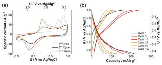
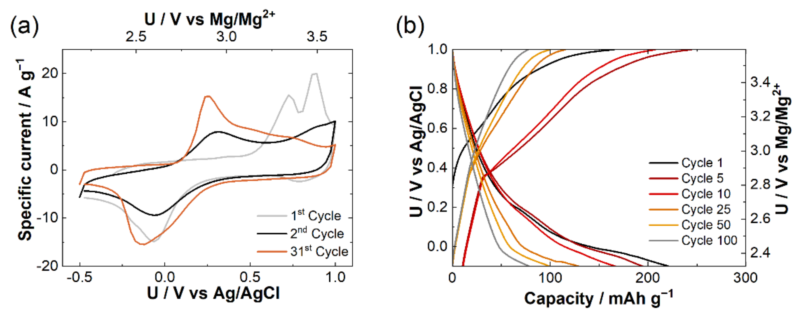
Figure 1.
(a) Cyclic voltammograms of LiMn2O4 in 0.1 M aqueous solution of Mg(NO3)2 and (b) galvanostatic cycling at C/4 rate in 1 M aqueous solution of Mg(NO3)2.
The galvanostatic cycling in 1 M Mg(NO3)2 in a water solution (Figure 1b) shows high electrochemical activity of the initial LiMn2O4. The first oxidation proceeds at a higher voltage compared to the following oxidation processes. This can be correlated to the electrochemical removal of Li from the LiMn2O4 structure. While capacity during the oxidation process in the first cycle corresponds to almost complete Li removal (obtained capacity is close to theoretical), the following reduction process exhibits an excess of capacity. Higher capacity during discharge in the first cycle is primarily due to the formation of a double-layer capacitance at the high-surface-area carbon black used in this study and partially due to degradation processes. The electrochemical activity observed during the oxidation process is almost fully reversible; however, the system exhibits large polarization and a relatively fast capacity fading.
Insertion of Mg from water-based electrolyte clearly shows that Mg can be inserted into the spinel structure from electrolytes where the Mg solvation is weak [21,22]. Since Mg metal cannot be used in water-based electrolytes, the use of non-aqueous electrolytes was evaluated. Mg insertion into manganese spinel from electrolytes containing chlorides (mixture of Mg(TFSI)2 and MgCl2 in TEGDME:DOL) was not possible. Galvanostatic cycling in electrolyte without chloride that contained only Mg(TFSI)2 dissolved in diglyme resulted in much lower initial specific capacity compared to an aqueous counterpart (Figure 2). Capacity in the first cycle was 65 mAh g−1, a slightly lower value, as it was obtained in the dual electrolyte system [23]. Here, the well-defined plateau of Mg insertion at approximately 2.5 V vs. Mg/Mg2+ counter electrode in the first cycle is in agreement with the cyclic voltammetry measurements in water-based solution. However, in the second cycle, only a small part of Mg can be removed at a potential value between 3.2 and 3.3 V vs. Mg counter electrode. Following insertion proceeds at an approximately 150 mV lower potential compared to that of the first cycle. Increasing polarization indicates a problem with the passivation of the magnesium metal, which was used as a negative electrode. Capacity fading during the initial cycles is very fast. It can be correlated either with the increase in the polarization during initial cycles or with the structural rearrangements in the spinel structure.
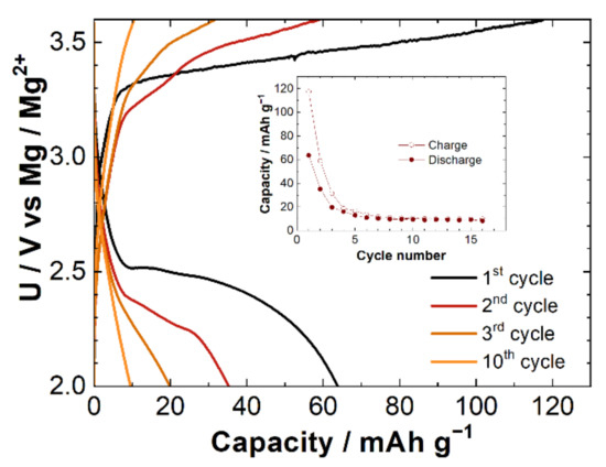
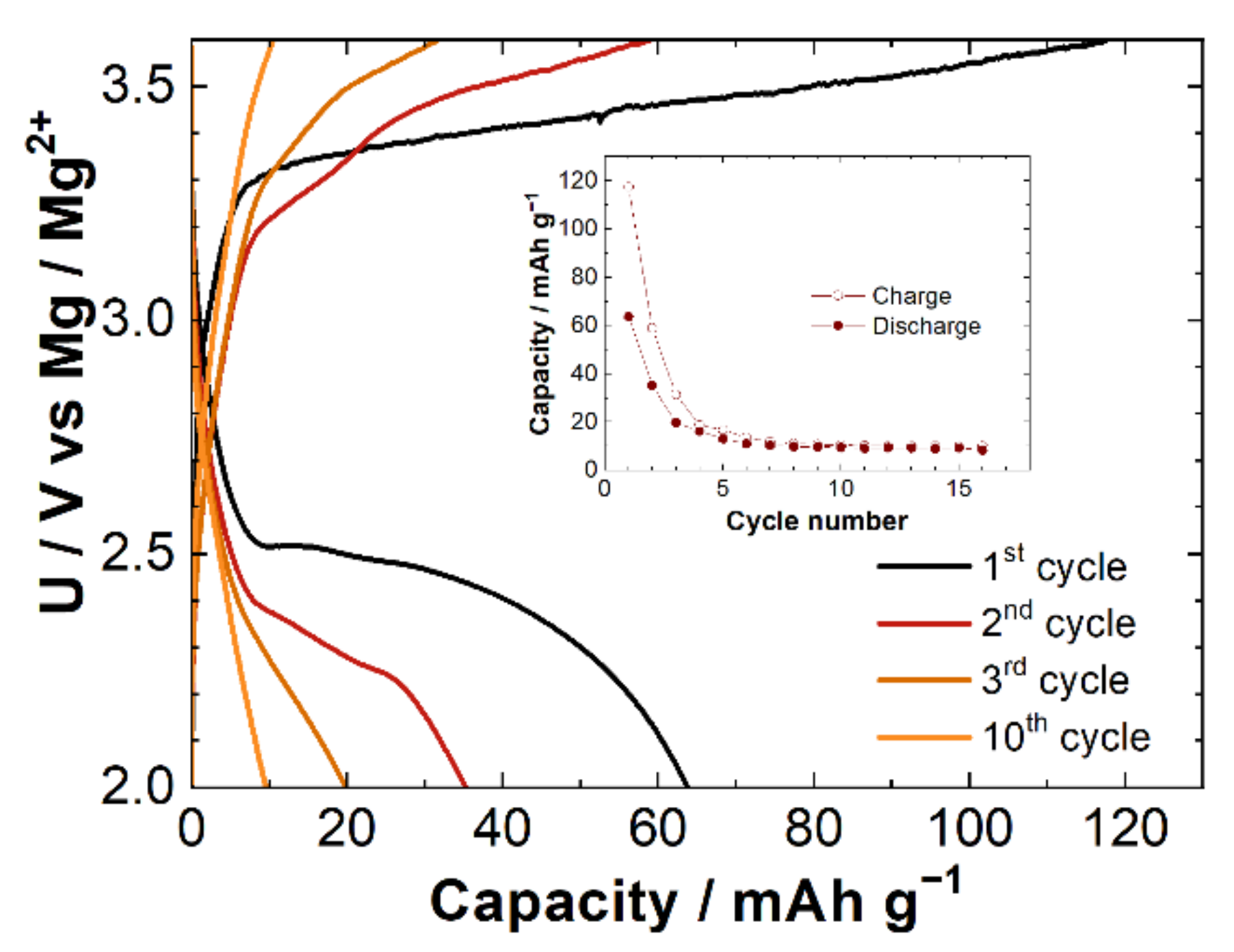
Figure 2.
Galvanostatic cycling in 0.6 M Mg(TFSI)2/diglyme electrolyte at C/20.
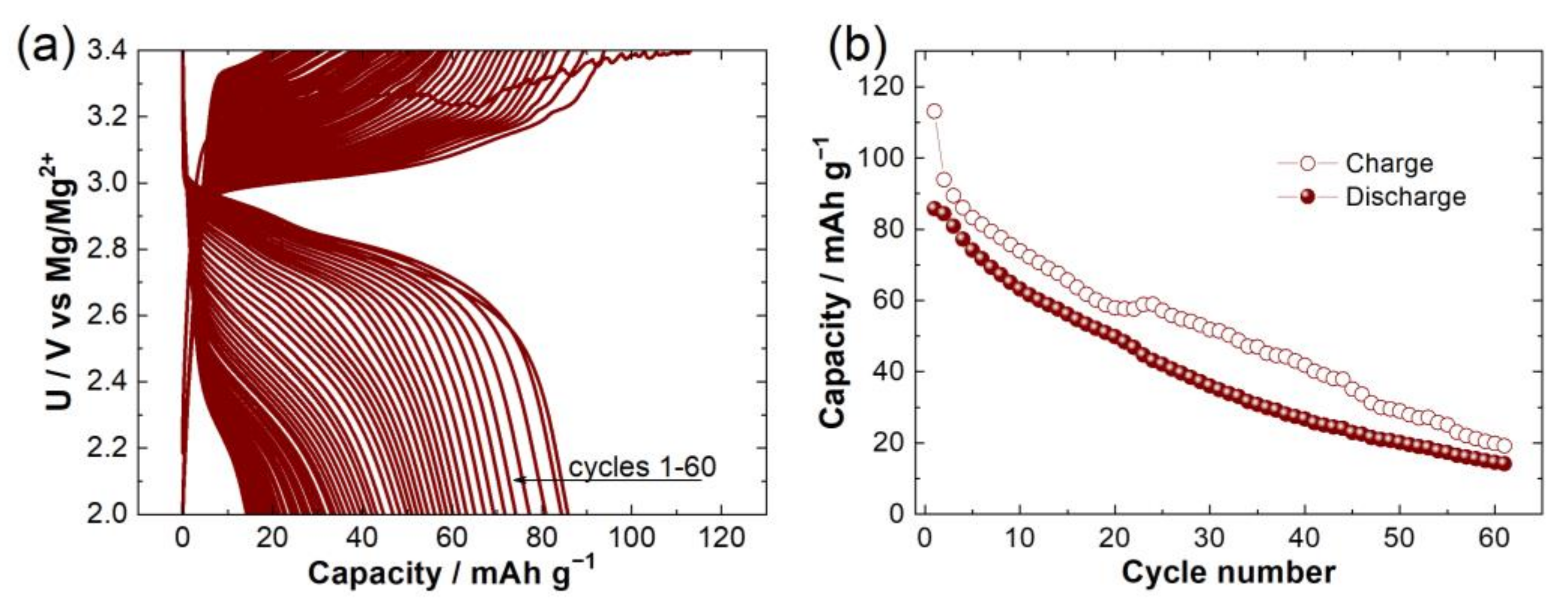
Demonstrated galvanostatic cycling in Mg(TFSI)2/diglyme electrolyte suggests possible partially reversible Mg insertion from the non-aqueous electrolyte. Nevertheless, the insertion is not possible in chloride-containing electrolyte due to the formation of MgCl+. Recent reports on use of bulky weakly coordinating salts, such as fluorinated alkoxyaluminates, indicated their benefits for the Mg-ion battery system, providing high conductivity and high efficiency of Mg plating [24]. The chosen electrolyte was shown to be also suitable in a combination with the manganese oxides [19]. Due to the nature of the anion, the Mg2+ desolvation is easier, making it less likely for solvated ion to try to be inserted into the structure. Galvanostatic cycling in 0.25 M Mg(HFIP)2-2Al(HFIP)3/diglyme electrolyte (Figure 3a,b) showed excellent cycling performance with a very low polarization in the formation cycles. The observed voltages are near theoretical values for the Mg insertion. Over time, the polarization gradually increases, but the increase is significantly slower than that observed in Mg(TFSI)2/diglyme electrolyte.

Figure 3.
(a) Galvanostatic cycling in 0.25 M Mg(HFIP)2-2Al(HFIP)3 in diglyme electrolyte at C/20. (b) Charge and discharge capacities through cycles.
In part, it can be explained with the structure of the HFIP electrolyte, which utilizes bulky weakly coordinating anion [25]. As a result, the desolvation of Mg2+ ions is easier, making it less likely for solvated ion to intercalate into the structure. One may speculate that the softer character of anion lessens its interactions with the surface of the particle and may influence the rate of degradation, as was confirmed with Li-ion batteries [26,27,28]. Unfortunately, there is no available research, yet, to elucidate these phenomena in Mg batteries, except a few brief notes, as in the paper on birnessite by Sun et al. With an XPS analysis, they found strongly bonded TFSI- anions on the surface of the cathode, concluding that the limiting factor for Mg intercalation is also the disruption of the ion pairing of the electrolyte salt in addition to the formation of thermodynamically favorable oxides [29].
One of the concerns that come with the use of non-aqueous electrolytes in the laboratory cells is related to the Li concentration in an electrolyte after its removal from the LiMn2O4 structure. Here, the amount of used electrolyte is much lower compared to that in a beaker cell. Due to a lower amount of the electrolyte, Li concentrations can reach up to 0.28 M, assuming a complete delithiation of the initial LiMn2O4 material. Hence, a better electrochemistry can be attributed to the supporting role of present Li ions. To rule this assumption out, ICP-OES measurements on the fully magnesiated samples were performed. In both non-aqueous electrolytes, the Li content was smaller than Mg, although the amounts were not negligible (Table 1).

Table 1.
Ratio between Mn, Mg, and Li after 5th charge in two non-aqueous electrolytes. Mole ratio of Mg and Li was normalized on Mn.
ICP results are consistent with electrochemistry in both non-aqueous electrolytes. Electrochemical extraction in Mg(TFSI)2/diglyme electrolyte showed relatively good electrochemical extraction of Li with limited insertion of Mg. The results obtained for 0.25 M Mg(HFIP)2-2Al(HFIP)3/diglyme electrolyte corroborate with the electrochemistry, since approximately 56 at.% of Li sites were substituted by Mg. This corresponds to approximately 83 mAh.g−1 capacity, which was observed in the formation cycles.
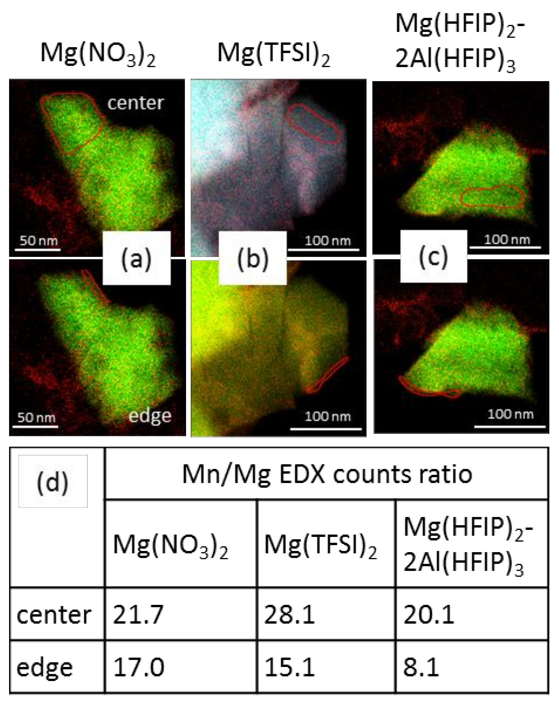
The Mg insertion and distribution in manganese spinel particles was assessed by STEM-EDX (Figure 4). Analysis of the sample cycled in the Mg(NO3)2 electrolyte (Figure 4a) confirmed that the anodic peak observed in the cyclic voltammogram (Figure 1a) corresponds to the magnesiation process. Although the Mg STEM-EDX maps (Figure S1) from all three samples seem to have a uniform contrast throughout the investigated particles, a closer look at Mn/Mg count ratios taken at the edge and in the interior areas of the particles reveals a different situation (Figure 4a–c, areas marked by the red lines). In all samples, the outer edges of the particles demonstrate a lower Mn/Mg count ratio (Figure 4d), which corresponds to a higher amount of Mg. This indicates a presence of core-shell structure with the magnesiated spinel oxide in the shell, and most likely, the remaining LiMn2O4 in the core is present. Both samples cycled in non-aqueous electrolytes show a significant difference between core and shell Mn/Mg ratios (Figure 4d) with the Mg(HFIP)2 − 2Al(HFIP)3/diglyme-cycled sample demonstrating the highest Mg amount in the shell area. In case of aqueous electrolyte-cycled sample, STEM-EDX map taken from the sample cycled to 100 cycles showed rather erroneous homogenous Mg distribution due to a complete microstructure deformation described later in the text. Therefore, the EDX map shown in Figure 4a was taken from the sample after five cycles in order to obtain a more comparable Mg distribution picture in pristine microstructure.
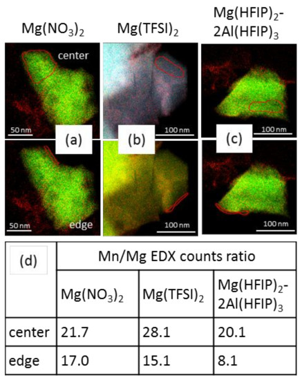
Figure 4.
STEM-EDX Mg + Mn maps of a magnesiated manganese spinel cathode material samples cycled for (a) 5 cycles in Mg(NO3)2, (b) 15 cycles until failure in Mg(TFSI)2/diglyme, and (c) 60 cycles until failure in Mg(HFIP)2 − 2Al(HFIP)3/diglyme; (d) table with Mn/Mg counts ratios, calculated from the marked central and edge areas of the particles.
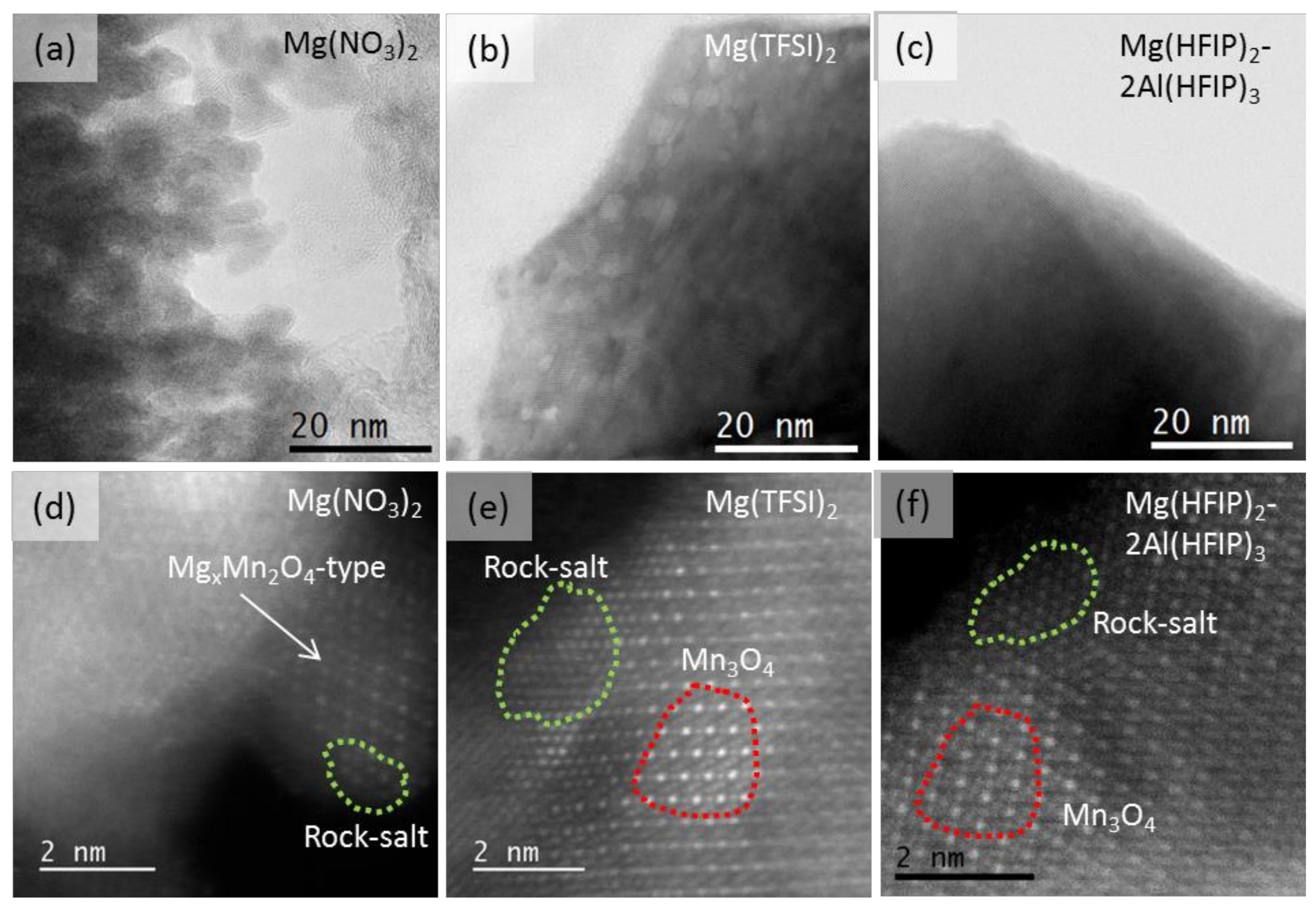
Cathodes materials’ microstructure and crystal structure changes on the atomic level upon cycling in the three different electrolytes are shown in Figure 5. Here, the Mg(NO3)2/diglyme-cycled sample microstructure has the most damaged appearance (Figure 5a). The spinel material has degraded upon 100 cycles from larger up to 300 nm single crystal particles into agglomerates of nanoparticles with disturbed crystallinity and sizes of about 5–10 nm (Figure 5a,d and Figure S2). The Mg(TFSI)2/diglyme-cycled sample that showed a very rapid capacity reduction in the first five cycles and failed after only 15 cycles retained a single crystal formation. The microstructure at the edges of the particle appears significantly etched and porous (Figure 5b). The Mg(HFIP)2 − 2Al(HFIP)3/diglyme-cycled material, where much better electrochemical behavior with more linear capacity drop throughout the cycling was observed (Figure 3b), revealed the least deformed microstructure with not many visible pores or defects after 60 cycles (Figure 5c).
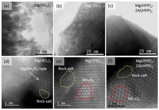
Figure 5.
STEM-BF and atomic resolution STEM-HAADF images of magnesiated spinel cathodes cycled in: (a,d) Mg(NO3)2 for 100 cycles; (b,e) Mg(TFSI)2/diglyme for 15 cycles; (c,f) Mg(HFIP)2 − 2Al(HFIP)3/diglyme for 60 cycles.
Thorough inspection of samples at the atomic resolution level showed similar patterns of structural degradation of LiMn2O4-type spinel structure for all applied electrolytes (Figure 5d–f). Atomic columns intensity patterns, such as in the areas marked by red and green dotted lines in Figure 5e,f, were observed in the large amounts in all three samples throughout the electron transparent areas. The green dotted lines mark the areas that correspond to the rock salt Mg/Mn mixed structure, while the red ones mark the STEM-HAADF contrast pattern of Mn3O4-type spinel.
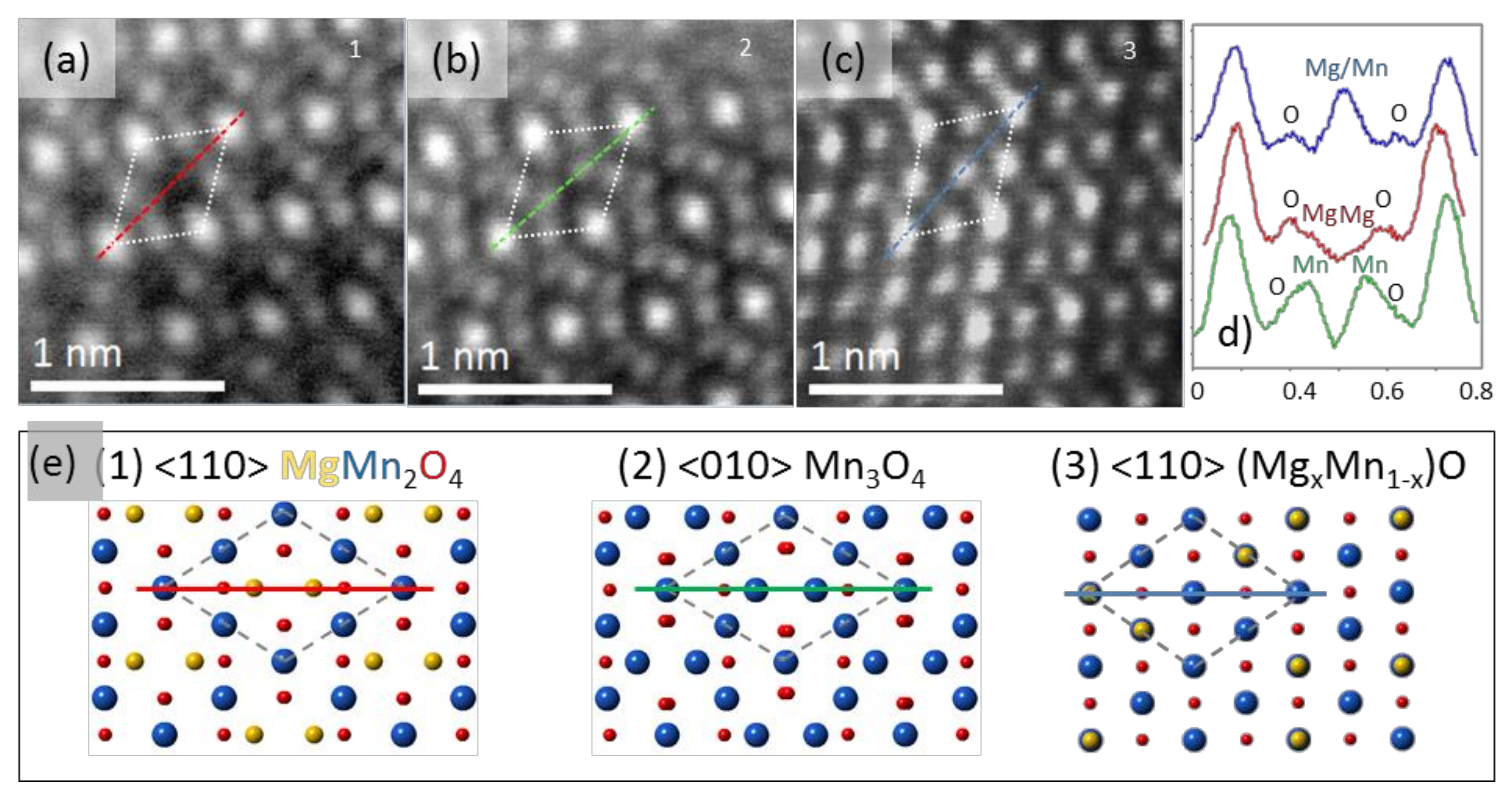
A more detailed presentation of all three crystal structures, i.e., MgxMn2O4, Mn3O4, and (MgxMn1-x)O, is given in Figure 6. The STEM-HAADF representative atomic resolution images (Figure 6a–c) were cut out from the adjacent areas near the edge of the particle in a single micrograph, taken from the sample cycled in aqueous electrolyte for five cycles. As it can be seen in the atomic structure sketches in Figure 6e and in the intensity profiles of all three structures plotted in Figure 6d, the changes in the atomic arrangement and interatomic distances in crystal structures can be monitored by observing the so-called Mn diamond configuration [30], marked by dashed lines in Figure 6. This configuration is visible in the <010> tetragonal spinel and <110> cubic spinel and cubic rock salt structural projections. In the nominal MgMn2O4 structure, the corners of the Mn diamond are occupied by the Mn atoms at 16d positions, while Mg occupies 8a sites. Changes in STEM-HAADF contrast that can be seen within the central part of the Mn diamond (Figure 6a–c) correspond to the initial Mg spinel structure being transformed into Mn3O4 and rock salt structures. In Mn3O4, the Mn atoms occupy the 8a positions in diamond configuration that are left open upon Mg leave (Figure 6b,e2). This is observed as the increased intensity at 8a sites in the center of the diamond configuration compared to that of MgMn2O4 (see intensity profiles in Figure 6d with respective colors). In rock salt, the diamond configuration exhibits only one strong contrast in the central octahedral site (Figure 6c,e3). Here, the transformation from the normal spinel proceeds via the insertion of the Mg cations into vacant 16c sites followed by the Frenkel defect-mediated shift of Mg from tetrahedral to octahedral sites [31].
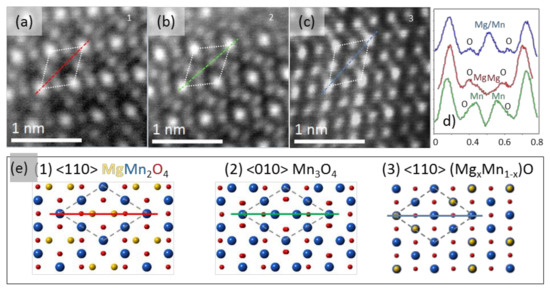
Figure 6.
STEM-HAADF cutouts from micrographs taken from a sample cycled for 5 cycles in water based Mg(NO3)2 electrolyte showing different atomic arrangements within cycled manganese spinel and corresponding atomic models of (a,e1) cubic MgMn2O4, (b,e2) tetragonal Mn3O4, and (c,e3) cubic MgxMn1-xO rock salt structures. In (d), three intensity line profiles taken along the lines with corresponding colors marked in (a–e) are given.
The majority of reported synthesized MgMn2O4 spinels possess tetragonal I41/amd symmetry, where Mn3+ ions at the octahedral sites are distorted by a cooperative Jahn–Teller effect. Only Truong and coworkers have reported on synthesis and electrochemical cycling of cubic MgMn2O4 in Mg(ClO4)2/acetonitrile and Mg(NO3)2 electrolytes [18,30]. In this study, the cubic Fd-3m LiMn2O4 spinel was used as a precursor in order to see the effect of magnesiation on the normal cubic spinel structure. XRD measurements of water-based electrolyte-cycled sample proved to be difficult due to the need for collecting the large amount of cycled material. Due to the specifics of material cycling that was employed in order to receive larger amount of cycled sample, the amount of magnesiated material in XRD measurements was not in accordance with ICP measurements. The latter was performed on a material cycled in smaller amounts in a way described in the experimental section. The observed magnesiated fraction possessed a cubic structure with a smaller unit cell parameter (from a = 8227 Å in pristine LiMn2O4, to a = 8174 Å in delithiated state, to a = 8163 Å upon magnesiation) compared to that of the LiMn2O4 spinel (Figure S3), which is in the agreement with recent studies. Therefore, for monitoring the local crystal structure changes after cycling to failure in each of the three electrolytes, the ratio of short (S) to long (L) diagonals of the Mn diamond configuration displayed in Figure 6 was calculated from the experimental STEM-HAADF images (Table 2) [30]. For comparison, the cubic and tetragonal structure end members’ ratios are also given. For the experimental measurements presented in Table 2, only areas with the MgMn2O4-like diamond configuration were considered in the STEM-HAADF images.
Table 2.
Measured short (S) and long (L) diagonal distances in the Mn diamond viewed in <010> tetragonal and in <110> cubic zone axis and their calculated S/L ratio for cubic MgMn2O4, tetragonal MgMn2O4, and all three samples cycled in different electrolytes. Values for diagonal lengths are given in Å. The error of experimental length determination was in the range pixel size of ±0.08 Å.
The obtained S/L ratio of 0.718 for Mg(NO3)2-cycled sample was the closest to the cubic structure values, which is in accordance with XRD measurements. Mg(TFSI)2/diglyme-cycled sample exhibited the most tetragonal distortion of the magnesiated spinel structure, while the Mg(HFIP)2 − 2Al(HFIP)2/diglyme-cycled sample values were around the middle value of two end members, with a slight tendency towards tetragonal. In the case of the latter sample, more Mg was inserted into the delithiated LiMn2O4 according to the ICP measurements (see Table 1), while the former sample showed good delithiation but poorer magnesiation behavior. In all samples, the diamond configuration measured in the areas of the Mn3O4 structure had tetragonal S/L ratios (S/L = 0.632), while the S/L ratios from the rock salt structure areas deviated from the expected cubic by approximately 50% towards tetragonal values (S/L = 0.695).
We applied STEM-EELS analysis to explore changes in Mn valence from the surface into the interior of the magnesiated manganese spinel particles upon cycling in three different electrolytes. Due to the variations in the chemical bonding and the environment of a specific atom, so-called chemical shift of the Mn L2,3 energy-loss edge onset is induced along with modifications in the near-edge fine structure (ELNES) of the EEL spectrum. While the valence numbers can be with some precautions calculated from the Mn L3/L2 peaks ratio [32], chemical shift of the edge onset allows for a quick way to monitor changes in the Mn valence. In order to keep the electron beam damage minimal, fast acquisition of EEL spectra during the line scan was applied.
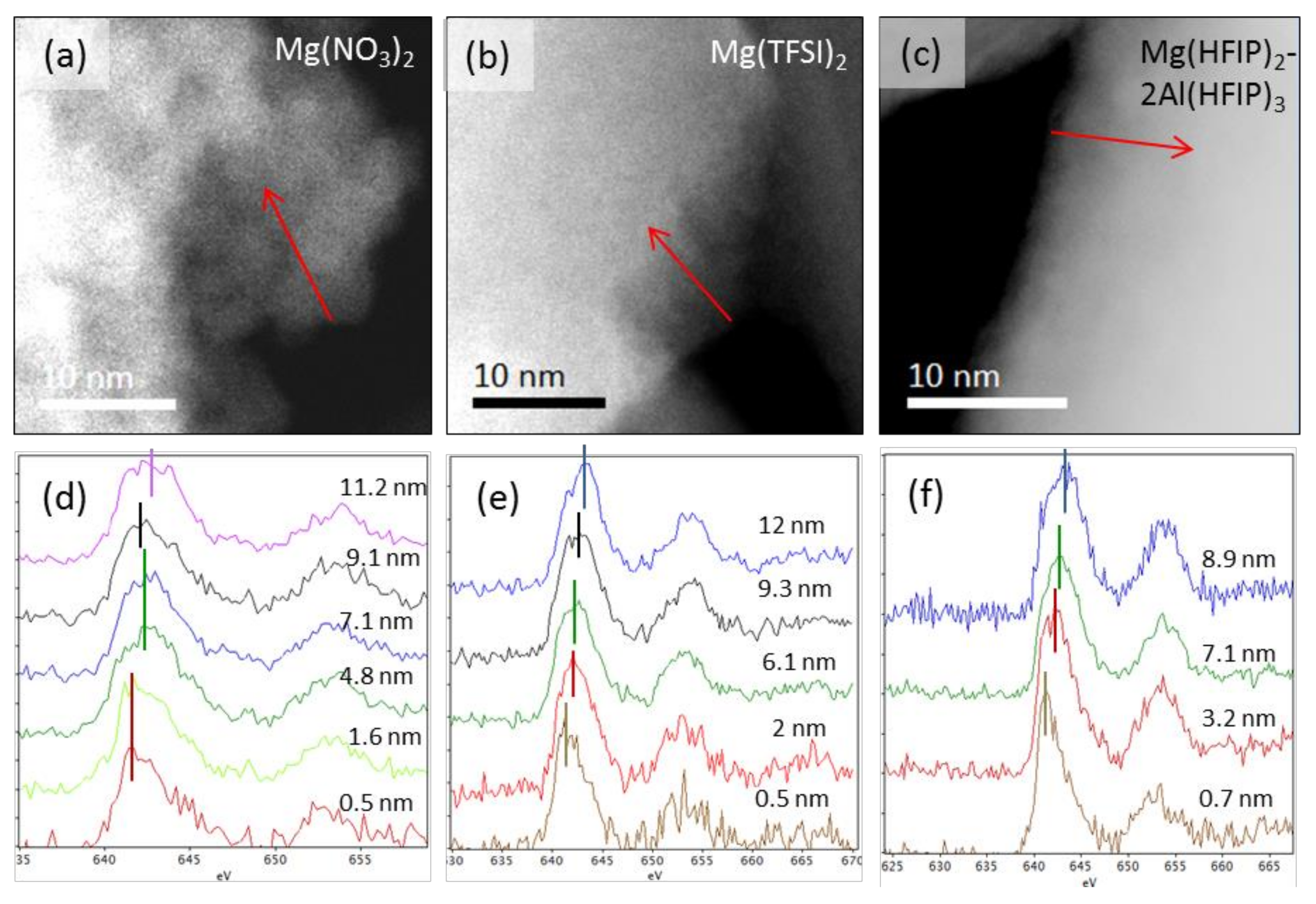
EEL spectra of Mn L2,3 edge revealed that in all three samples, the Mn L2,3 edge onset position experienced a chemical shift, which was observed up to the 15 nm depth into the particle’s interior (Figure 7). Please note that the positions of the Mn L3 peaks instead of edge onsets are marked for easier visual differentiation. Relying on peak positions for the determination of true chemical shift would lead to erroneous values due to the differences in ELNES fine structure of the edge, which depends on the Mn atom surrounding in the structure. Both non-aqueous electrolytes-cycled samples (Figure 7b,c,e,f) show gradual chemical shift towards higher valence states of Mn. The Mg(TFSI)2-cycled sample has reaches the chemical shift of 0.75 eV within 12.5 nm into particle’s depth on average with edge onset starting at 639.25 eV and finishing at 640 eV, while the Mg(HFIP)2 − 2Al(HFIP)3-cycled sample has reached the same chemical shift within 8.72 nm on average. The L3/L2 ratios for the area within first 15 nm particle depths in both samples were 2.44 and 2.7, respectively. These values correspond to mixed Mn2+/Mn3+ valences, with the Mg(TFSI)2-cycled sample having more Mn2+ and the Mg(HFIP)2 − 2Al(HFIP)3-cycled sample having more Mn3+ species [32]. This is in accordance with the observation of large amounts of Mn3O4 and Mg/Mn mixed rock salt structures by STEM-HAADF. The sample cycled in aqueous electrolyte, however, revealed rather random fluctuations of chemical shift of 0.5 eV within the whole analysis area due to the disintegrated microstructure described earlier (Figure 7a,d). The Mn L3/L2 edge onset position was lying between 639.75 eV and 640 eV, while the average L3/L2 ratio for the area of first 15 nm particle depths was 3.0. This corresponds as well to the mixture of Mn2+ and Mn3+ species; however, it implicates the highest Mn2+ amount among all three samples. The result corroborates the STEM-HAADF imaging data, where the aqueous sample demonstrated the most disintegrated microstructure.
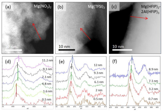
Figure 7.
STEM-HAADF images with marked position and direction of EELS line scans for cathode material samples cycled in (a) Mg(NO3)2, (b) Mg(TFSI)2, and (c) Mg(HFIP)2 − 2Al(HFIP)3 electrolytes. In (d,e,f), the corresponding plots of Mn L2,3 edge vs. distance from the particle’s surface into the interior are presented.
4. Conclusions
A commercial LiMn2O4 powder was used as a base material for a study of magnesium insertion into the structure from three different electrolytes. A water-based electrolyte was used for a model study on whether electrolytes with weak coordination of the magnesium cation support its insertion into the spinel structure. Additionally, two other electrolytes (Mg(TFSI)2/diglyme and Mg(Mg(HFIP)2 − 2Al(HFIP)3/diglyme) were used to probe magnesium insertion in the full cell configuration. The electrochemical characteristics obtained in an aqueous Mg(NO3)2 electrolyte suggest high activity and good reversibility of spinel sample; however, post mortem analysis reveals complete disintegration of particles with significant structural changes. As expected, cycling in the electrolyte with strong Mg2+ coordination shows that limited electrochemical activity and structural changes are present only on the surface of spinel particles. Electrochemical characteristics of magnesium insertion into the spinel structure from the Mg(HFIP)2 − 2Al(HFIP)3/diglyme electrolyte show low polarization and slow capacity fading. Core-shell, i.e., a difference between the outer and inner parts of the particle, is also observed within particles cycled in Mg(HFIP)2 − 2Al(HFIP)3/diglyme electrolyte, and both samples cycled in non-aqueous electrolytes show a significant difference between the core and shell Mn/Mg ratios. The only difference is that the Mg(HFIP)2 − 2Al(HFIP)3/diglyme-cycled material shows the least deformed microstructure. In all three cases, structural changes along with dissolution are the main degradation mechanisms due to the recrystallisation of spinel into a rock salt structure or into Mn3O4-type spinel.
Supplementary Materials
The following are available online at https://www.mdpi.com/article/10.3390/cryst11080984/s1, S1. STEM-EDX Mg and Mn maps of Aqua, TFSI, and HFIP samples; Figure S2. Magnesiated (MgxLi1-x)Mn2O4 structure after 5 cycles (STEM-HAADF images above) and after failure at 100 cycles (STEM-BF image below); Figure S3. XRD of delithiated LiMn2O4 and magnesiated (MgxLi1-x)Mn2O4.
Author Contributions
Conceptualization, A.R., E.T., A.R.-V. and R.D.; methodology, A.R., J.B. and E.T.; writing—original draft preparation, E.T. and R.D.; writing—review and editing, R.D.; project administration, A.R.-V. and R.D.; funding acquisition, A.R.-V. and R.D. All authors have read and agreed to the published version of the manuscript.
Funding
The research was supported by the Slovenian Research Agency (ARRS), research core funding P2-0393, and Honda R&D Europe.
Conflicts of Interest
The authors declare no conflict of interest.
References
- Matsui, M. Study on Electrochemically Deposited Mg Metal. J. Power Sources 2011, 196, 7048–7055. [Google Scholar] [CrossRef]
- Aurbach, D.; Lu, Z.; Schechter, A.; Gofer, Y.; Gizbar, H.; Turgeman, R.; Cohen, Y.; Moshkovich, M.; Levi, E. Prototype Systems for Rechargeable Magnesium Batteries. Nature 2000, 407, 724–727. [Google Scholar] [CrossRef] [PubMed]
- Muldoon, J.; Bucur, C.B.; Gregory, T. Fervent Hype behind Magnesium Batteries: An Open Call to Synthetic Chemists-Electrolytes and Cathodes Needed. Angew. Chem. Int. Ed. 2017, 56, 12064–12084. [Google Scholar] [CrossRef] [PubMed]
- Dominko, R.; Bitenc, J.; Berthelot, R.; Gauthier, M.; Pagot, G.; Di Noto, V. Magnesium Batteries: Current Picture and Missing Pieces of the Puzzle. J. Power Sources 2020, 478, 229027. [Google Scholar] [CrossRef]
- Bitenc, J.; Pirnat, K.; Bančič, T.; Gaberšček, M.; Genorio, B.; Vitanova, A.R.; Dominko, R. Anthraquinone-Based Polymer as Cathode in Rechargeable Magnesium Batteries. ChemSusChem 2015, 8, 4128–4132. [Google Scholar] [CrossRef]
- Kim, H.S.; Arthur, T.S.; Allred, G.D.; Zajicek, J.; Newman, J.G.; Rodnyansky, A.E.; Oliver, A.G.; Boggess, W.C.; Muldoon, J. Structure and Compatibility of a Magnesium Electrolyte with a Sulphur Cathode. Nat. Commun. 2011, 2, 427. [Google Scholar] [CrossRef]
- Nazar, L.; Sun, X.; Duffort, V.; Bonnick, P.; Rong, Z.; Liu, M.; Persson, K.; Ceder, G. A High Capacity Thiospinel Cathode for Mg Batteries. Energy Environ. Sci. 2016, 9, 2273–2277. [Google Scholar] [CrossRef]
- Sun, X.; Bonnick, P.; Nazar, L.F. Layered TiS2 Positive Electrode for Mg Batteries. ACS Energy Lett. 2016, 1, 297–301. [Google Scholar] [CrossRef]
- Canepa, P.; Gautam, G.S.; Malik, R.; Jayaraman, S.; Rong, Z.; Zavadil, K.R.; Persson, K.; Ceder, G. Understanding the Initial Stages of Reversible Mg Deposition and Stripping in Inorganic Nonaqueous Electrolytes. Chem. Mater. 2015, 27, 3317–3325. [Google Scholar] [CrossRef] [Green Version]
- Levi, E.; Gershinsky, G.; Aurbach, D.; Isnard, O.; Ceder, G. New Insight on the Unusually High Ionic Mobility in Chevrel Phases. Chem. Mater. 2009, 21, 1390–1399. [Google Scholar] [CrossRef]
- Gu, Y.; Katsura, Y.; Yoshino, T.; Takagi, H.; Taniguchi, K. Rechargeable Magnesium-Ion Battery Based on a TiSe2-Cathode with d-p Orbital Hybridized Electronic Structure. Sci. Rep. 2015, 5, 12486. [Google Scholar] [CrossRef] [PubMed] [Green Version]
- Liu, B.; Luo, T.; Mu, G.; Wang, X.; Chen, D.; Shen, G. Rechargeable Mg-Ion Batteries Based on WSe2 Nanowire Cathodes. ACS Nano 2013, 7, 8051–8058. [Google Scholar] [CrossRef] [PubMed]
- Huie, M.M.; Bock, D.C.; Takeuchi, E.S.; Marschilok, A.C.; Takeuchi, K.J. Cathode Materials for Magnesium and Magnesium-Ion Based Batteries. Coord. Chem. Rev. 2015, 287, 15–27. [Google Scholar] [CrossRef] [Green Version]
- Ling, C.; Zhang, R.; Mizuno, F. Quantitatively Predict the Potential of MnO2 Polymorphs as Magnesium Battery Cathodes. ACS Appl. Mater. Interfaces 2016, 8, 4508–4515. [Google Scholar] [CrossRef]
- Sinha, N.N.; Munichandraiah, N. Electrochemical Conversion of LiMn2O4 to MgMn2O4 in Aqueous Electrolytes. Electrochem. Solid-State Lett. 2008, 11, F23. [Google Scholar] [CrossRef]
- Yuan, C.; Zhang, Y.; Pan, Y.; Liu, X.; Wang, G.; Cao, D. Investigation of the Intercalation of Polyvalent Cations (Mg2+, Zn2+) into λ-MnO2 for Rechargeable Aqueous Battery. Electrochim. Acta 2014, 116, 404–412. [Google Scholar] [CrossRef]
- Kim, C.; Phillips, P.J.; Key, B.; Yi, T.; Nordlund, D.; Yu, Y.-S.S.; Bayliss, R.D.; Han, S.-D.D.; He, M.; Zhang, Z.; et al. Direct Observation of Reversible Magnesium Ion Intercalation into a Spinel Oxide Host. Adv. Mater. 2015, 27, 3377–3384. [Google Scholar] [CrossRef]
- Truong, Q.D.; Devaraju, M.K.; Tran, P.D.; Gambe, Y.; Nayuki, K.; Sasaki, Y.; Honma, I. Unravelling the Surface Structure of MgMn2O4 Cathode Materials for Rechargeable Mg-Ion Battery. Chem. Mater. 2017, 29, 6245–6251. [Google Scholar] [CrossRef]
- Herb, J.T.; Nist-Lund, C.A.; Arnold, C.B. A Fluorinated Alkoxyaluminate Electrolyte for Magnesium-Ion Batteries. ACS Energy Lett. 2016, 1, 1227–1232. [Google Scholar] [CrossRef]
- van Aken, P.A.; Liebscher, B. Quantification of Ferrous/Ferric Ratios in Minerals: New Evaluation Schemes of Fe L23electron Energy-Loss near-Edge Spectra. Phys. Chem. Miner. 2002, 29, 188–200. [Google Scholar] [CrossRef]
- Matwiyoff, N.A.; Taube, H. Direct Determination of the Solvation Number of Magnesium(II) Ion in Water, Aqueous Acetone, and Methanolic Acetone Solutions. J. Am. Chem. Soc. 1968, 90, 2796–2800. [Google Scholar] [CrossRef]
- Nam, K.W.; Kim, S.; Lee, S.; Salama, M.; Shterenberg, I.; Gofer, Y.; Kim, J.-S.; Yang, E.; Park, C.S.; Kim, J.-S.; et al. The High Performance of Crystal Water Containing Manganese Birnessite Cathodes for Magnesium Batteries. Nano Lett. 2015, 15, 4071–4079. [Google Scholar] [CrossRef] [PubMed]
- Pan, B.; Feng, Z.; Sa, N.; Han, S.-D.; Ma, Q.; Fenter, P.; Vaughey, J.T.; Zhang, Z.; Liao, C. Advanced Hybrid Battery with a Magnesium Metal Anode and a Spinel LiMn2O4 Cathode. Chem. Commun. 2016, 52, 9961–9964. [Google Scholar] [CrossRef]
- Zhao-Karger, Z.; Gil Bardaji, M.E.; Fuhr, O.; Fichtner, M. A New Class of Non-Corrosive, Highly Efficient Electrolytes for Rechargeable Magnesium Batteries. J. Mater. Chem. A 2017, 5, 10815–10820. [Google Scholar] [CrossRef]
- Rajput, N.N.; Seguin, T.J.; Wood, B.M.; Qu, X.; Persson, K.A. Elucidating Solvation Structures for Rational Design of Multivalent Electrolytes—A Review. Top. Curr. Chem. 2018, 376, 19. [Google Scholar] [CrossRef] [Green Version]
- Edström, K.; Gustafsson, T.; Thomas, J.O. The Cathode-Electrolyte Interface in the Li-Ion Battery. Electrochim. Acta 2004, 50, 397–403. [Google Scholar] [CrossRef]
- Aurbach, D.; Markovsky, B.; Rodkin, A.; Levi, E.; Cohen, Y.S.; Kim, H.J.; Schmidt, M. On the Capacity Fading of LiCoO2 Intercalation Electrodes: The Effect of Cycling, Storage, Temperature, and Surface Film Forming Additives. Electrochim. Acta 2002, 47, 4291–4306. [Google Scholar] [CrossRef]
- Cabana, J.; Kwon, B.J.; Hu, L. Mechanisms of Degradation and Strategies for the Stabilization of Cathode-Electrolyte Interfaces in Li-Ion Batteries. Acc. Chem. Res. 2018, 51, 299–308. [Google Scholar] [CrossRef]
- Sun, X.; Duffort, V.; Mehdi, B.L.; Browning, N.D.; Nazar, L.F. Investigation of the Mechanism of Mg Insertion in Birnessite in Non-Aqueous and Aqueous Rechargeable Mg-Ion Batteries. Chem. Mater. 2015, 28, 534–542. [Google Scholar] [CrossRef]
- Truong, Q.D.; Kobayashi, H.; Nayuki, K.; Sasaki, Y.; Honma, I. Atomic-Scale Observation of Phase Transition of MgMn2O4 Cubic Spinel upon the Charging in Mg-Ion Battery. Solid State Ionics 2020, 344, 115136. [Google Scholar] [CrossRef]
- Ryoo, H.; Bae, H.B.; Kim, Y.M.; Kim, J.G.; Lee, S.; Chung, S.Y. Frenkel-Defect-Mediated Chemical Ordering Transition in a Li-Mn-Ni Spinel Oxide. Angew. Chem. Int. Ed. 2015, 54, 7963–7967. [Google Scholar] [CrossRef] [PubMed]
- Tan, H.; Verbeeck, J.; Abakumov, A.; Van Tendeloo, G. Oxidation State and Chemical Shift Investigation in Transition Metal Oxides by EELS. Ultramicroscopy 2012, 116, 24–33. [Google Scholar] [CrossRef]

Publisher’s Note: MDPI stays neutral with regard to jurisdictional claims in published maps and institutional affiliations. |
© 2021 by the authors. Licensee MDPI, Basel, Switzerland. This article is an open access article distributed under the terms and conditions of the Creative Commons Attribution (CC BY) license (https://creativecommons.org/licenses/by/4.0/).