Article

Two-Dimensional Distributed Transmission-Line Models for Broadband Full-Tensor Anisotropic Acoustic Metamaterials Based on Transformation Acoustics

Graduate School of Science and Engineering, Kagoshima University, 1-21-40 Korimoto, Kagoshima-shi 890-0065, Japan
*
Author to whom correspondence should be addressed.
Crystals 2022, 12(11), 1557; https://doi.org/10.3390/cryst12111557
Submission received: 1 October 2022 / Revised: 20 October 2022 / Accepted: 21 October 2022 / Published: 31 October 2022

Abstract

:
We propose the design method for broadband acoustic metamaterials based on the concept of transformation acoustics. Two-dimensional distributed transmission-line (TL) models for full-tensor anisotropic electromagnetic metamaterials are applied to full-tensor anisotropic acoustic metamaterials and the design formulas are shown to uniquely determine the structural parameters of the unit cells. Two-dimensional acoustic waveguide unit cell structures for realizing the TL models are proposed and an acoustic carpet cloak and an acoustic illusion medium are designed according to the introduced theory. The complex sound pressure distributions in the acoustic waveguides of the unit cells are calculated by full-wave simulations to verify the validity of the proposed method, and the broadband operations of the designed carpet cloak and illusion medium are confirmed from the results.

1. Introduction

In the field of electromagnetic waves, design methods with equivalent circuit models based on the transmission-line approach [1] have been adopted to designs of electromagnetic metamaterials since the approach can abstract Maxwell’s equations and leads to physical insights and rigorous designs. In particular, these have widely been used for the designs of electromagnetic metamaterials having negative refractive index characteristics [2,3,4,5,6]. Furthermore, two-dimensional (2-D) equivalent circuit models for full-tensor anisotropic metamaterials [7,8] have been proposed and have been introduced to the design of metamaterials based on the concept of transformation electromagnetics [9] that can realize invisible cloaks [9,10,11,12,13,14,15,16,17,18,19,20,21,22], carpet cloaks [7,8,21,23,24,25,26,27,28,29,30], and illusion media [31,32]. Those lumped circuit elements independently correspond to the permittivity and the permeability tensor components and, therefore, the models can rigorously design the unit cells of the full-tensor anisotropic metamaterials without resorting to many calculations by simulators that are one of the issues in the conventional design methods. The broadband operations can also be achieved due to the intrinsic nature of non-resonant. Furthermore, 2-D distributed transmission-line (TL) models have been proposed [8]. The characteristic impedance and the line length can be determined uniquely by substituting the lumped circuit elements in the 2-D equivalent circuit models for the design formulas and, therefore, we can easily implement metamaterials based on transformation electromagnetics with planar structures. The validity and the usefulness have also been demonstrated experimentally [8,32].
Recently, the theory of the 2-D equivalent circuit models for full-tensor anisotropic electromagnetic metamaterials has been extended to acoustic metamaterials [33,34] in order to realize acoustic invisible cloaks [21,35,36,37,38,39,40,41,42,43,44,45,46,47], acoustic carpet cloaks [33,48,49,50,51,52,53,54,55,56], or acoustic illusion media [34,57,58,59,60] based on the concept of transformation acoustics [35]. As is the same in the case of the electromagnetic metamaterials, the conventional design methods have issues like many calculations for designing the unit cell structures or narrowband characteristics, but the models introduced from the electromagnetic metamaterials can solve these simultaneously. So far, the correspondences between the lumped circuit elements and acoustic material parameters (the mass density tensor and the balk modulus) have been revealed [33] and the broadband operations of an acoustic carpet cloak and an acoustic illusion medium have been confirmed by circuit simulations [33,34]; however, the 2-D distributed TL models have yet to be introduced to acoustic metamaterials.
In this paper, we introduce the 2-D distributed TL models for full-tensor anisotropic electromagnetic metamaterials to the design of full-tensor anisotropic acoustic in order to theoretically determine the structural parameters of the unit cells and realize acoustic metamaterials based on transformation acoustics. In Section 2, we recall the theory of 2-D equivalent circuit models for acoustic metamaterials, and the 2-D distributed TL models for electromagnetic metamaterials, and update the design formulas of the TL models in order to determine the structural parameters of unit cells constituting acoustic metamaterials based on transformation acoustics. We also propose 2-D anisotropic acoustic waveguide unit cell structures and determine the waveguide widths and lengths for realizing an acoustic carpet cloak and an illusion medium as examples. In Section 3, the complex sound pressure distributions in those waveguides are calculated by full-wave simulations in order to confirm the broadband operations and the validity of the proposed design theory. In Section 4, this paper is concluded.

2. Methods

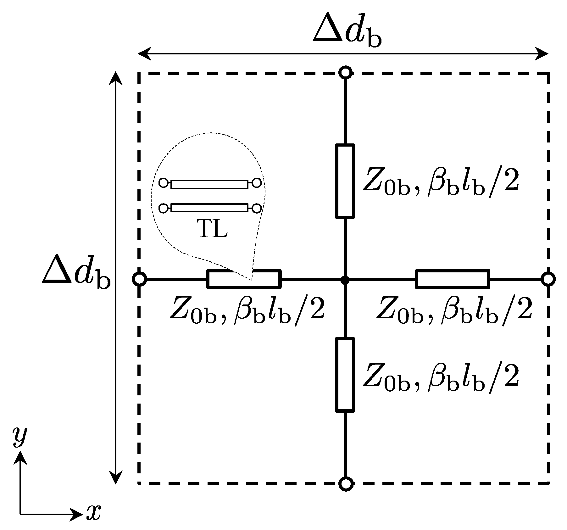
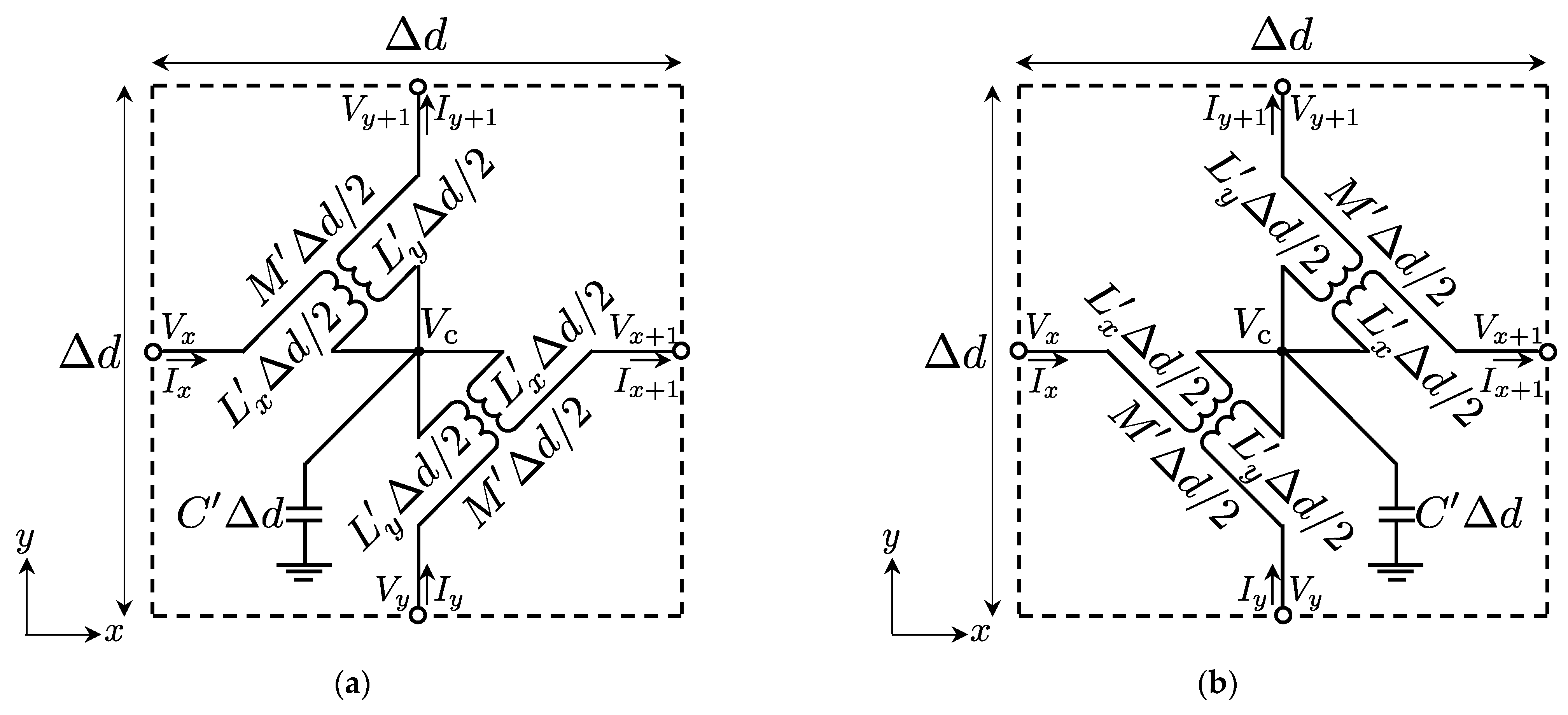
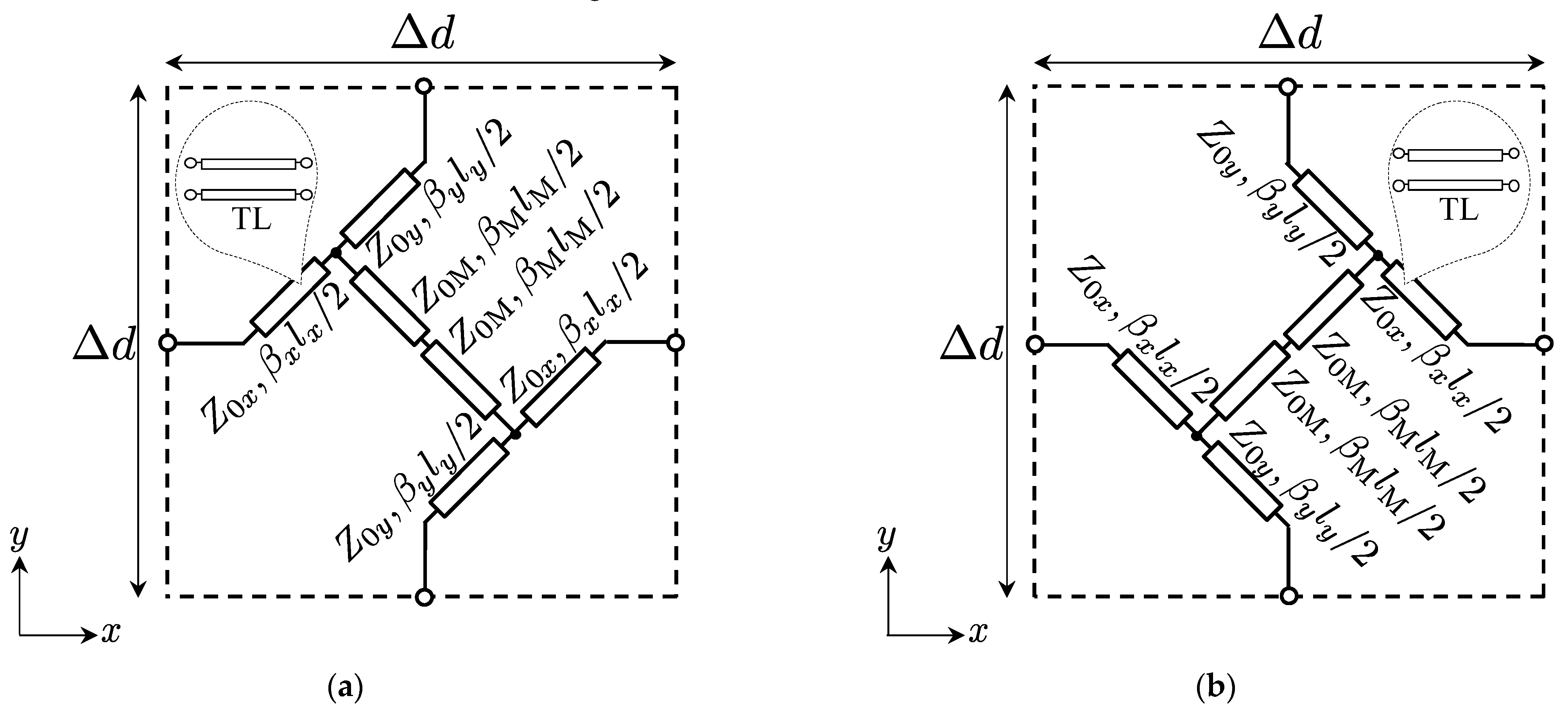
2.1. Design Formulas

Firstly, we recall the theory of 2-D equivalent circuit models for full-tensor anisotropic acoustic metamaterials (see Figure 1a,b) [33] and show the relations of material parameters and circuit parameters. According to the references of [7,8,33], defining the voltage and current vectors and the 2-D equivalent circuit models of Figure 1a,b as V = [Vx, Vx+1, Vy, Vy+1] and I = [Ix, −Ix+1, Iy, −Iy+1], we can obtain those circuit equations as shown in the left column of Table 1 from Kirchhoff’s voltage and current laws. On the other hand, Maxwell’s equations and acoustic equations in the 2-D Cartesian coordinate system with z invariance can be written as in the center and the right columns of Table 1 by assuming z-polarized TE waves or acoustic waves in a full-tensor anisotropic metamaterials and time harmonic variation, respectively. Then, considering the correspondences of voltages, currents, electric fields, magnetic fields, scalar pressures, and fluid velocities, as shown in Table 2, we can obtain the following relations [7,8,33] between the circuit parameters per unit length (Lx, Ly, M′, and C′), the parameters of electromagnetic metamaterials (μxx, μxy = μyx, μyy, and εz), and the parameters of acoustic metamaterials (ρxx, ρxy = ρyx, ρyy, and K′):
( L x M M L y ) ( ρ x x ρ x y ρ y x ρ y y ) ( μ y y μ y x μ x y   μ x x )
C 1 K ε z
where the upper signs correspond to the case of Figure 1a (ρxy = ρyx < 0) and the lower signs correspond to the case of Figure 1b (ρxy = ρyx > 0). Moreover, according to the concept of transformation acoustics [35], the mass density tensor (ρ′) and the bulk modulus (K′) for mimicking transformed coordinate system can be calculated from the following formulas:
ρ = ( det A ) ( A T ) 1 ρ A 1
K = ( det A ) K
where A is the Jacobian matrix, and ρ and K are the mass density and the bulk modulus for mimicking the original coordinate system, respectively.
Secondly, in order to theoretically determine the unit cell structures and realize broadband acoustic metamaterials based on transformation acoustics, we recall the design formulas of 2-D distributed TL models for full-tensor anisotropic electromagnetic metamaterials (see Figure 2a,b) [8], and extend the theory to acoustic metamaterials. The design formulas of the TL models for the case with electromagnetic metamaterials can be written as
L x M = 2 Z 0 x ω Δ d tan β l 2
L y M = 2 Z 0 y ω Δ d tan β l 2
M = 2 ω Δ d Z 0 M 2 ( Y 0 x + Y 0 y ) tan β l 2 + Z 0 M ( cosec β M l M cot β M l M ) cos 2 β l 2 + Z 0 M ( Y 0 x + Y 0 y ) sin β l cot β M l M Z 0 M 2 ( Y 0 x + Y 0 y ) 2 sin 2 β l 2
C = 1 ω Δ d { ( Y 0 x + Y 0 y ) sin β l cos β M l M + Y 0 M cos 2 β l 2 sin β M l M Z 0 M ( Y 0 x + Y 0 y ) 2 sin 2 β l 2 }
and according to the reference of [8], these can be obtained by comparing Z-parameters of the equivalent circuit models with those of the TL models. βl = βxlx = βyly is also assumed to solve these formulas simultaneously. Then, substituting (1) and (2) for (5)–(8), we can obtain the following design formulas for acoustic metamaterials that are extended from those for electromagnetic metamaterials:
ρ x x ± ρ x y = 2 Z 0 x ω Δ d tan β l 2
ρ y y ± ρ x y = 2 Z 0 y ω Δ d tan β l 2
ρ x y = ρ y x = 2 ω Δ d Z 0 M 2 ( Y 0 x + Y 0 y ) tan β l 2 + Z 0 M ( cosec β M l M cot β M l M ) cos 2 β l 2 + Z 0 M ( Y 0 x + Y 0 y ) sin β l cot β M l M Z 0 M 2 ( Y 0 x + Y 0 y ) 2 sin 2 β l 2
1 K = 1 ω Δ d { ( Y 0 x + Y 0 y ) sin β l cos β M l M + Y 0 M cos 2 β l 2 sin β M l M Z 0 M ( Y 0 x + Y 0 y ) 2 sin 2 β l 2 }
The upper signs of (9)–(11) correspond to the case of Figure 2a (ρxy = ρyx < 0) and the lower signs correspond to the case of Figure 2b (ρxy = ρyx > 0). It is seen from these formulas that we can uniquely determine the characteristic impedances (Z0x, Z0y, Z0M) and the electrical lengths (βl and βMlM) for acoustic metamaterials.

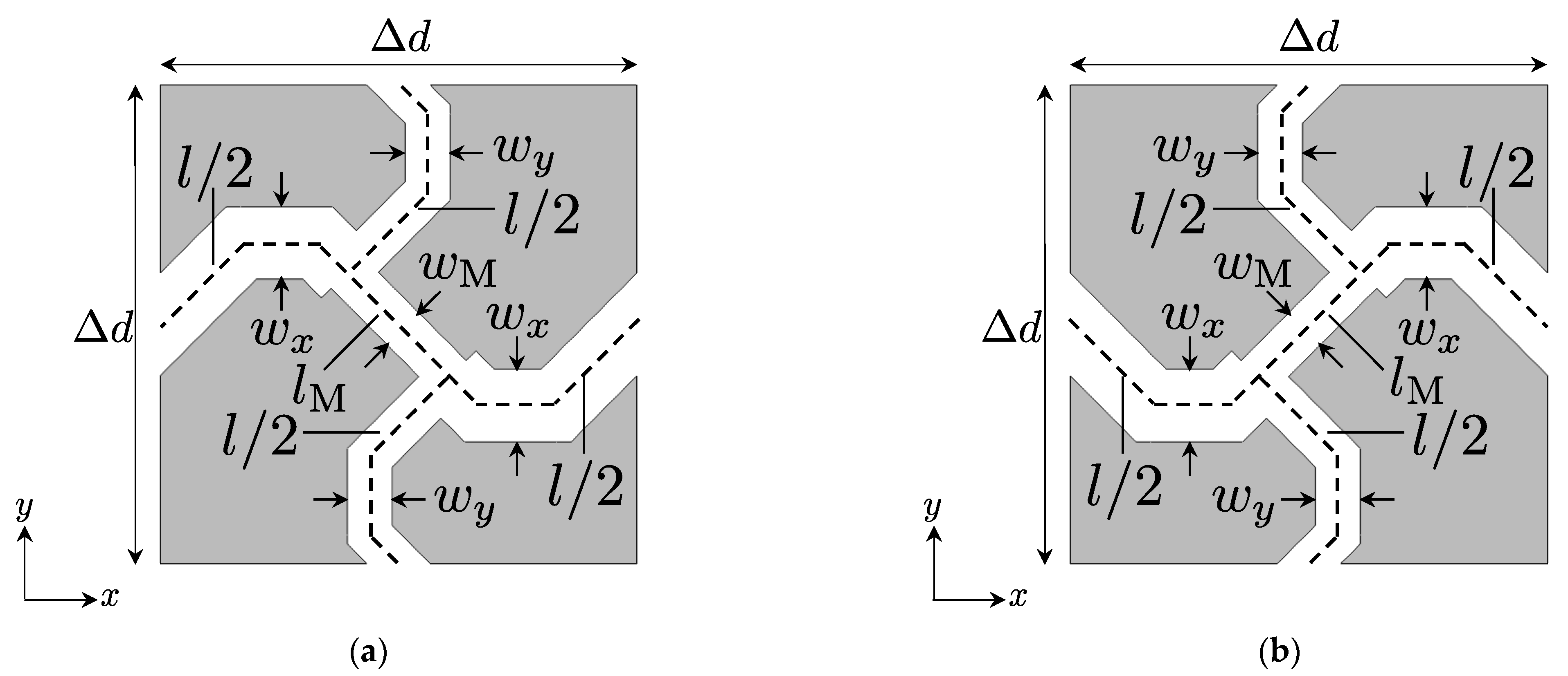
2.2. Proposed Acoustic Waveguide Unit Cell Structures

Figure 3a,b shows the proposed 2-D acoustic waveguide unit structures for full-tensor anisotropic acoustic metamaterials and Figure 4a,b is for the background medium to be connected to Figure 3a,b, respectively. Furthermore, these waveguides are formed in the rigid body and are filled with the air. wx, wy, wM, and wb are the waveguide widths, l (=lx = ly), lM, and lb are the waveguide lengths, and Δd and Δdb (=Δd) are the waveguide unit cell lengths. The waveguide widths can be determined as the following formulas:
w x = Z 0 b Z 0 x w b , w y = Z 0 b Z 0 y w b , w M = Z 0 b Z 0 M w b
where Z0b is the characteristic impedance of the 2-D distributed TLs for the background medium shown in Figure 5. The ratio of the characteristic impedances can be obtained from (9)–(12). On the other hand, the waveguide lengths can be calculated with
l = 2 ϕ l b , l M = 2 ϕ M l b
ϕ and ϕM are values of electrical lengths normalized by kbΔdb (kb is the wavenumber for the background medium) and represent the solutions of βl/kbΔdb and βMlM/kbΔdb obtained from (9)–(12), respectively. 2 denotes the 2-D effect of the unit cell structures [1,8].

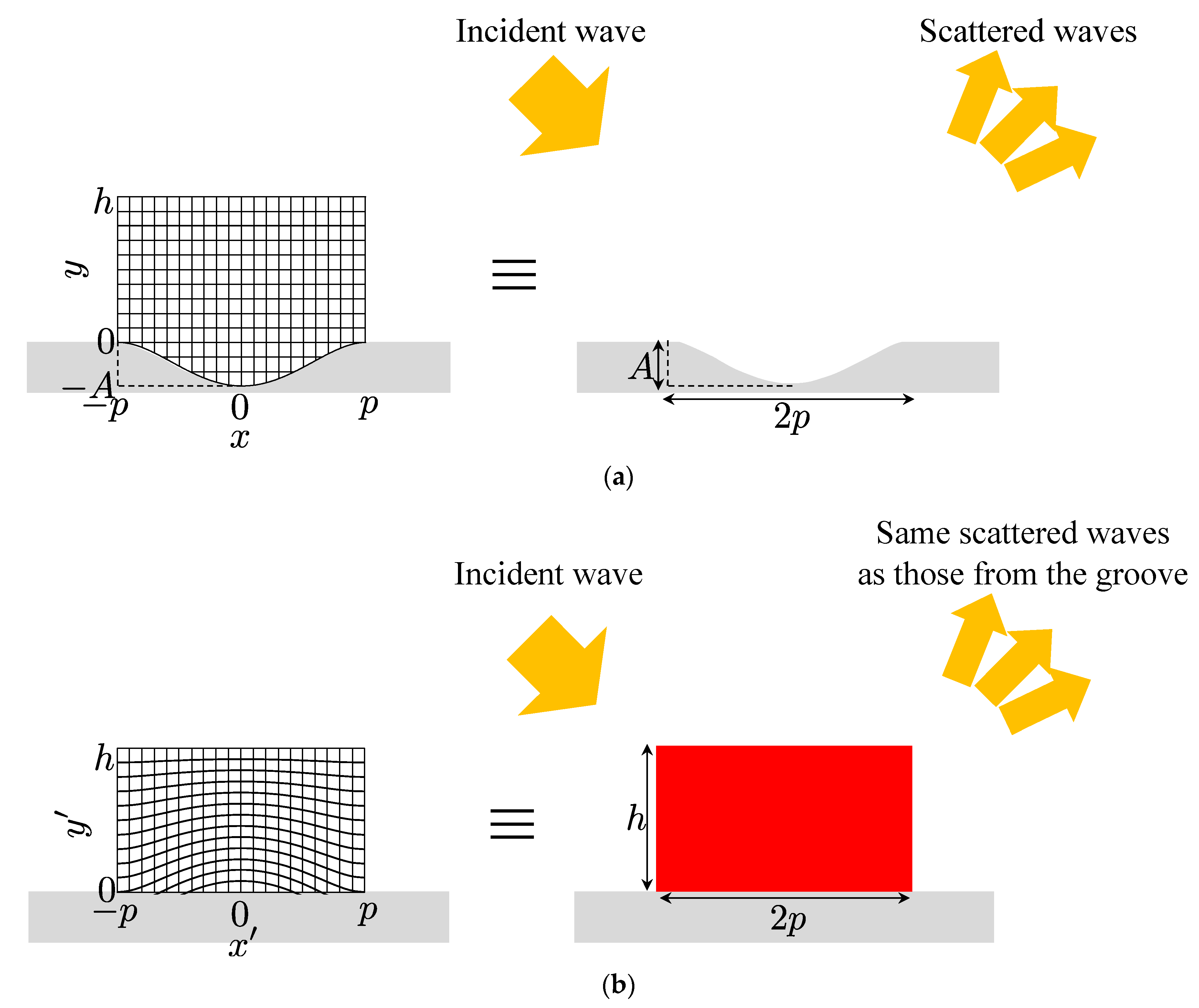
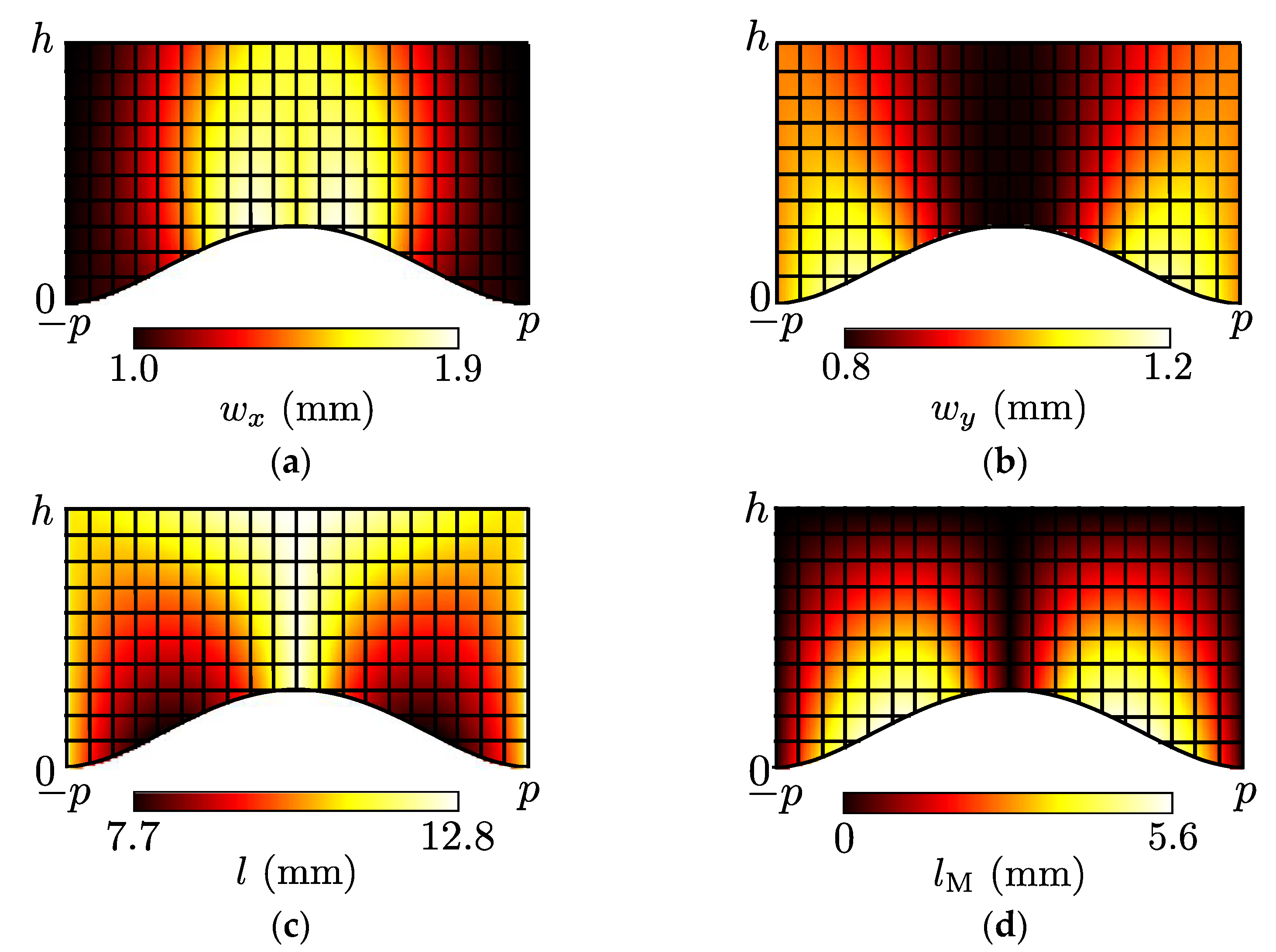
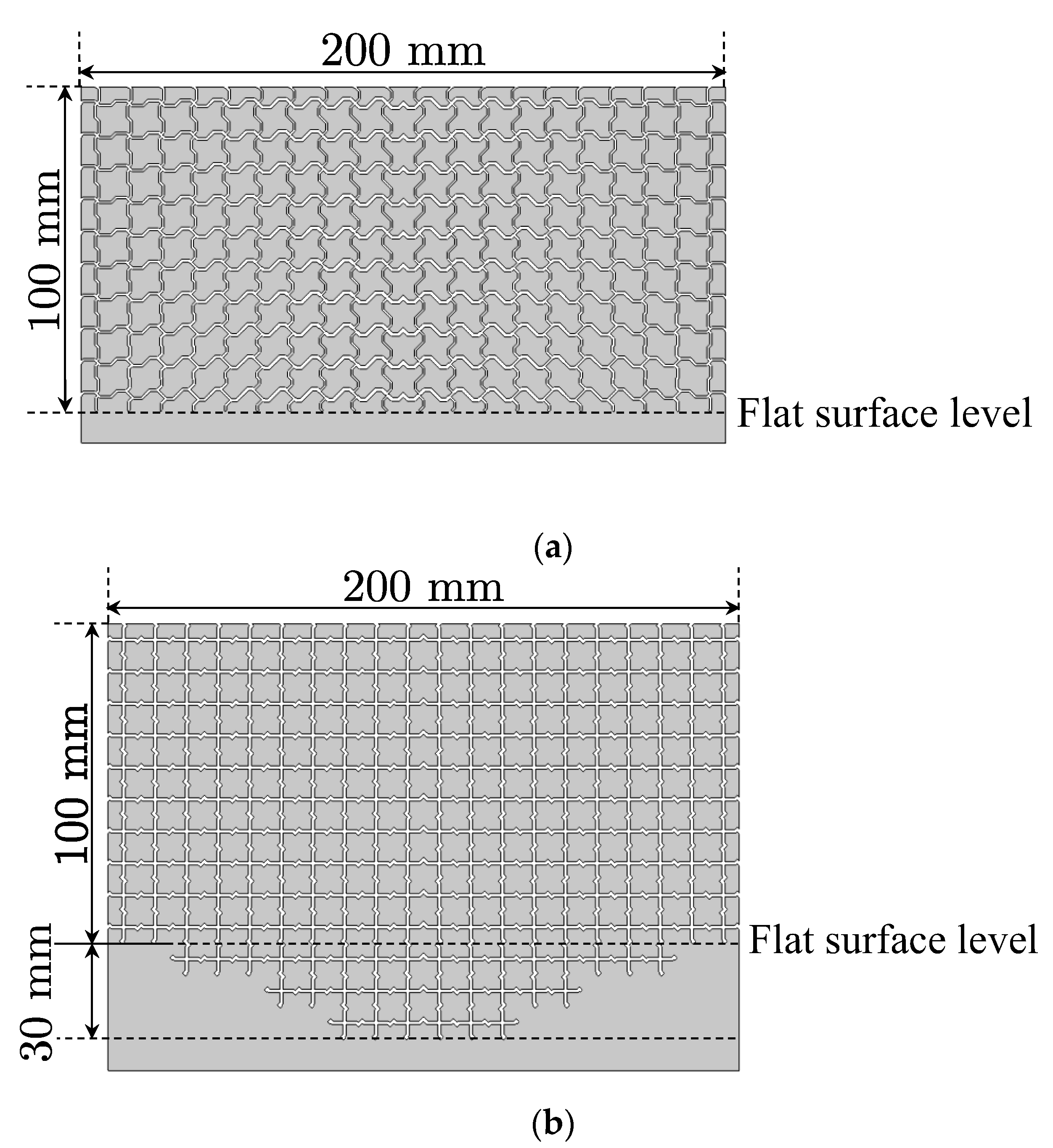
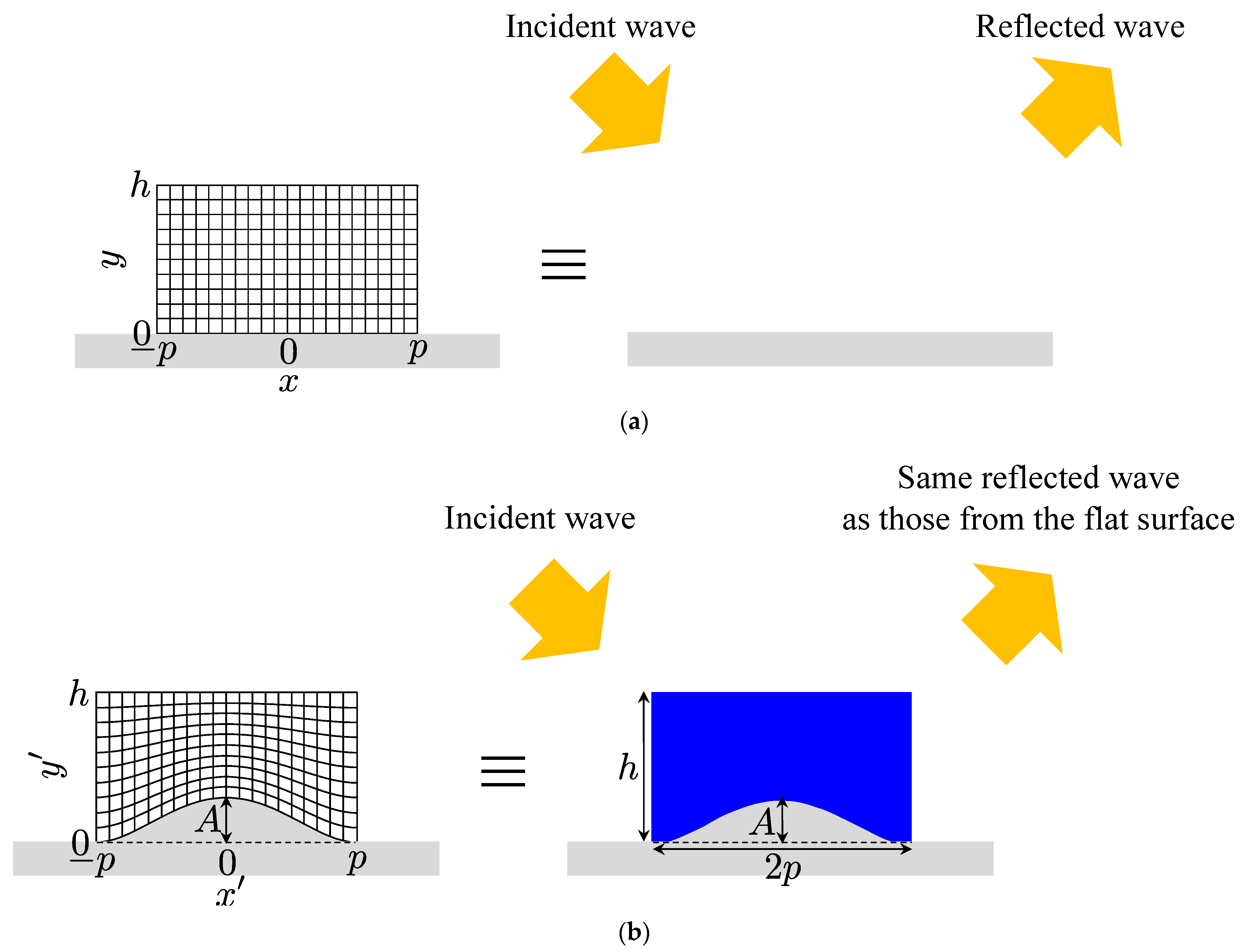
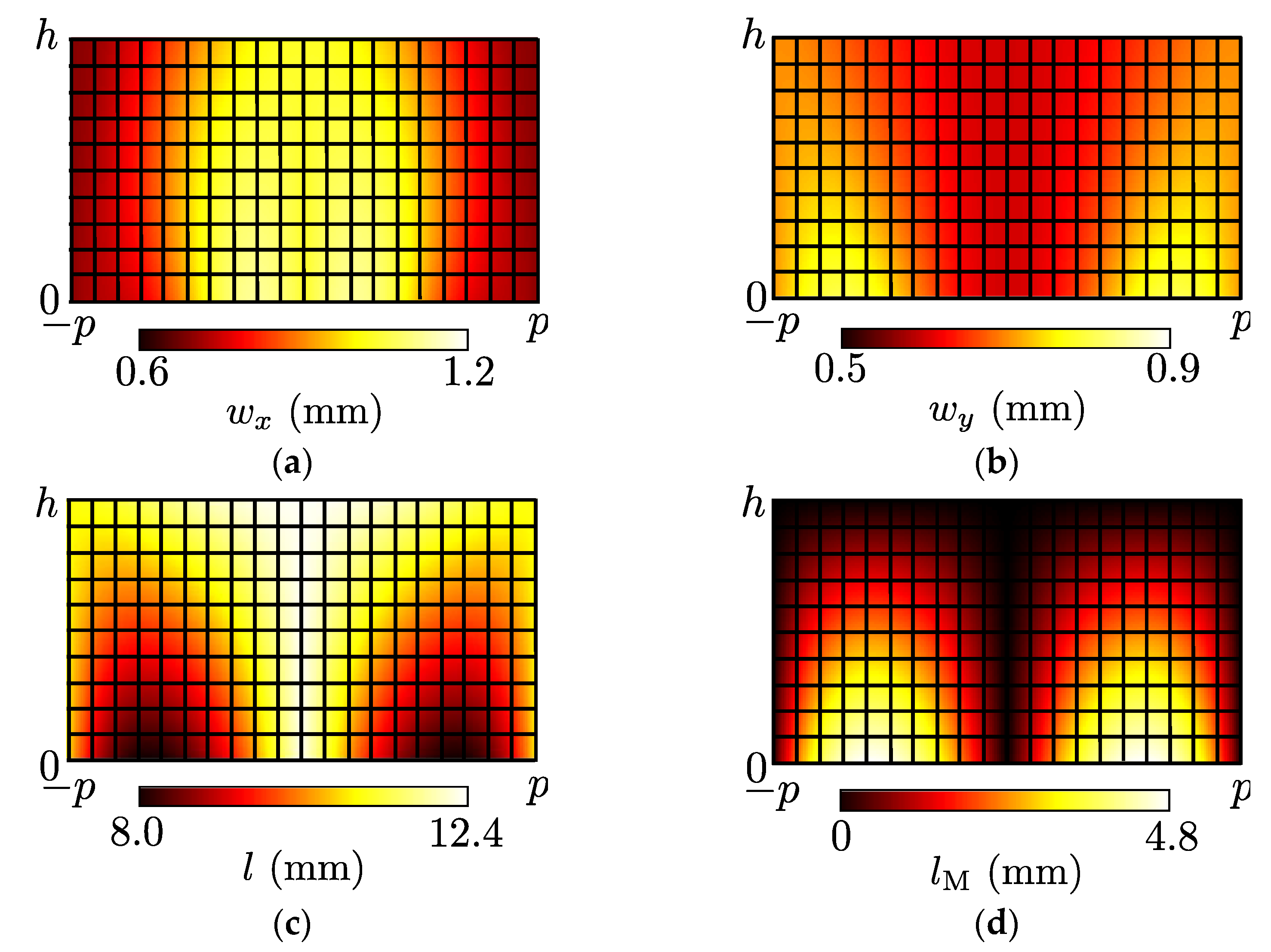
2.3. Design of an Acoustic Carpet Cloak and an Illusion Medium

Here, we design an acoustic carpet cloak for hiding a bump on a flat surface of Figure 6 [33] and an acoustic illusion medium for mimicking a groove on a flat surface of Figure 7 [34] to show the design examples with the proposed unit cell structures in the previous subsection. Incidentally, materials of the flat surface, the bump, and the groove are assumed to the rigid body in the following design.
We first consider defining the original coordinate systems, such as Figure 6a and Figure 7a, and transforming those to Figure 6b and Figure 7b, respectively. These transformation formulas are chosen as [33,34]
x = x , y = y + A ( 1 y h ) { 1 ( x p ) 2 } 2
x = x , y = y + A { 1 ( x p ) 2 } 2 h + A { 1 ( x p ) 2 } 2 h ,
respectively, and A, h, and p are selected as 30 mm, 100 mm, and 100 mm with Δd = Δdb = 10 mm, in the following, for simplicity.
Next, we obtained Z0b/Z0x, Z0b/Z0y, ϕ, and ϕM by using (3), (4), (9)–(12), (15), and (16) with Z0M/Z0b = 1.061 (carpet cloak case) or 1.500 (illusion medium case), and calculated wx, wy, l, and lM from (13) and (14) with wb = 1.0 mm and lb = 11 mm. Figure 8 and Figure 9 show the results for the acoustic carpet cloak case (wM = 0.943 mm) and the acoustic illusion medium case (wM = 0.667 mm), respectively, and these are determined by considering the feasibility. Furthermore, the designed acoustic carpet cloak and illusion medium are illustrated in Figure 10a and Figure 11a. We carry out the full-wave simulations and compare those results with the cases of the flat surface (see Figure 10b), the bump (see Figure 10c), and the groove (see Figure 11b) in the next section.

3. Results and Discussion

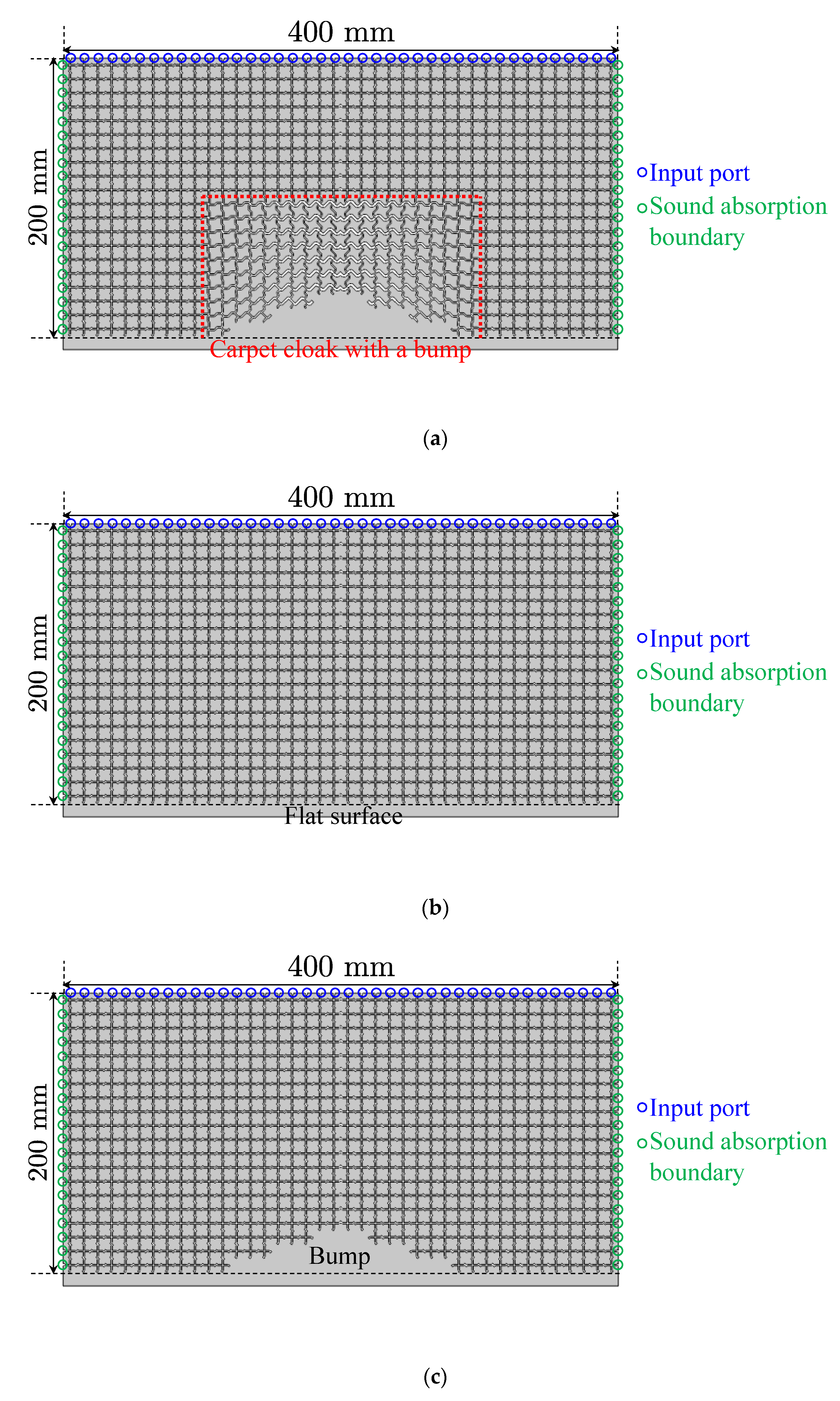
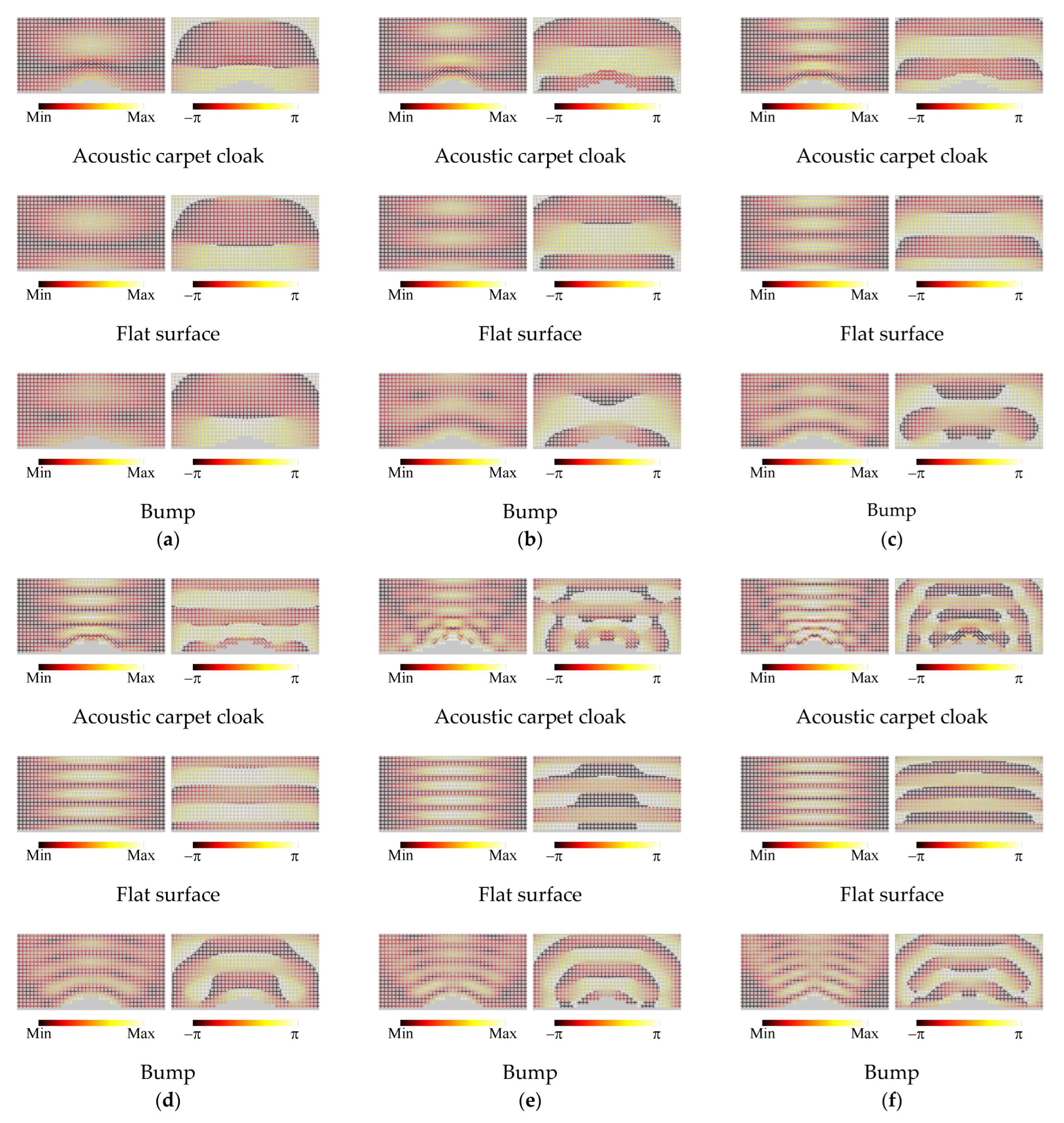
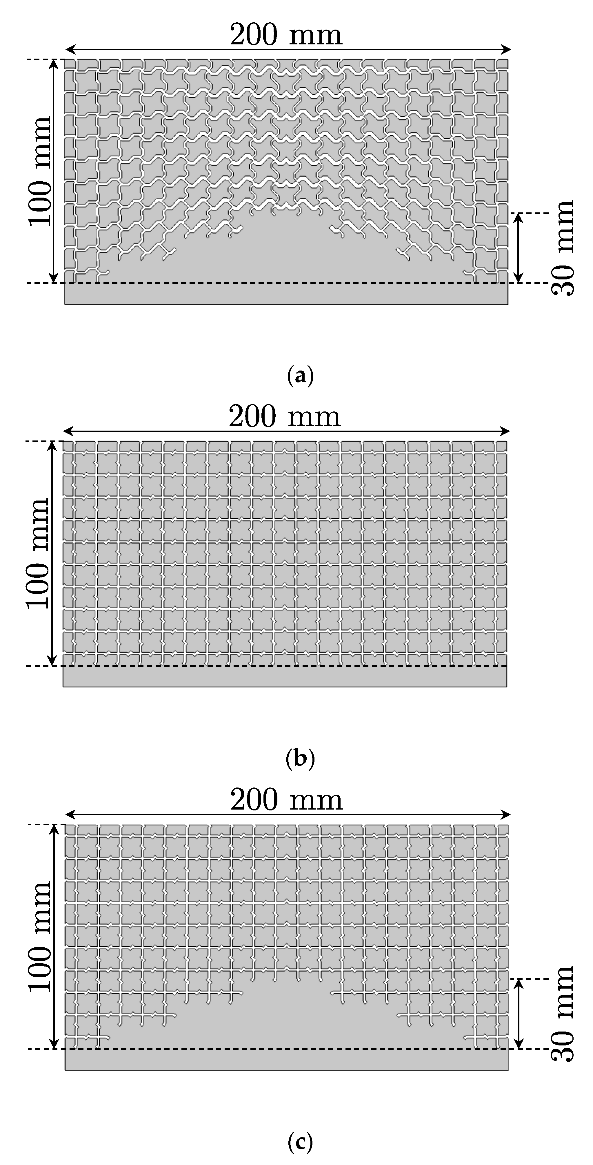
3.1. Acoustic Carpet Cloak

Figure 12a shows the setup for the full-wave simulations of the acoustic carpet cloak and the size of the analysis area is set to 400 mm × 200 mm. The designed carpet cloak in Figure 10a is arranged at the center of the bottom in that area, and the other area corresponds to the background medium constituted by using the structures of Figure 4. Forty input ports are connected to the waveguides of the upper boundary and a Gaussian beam with a beam waist of 100 mm is injected from there. Furthermore, the rigid body walls are set as the bottom boundary and other boundaries are selected as the absorption boundary. We calculated the complex sound pressure distributions in the waveguides by the Acoustics Module of COMSOL and compared the results with those for the cases with the flat floor in Figure 10b (see Figure 12b) and the bump in Figure 10c (see Figure 12c). Incidentally, the number of meshes in these simulations was approximately 1.4 million and the calculation time was approximately one hour.
The calculated results of the amplitude and phase distributions of the sound pressure are shown in Figure 13a–f, and the frequencies are set to 1.0, 1.5, 2.0, 2.5, 3.0, and 3.5 kHz, respectively. The values of the wavelength per unit cell length (λ/Δd) are 22.3, 14.8, 11.1, 8.91, 7.42, and 6.36. It is seen from the results of Figure 13a–d that the carpet cloak can sufficiently suppress the scattered waves by the bump and mimics the flat surface. On the other hand, the level of the scattered wave becomes large in the cases of Figure 13e,f. This reason is that the influence by the discretization error becomes large due to the shorter wavelength than in the other cases. Therefore, we can conclude from the results above that the designed acoustic carpet cloak can operate at least up to 2.5 kHz (λ/Δd = 8.91).

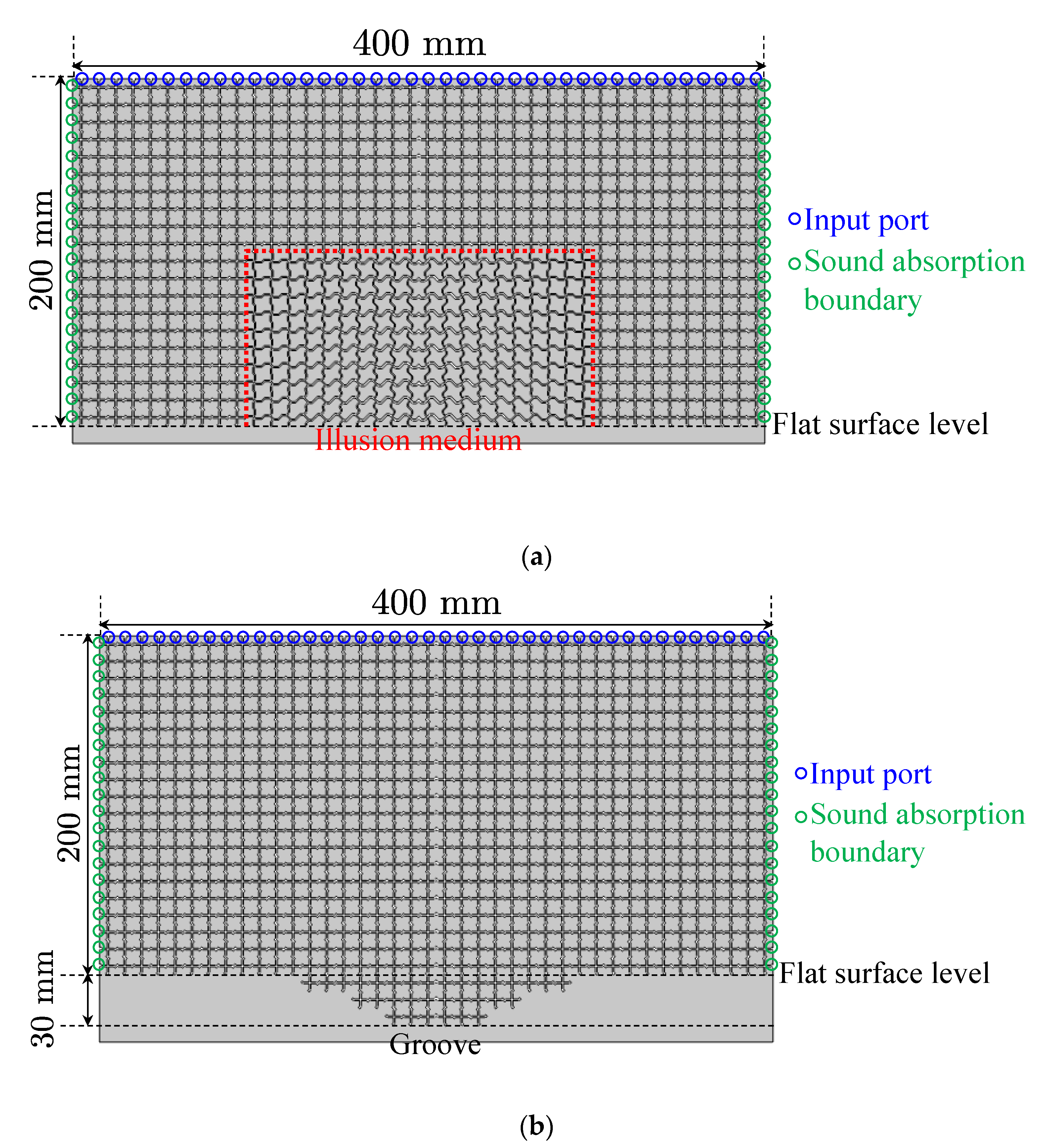
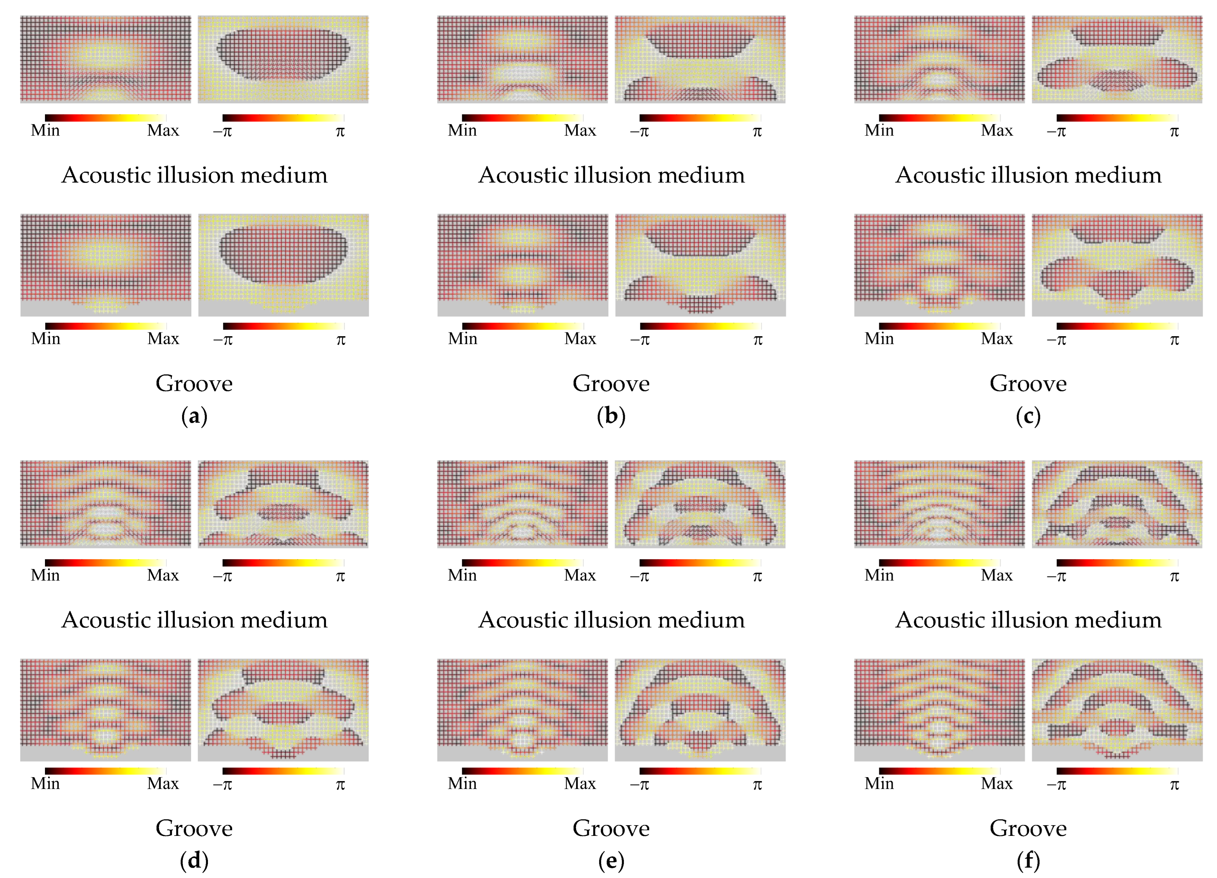
3.2. Acoustic Illusion Medium

The setup for the full-wave simulations of the acoustic illusion medium is shown in Figure 14a. The size of the analysis area, the input ports, and the boundary conditions are set to the same as those for the acoustic carpet cloak, and the designed illusion medium in Figure 11a is placed at the center of the bottom in that area. As is the case in Figure 13, we calculated the complex sound pressure distributions in the waveguides by the Acoustics Module of COMSOL and compared the results with those for the case with the groove in Figure 11b (see Figure 14b). Incidentally, the number of meshes and the calculation time were almost the same as in the acoustic carpet cloak case.
The calculated results of the amplitude and phase distributions of the sound pressure are shown in Figure 15a–f, and the frequencies are set to the same values as in the cases of Figure 13a–f, respectively. Differences of distributions in the background medium region between the acoustic illusion medium case and the groove case are slightly large in the cases of the higher frequencies from these results. However, it can be seen that the scattered waves from the groove are sufficiently mimicked by the acoustic illusion medium and the performance is better than that of the acoustic carpet cloak. The reason for this is considered to be that the area discretized by the unit cells is larger than that in the case of the acoustic carpet cloak and the influence of the discretization error is small. Therefore, it can be concluded from the results, and those of the acoustic carpet cloak, that the broadband operations and the validity of the proposed design method can be shown.

4. Conclusions

Firstly, the theory of 2-D distributed TL models for the full-tensor anisotropic electromagnetic metamaterials was introduced to acoustic metamaterials in order to theoretically design unit cell structures constituting broadband acoustic metamaterials based on the concept of transformation acoustics. The formulas of 2-D equivalent circuit models for full-tensor anisotropic acoustic metamaterials were recalled, and the design formulas of the TL models for electromagnetic metamaterials were updated to those for determining the structural parameters of unit cells of acoustic metamaterials.
Secondly, 2-D acoustic waveguide unit cell structures were proposed and the design formulas were shown to determine the waveguide widths and lengths according to the updated theory of the 2-D distributed TL models. To show the design examples and the usefulness, an acoustic carpet cloak and an illusion medium were designed with the proposed structures and those structural parameters were determined by using the design formulas theoretically.
Finally, full-wave simulations were carried out with the Acoustics Module of COMSOL and complex pressure distributions were calculated. The results show the broadband operations of the designed acoustic carpet cloak and the illusion medium, and it is concluded that the validity of the proposed method introduced from electromagnetic metamaterials has been demonstrated.

Author Contributions

Conceptualization, T.N. and A.T.; methodology, T.N.; validation, T.N. and A.T.; formal analysis, T.N. and A.T.; investigation, T.N. and A.T.; writing—original draft preparation, T.N.; writing—review and editing, T.N., S.F. and T.W.; project administration, T.N. All authors have read and agreed to the published version of the manuscript.

Funding

This work was funded by Supporting program for Young Researcher in Kagoshima University and JSPS KAKENHI Grant Number JP18K14132.

Data Availability Statement

Not applicable.

Acknowledgments

The authors would like to thank Shuntaro Uchida and Rina Maeda for their technical assistance in a part of the contents.

Conflicts of Interest

The authors declare no conflict of interest.

References

  1. Christopoulos, C. The Transmission-Line Modeling Method: TLM; IEEE: New York, NY, USA, 1995; pp. 51–100. [Google Scholar]
  2. Caloz, C.; Itoh, T. Application of the transmission line theory of left-handed (LH) materials to the realization of a microstrip LH transmission line. IEEE Antennas Propag. Soc. Int. Symp. 2002, 2, 412–415. [Google Scholar]
  3. Oliner, A.A. A periodic-structure negative-refractive-index medium without resonant elements. IEEE AP-S/URSI Int. Symp. Dig. 2002, 2002, 41. [Google Scholar]
  4. Eleftheriades, G.V.; Iyer, A.K.; Kremer, P.C. Planar negative refractive index media using periodically L–C loaded transmission lines. IEEE Trans. Microw. Theory Techn. 2002, 50, 2702–2712. [Google Scholar] [CrossRef]
  5. Sanada, A.; Caloz, C.; Itoh, T. Characteristics of the composite right/left-handed transmission lines. IEEE Microw. Wirel. Comp. Lett. 2004, 14, 68–70. [Google Scholar] [CrossRef]
  6. Sanada, A.; Caloz, C.; Itoh, T. Planar distributed structures with negative refractive index. IEEE Trans. Microw. Theory Tech. 2004, 52, 1252–1263. [Google Scholar] [CrossRef]
  7. Nagayama, T.; Sanada, A. Physical equivalent circuit model for 2D full-tensor anisotropic metamaterials. IEEE MTT-S Int. Microw. Symp. Dig. 2013, 1–3. [Google Scholar]
  8. Nagayama, T.; Sanada, A. Planar distributed full-tensor anisotropic metamaterials for transformation electromagnetics. IEEE Trans. Microw. Theory Techn. 2015, 63, 3851–3861. [Google Scholar] [CrossRef]
  9. Pendry, J.B.; Schurig, D.; Smith, D.R. Controlling electromagnetic fields. Science 2006, 312, 1780–1782. [Google Scholar] [CrossRef] [PubMed] [Green Version]
  10. Schurig, D.; Pendry, J.B.; Smith, D.R. Calculation of material properties and ray tracing in transformation media. Opt. Exp. 2006, 14, 9794–9804. [Google Scholar] [CrossRef]
  11. Schurig, D.; Mock, J.J.; Justice, B.J.; Cummer, S.A.; Pendry, J.B.; Starr, A.F.; Smith, D.R. Metamaterial electromagnetic cloak at microwave frequencies. Science 2006, 314, 977–980. [Google Scholar] [CrossRef] [PubMed] [Green Version]
  12. Alitalo, P.; Luukkonen, O.; Jylhä, L.; Venermo, J.; Tretyakov, S. Transmission-line networks cloaking objects from electromagnetic fields. IEEE Trans. Antennas Propagat. 2008, 56, 416–424. [Google Scholar] [CrossRef] [Green Version]
  13. Tretyakov, S.; Alitalo, P.; Luukkonen, O.; Simovski, C. Broadband electromagnetic cloaking of long cylindrical objects. Phys. Rev. Lett. 2009, 103, 103905. [Google Scholar] [CrossRef] [PubMed]
  14. Liu, X.; Li, C.; Yao, K.; Meng, X.; Feng, W.; Wu, B.; Li, F. Experimental verification of broadband invisibility using a cloak based on inductor-capacitor networks. Appl. Phys. Lett. 2009, 95, 191107. [Google Scholar] [CrossRef]
  15. Kanté, B.; Germain, D.; de Lustrac, A. Experimentaldemonstration of a nonmagnetic metamaterial cloak at microwave frequencies. Phys. Rev. B 2009, 80, 201104. [Google Scholar] [CrossRef] [Green Version]
  16. Alù, A. Mantle cloak: Invisibility induced by a surface. Phys. Rev. B 2009, 80, 245115. [Google Scholar] [CrossRef]
  17. Padooru, Y.R.; Yakovlev, A.B.; Chen, P.-Y.; Alù, A. Analytical modeling of conformal mantle cloaks for cylindrical objects using subwavelength printed and slotted arrays. Appl. Phys. Lett. 2012, 112, 034907. [Google Scholar]
  18. Selvanayagam, M.; Eleftheriades, G. An active electromagnetic cloak based on the equivalence principle. IEEE Antennas Microw. Wirel. Propag. Lett. 2012, 11, 10. [Google Scholar]
  19. Selvanayagam, M.; Eleftheriades, G. Experimental demonstration of active electromagnetic cloaking. Phys. Rev. X 2013, 3, 041011. [Google Scholar] [CrossRef] [Green Version]
  20. Schofield, R.S.; Soric, J.C.; Rainwater, D.; Kerkhoff, A.; Alù, A. Scattering suppression and wideband tenability of a flexible mantle cloak for finite-length conducting rods. New J. Phys. 2014, 16, 063063. [Google Scholar] [CrossRef]
  21. Sun, F.; Liu, Y.; He, S. Surface transformation multi-physics for controlling electromagnetic and acoustic waves simultaneously. Opt. Exp. 2020, 28, 94–106. [Google Scholar] [CrossRef]
  22. Zhen, Z.; Qian, C.; Jia, Y.; Fan, Z.; Hao, R.; Cai, T.; Zheng, B.; Chen, H.; Li, E. Realizing transmitted metasurface cloak by a tandem neural network. Photonics. Res. 2021, 9, B229. [Google Scholar] [CrossRef]
  23. Li, J.; Pendry, J.B. Hiding under the carpet: A new strategy for cloaking. Phys. Rev. Lett. 2008, 101, 203901. [Google Scholar] [CrossRef] [PubMed] [Green Version]
  24. Liu, R.; Ji, C.; Mock, J.J.; Chin, J.Y.; Cui, T.J.; Smith, D.R. Broadband ground-plane cloak. Science 2009, 323, 366–369. [Google Scholar] [CrossRef] [PubMed]
  25. Valentine, J.; Li, J.; Zentgraf, T.; Bartal, G.; Zhang, X. An optical cloak made of dielectrics. Nat. Mater. 2009, 8, 568–571. [Google Scholar] [CrossRef] [PubMed] [Green Version]
  26. Lee, J.H.; Blair, J.; Tamma, V.A.; Wu, Q.; Rhee, S.J.; Summers, C.J.; Park, W. Direct visualization of optical frequency invisibility cloak based on silicon nanorod array. Opt. Exp. 2009, 17, 12922–12928. [Google Scholar] [CrossRef]
  27. Gabrielli, L.H.; Cardenas, J.; Poitras, C.B.; Lipson, M. Silicon nanostructure cloak operating at optical frequencies. Nature Photon. 2009, 3, 461–463. [Google Scholar] [CrossRef] [Green Version]
  28. Ergin, T.; Stenger, N.; Brenner, P.; Pendry, J.B.; Wegener, M. Three-dimensional invisibility cloak at optical wavelengths. Science 2010, 328, 337–339. [Google Scholar] [CrossRef] [Green Version]
  29. Ma, H.F.; Cui, T.J. Three-dimensional broadband ground-plane cloak made of metamaterials. Nat. Commun. 2011, 1, 21. [Google Scholar] [CrossRef] [Green Version]
  30. Huang, Y.; Zhang, J.; Zhou, J.; Qiang, B.; Xu, Z.; Liu, L.; Tao, J.; Kossowski, N.; Wang, Q.; Luo, Y. Polarization-robust mid-infrared carpet cloak with minimized lateral shift. Photonics. Res. 2021, 9, 944. [Google Scholar] [CrossRef]
  31. Lai, Y.; Ng, J.; Chen, H.Y.; Han, D.Z.; Xiao, J.J.; Zhang, Z.Q.; Chan, C.T. Illusion Optics: The optical transformation of an object into another object. Phys. Rev. Lett. 2009, 102, 253902. [Google Scholar] [CrossRef] [Green Version]
  32. Nagayama, T.; Sanada, A. Broadband transmission-line illusions based on transformation electromagnetics. EPJ Appl. Metamat. 2019, 6, 23. [Google Scholar] [CrossRef] [Green Version]
  33. Nagayama, T.; Uchida, S.; Fukushima, S.; Watanabe, T. Equivalent Circuit models for two-dimensional full-tensor anisotropic acoustic metamaterials. In Proceedings of the 2019 Photonics and Electromagnetics Research Symposium-Fall (PIERS-Fall), Xiamen, China, 17–20 December 2019; pp. 989–995. [Google Scholar]
  34. Toshima, A.; Nagayama, T.; Fukushima, S.; Watanabe, T. Acoustic illusion medium mimicking scattered waves of a groove on a flat surface based on transformation acoustics. In Proceedings of the 2021 Photonics and Electromagnetics Research Symposium (PIERS), Hangzhou, China, 21–25 November 2021; pp. 2587–2592. [Google Scholar]
  35. Cummer, S.A.; Schurig, D. One path to acoustic cloaking. New J. Phys. 2007, 9, 45. [Google Scholar] [CrossRef]
  36. Chen, H.; Chan, C.T. Acoustic cloaking in three dimensions using acoustic metamaterials. Appl. Phys. Lett. 2007, 91, 183518. [Google Scholar] [CrossRef]
  37. Norris, A.N. Acoustic cloaking theory. Proc. R. Soc. A Math. Phys. Eng. Sci. 2008, 464, 2411–2434. [Google Scholar] [CrossRef]
  38. Torrent, D.; Sánchez-Dehesa, J. Acoustic cloaking in two dimensions: A feasible approach. New J. Phys. 2008, 10, 063015. [Google Scholar] [CrossRef]
  39. Zhang, S.; Xia, C.; Fang, N. Broadband acoustic cloak for ultrasound waves. Phys. Rev. Lett. 2011, 106, 024301. [Google Scholar] [CrossRef]
  40. García-Chocano, V.M.; Sanchis, L.; Díaz-Rubio, A.; Martínez-Pastor, J.; Cervera, F.; Llopis-Pontiveros, R.; Sánchez-Dehesa, J. Acoustic cloak for airborne sound by inverse design. Appl. Phys. Lett. 2011, 99, 074102. [Google Scholar] [CrossRef]
  41. Guild, M.D.; Haberman, M.R.; Alù, A. Plasmonic-type acoustic cloak made of a bilaminate shell. Phys. Rev. B 2012, 86, 104302. [Google Scholar] [CrossRef]
  42. Jo, C.; Jeong, J.; Kwon, B.-J.; Park, K.-C.; Oh, I.-K. Omnidirectional two-dimensional acoustic cloak by axisymmetric cylindrical lattices. Wave Motion 2015, 54, 157–169. [Google Scholar] [CrossRef]
  43. Farhat, M.; Guenneau, S.; Alù, A.; Wu, Y. Scattering cancellation technique for acoustic spinning objects. Phys. Rev. B 2020, 101, 174111. [Google Scholar] [CrossRef]
  44. Lin, C.; Liu, D.; Eggler, D.; Kessissoglou, N. Active acoustic cloaking and illusions of sound-hard bodies using the boundary element method. J. Acoust. Soc. Am. 2021, 149, 1803–1812. [Google Scholar] [CrossRef] [PubMed]
  45. Ahmed, W.W.; Farhat, M.; Zhang, X.; Wu, Y. Deterministic and probabilistic deep learning models for inverse design of broadband acoustic cloak. Phys. Rev. Res. 2021, 3, 013142. [Google Scholar] [CrossRef]
  46. Fujii, G.; Takahashi, M.; Akimoto, Y. Acoustic cloak designed by topology optimization for acoustic–elastic coupled systems. Appl. Phys. Lett. 2021, 118, 101102. [Google Scholar] [CrossRef]
  47. Matsushima, K.; Noguchi, Y.; Yamada, T. Omnidirectional acoustic cloaking against airborne sound realized by a locally resonant sonic material. Sci. Rep. 2022, 12, 16383. [Google Scholar] [CrossRef]
  48. Popa, B.-I.; Zigoneanu, L.; Cummer, S.A. Experimental acoustic ground cloak in air. Phys. Rev. Lett. 2011, 106, 253901. [Google Scholar] [CrossRef]
  49. Popa, B.-I.; Cummer, S.A. Homogeneous and compact acoustic ground cloaks. Phys. Rev. B 2011, 83, 224304. [Google Scholar] [CrossRef] [Green Version]
  50. Zigoneanu, L.; Popa, B.-I.; Cummer, S.A. Three-dimensional broadband omnidirectional acoustic ground cloak. Nat. Mater. 2014, 13, 352–355. [Google Scholar] [CrossRef] [Green Version]
  51. Bi, Y.; Lu, W.; Ji, P.; Yang, J. Design and demonstration of an underwater acoustic carper cloak. Sci. Rep. 2017, 7, 705. [Google Scholar] [CrossRef] [Green Version]
  52. Chen, J.; Liu, J. Broadband underwater acoustic carpet cloak based on pentamode materials under normal incidence. AIP Adv. 2018, 8, 085024. [Google Scholar] [CrossRef]
  53. Guo, J.; Zhou, J. An ultrathin acoustic carpet cloak based on resonators with extended necks. J. Phys. D Appl. Phys. 2020, 53, 505501. [Google Scholar] [CrossRef]
  54. Xue, Y.; Zhang, X. Self-adaptive acoustic cloak enabled by soft mechanical metamaterials. Extrem. Mech. Lett. 2021, 46, 101347. [Google Scholar] [CrossRef]
  55. Eslamzadeh, S.; Ghaffari-Miab, M.; Abbasi-Arand, B. Design of a broadband metamaterial-based acoustic lens using elaborated carpet cloak strategy. Appl. Phys. A 2021, 127, 897. [Google Scholar] [CrossRef]
  56. Zhou, P.; Jia, H.; Bi, Y.; Liao, B.; Yang, Y.; Yan, Y.; Yan, K.; Zhang, J.; Yang, J. Underwater Carpet Cloak for Broadband and Wide-Angle Acoustic Camouflage Based on Three-Component Metafluid. Phys. Rev. Appl. 2022, 18, 014050. [Google Scholar] [CrossRef]
  57. Kan, W.; Liang, B.; Zhu, X.; Li, R.; Zou, X.; Wu, H.; Yang, J.; Cheng, J. Acoustic illusion near boundaries of arbitrary curved geometry. Sci. Rep. 2013, 3, 1427. [Google Scholar] [CrossRef] [PubMed] [Green Version]
  58. Kan, W.; Liang, B.; Ji, R.; Jiang, X.; Zou, Z.; Yin, L.-I.; Cheng, J. Three-dimensional broadband acoustic illusion cloak for sound-hard boundaries of curved geometry. Sci. Rep. 2016, 6, 36936. [Google Scholar] [CrossRef]
  59. Eggler, D.; Kessissoglou, N. Active structural acoustic illusions. Sci. Rep. 2020, 10, 9772. [Google Scholar] [CrossRef]
  60. Hu, C.; Yin, Y.; Chen, H. Three-Dimensional Omnidirectional Acoustic Illusion. Phys. Rev. Appl. 2022, 18, 024049. [Google Scholar] [CrossRef]
Figure 1. 2-D equivalent circuit models for full-tensor anisotropic acoustic metamaterials. (a) ρxx < 0 case; (b) ρxx > 0 case.
Crystals 12 01557 g001
Figure 2. 2-D distributed TL models for determining the structural parameters of unit cells of full-tensor anisotropic acoustic metamaterials to be introduced from electromagnetic metamaterials. (a) ρxx < 0 case; (b) ρxx > 0 case. In the case of acoustic metamaterials, the phase constants (β and βM) of TLs correspond to those of acoustic waves.
Crystals 12 01557 g002
Figure 3. 2-D acoustic waveguide unit cell structures for realizing full-tensor anisotropic acoustic metamaterials. (a) ρxx < 0 case; (b) ρxx > 0 case. The waveguides are formed in the rigid body and are filled with the air.
Crystals 12 01557 g003
Figure 4. 2-D acoustic waveguide unit cell structures for the background medium. (a) For connecting to Figure 3a; (b) for connecting to Figure 3b. The waveguides are formed in the rigid body and are filled with the air.
Crystals 12 01557 g004
Figure 5. 2-D distributed TL model for the background medium.
Crystals 12 01557 g005
Figure 6. Concept of an acoustic carpet cloak. (a) Original coordinate system on a flat surface and the reflection from the flat surface; (b) transformed coordinate system on a bump and the reflection from an acoustic carpet cloak covering the bump. The same reflected wave as that from the flat surface is generated by controlling the trajectory of the incident acoustic wave, with the carpet cloak mimicking the transformed coordinate system and it looks as if there is not the bump on the flat surface.
Crystals 12 01557 g006
Figure 7. Concept of an illusion medium. (a) Original coordinate system on a groove and scatterings of the incident acoustic wave by the groove; (b) transformed coordinate system on a flat surface and scatterings of the incident acoustic wave from an illusion medium on the flat surface. The same scattered waves as that from the groove are generated by controlling the trajectory of the incident acoustic wave with the illusion medium and it looks like as if there is the groove on the flat surface.
Crystals 12 01557 g007
Figure 8. Calculated results of the waveguide widths and lengths for the acoustic carpet cloak (wM = 0.943 mm). (a) wx; (b) wy; (c) l; (d) lM.
Crystals 12 01557 g008
Figure 9. Calculated results of the waveguide widths and lengths for the acoustic illusion medium (wM = 0.667 mm). (a) wx; (b) wy; (c) l; (d) lM.
Crystals 12 01557 g009
Figure 10. Designed acoustic carpet cloak and the additional designed structures for comparison. (a) Carpet cloak; (b) flat surface; (c) bump. These sizes are 2p × h = 200 mm × 100 mm (2p × h) and those are discretized by using unit cells of Figure 3 (carpet cloak case) and Figure 4 (flat surface and bump cases) whose sizes are Δd × Δd = Δdb × Δdb = 10 mm × 10 mm. The structural parameters of Figure 8 are adopted to the unit cells of the carpet cloak, and those for the flat surface and the bump are wb = 1.0 mm and lb = 11 mm.
Crystals 12 01557 g010
Figure 11. Designed acoustic illusion medium and the additional designed structure for comparison. (a) Illusion medium; (b) groove. These sizes are 2p × h = 200 mm × 100 mm (2p × h) and those are discretized by using unit cells of Figure 3 (illusion medium case) and Figure 4 (groove case) whose sizes are Δd × Δd = Δdb × Δdb = 10 mm × 10 mm. Structural parameters of Figure 9 are adopted to the unit cells of the carpet cloak, and those for the groove are wb = 1.0 mm and lb = 11 mm.
Crystals 12 01557 g011
Figure 12. Full-wave simulation setup. (a) Acoustic carpet cloak; (b) flat surface; (c) bump. The designed structures in Figure 10a-c are placed at the center of the bottom of the background medium area (400 mm × 200 mm). The bottom boundaries are set as the rigid body walls.
Crystals 12 01557 g012
Figure 13. Complex sound pressure distributions for the acoustic carpet cloak, the flat surface, and the bump. (a) 1.0 kHz (λ/∆d = 22.3); (b) 1.5 kHz (λ/∆d = 14.8); (c) 2.0 kHz (λ/∆d = 11.1); (d) 2.5 kHz (λ/∆d = 8.91); (e) 3.0 kHz (λ/∆d = 7.42); (f) 3.5 kHz (λ/∆d = 6.36). Left: Amplitude. Right: Phase.
Crystals 12 01557 g013
Figure 14. Full-wave simulation setup. (a) Acoustic illusion medium; (b) groove. The designed structures in Figure 11a,b are placed at the center of the bottom of the background medium area (400 mm × 200 mm). In the case of (b), the groove is on the lower position than the flat surface level. The bottom boundaries are set as the rigid body walls.
Crystals 12 01557 g014
Figure 15. Complex sound pressure distributions for the acoustic illusion medium and the groove. (a) 1.0 kHz (λ/∆d = 22.3); (b) 1.5 kHz (λ/∆d = 14.8); (c) 2.0 kHz (λ/∆d = 11.1); (d) 2.5 kHz (λ/∆d = 8.91); (e) 3.0 kHz (λ/∆d = 7.42); (f) 3.5 kHz (λ/∆d = 6.36). Left: Amplitude. Right: Phase.
Crystals 12 01557 g015
Table 1. Circuit equations, 2-D Maxwell’s equations, and 2-D acoustic equations for full-tensor anisotropic electromagnetic or acoustic metamaterials.
Circuit Equations2-D Maxwell’s Equations2-D Acoustic Equations
I x + 1 I x Δ d I y + 1 I y Δ d = j ω C V c H y x H x y = j ω ε z E z v x x v y y = j ω 1 K p
V x + 1 V x Δ d = ± j ω M I y + 1 + I y 2 j ω L x I x + 1 + I x 2 E z x = j ω μ y x H x + j ω μ y y H y p x = j ω ρ x y v y j ω ρ x x v x
V y + 1 V y Δ d = j ω L y I y + 1 + I y 2 ± j ω M I x + 1 + I x 2 E z y = j ω μ x x H x j ω μ x y H y p y = j ω ρ y y v y j ω ρ y x v x
Table 2. Correspondences of voltages, currents, electric fields, magnetic fields, scalar pressures, and fluid velocities in the equations of Table 1.
Circuit Equations2-D Maxwell’s Equations2-D Acoustic Equations
V c E z p
V x + 1 V x Δ d E z x p x
V y + 1 V y Δ d E z y p y
I x + 1 + I x 2 H y v x
I y + 1 + I y 2 H x v y
I x + 1 I x Δ d H y x v x x
I y + 1 I y Δ d H x y v y y
Publisher’s Note: MDPI stays neutral with regard to jurisdictional claims in published maps and institutional affiliations.

