Article

Recovery of Scandium, Aluminum, Titanium, and Silicon from Iron-Depleted Bauxite Residue into Valuable Products: A Case Study

1
A.A. Baikov Institute of Metallurgy and Materials Science, Russian Academy of Science, 49 Leninsky Prosp., 119334 Moscow, Russia
2
Institute of Solid State Chemistry, Ural Branch of the Russian Academy of Sciences, 91 Pervomaiskaya St., 620990 Ekaterinburg, Russia
3
Faculty of Biotechnology and Industrial Ecology, D. Mendeleev University of Chemical Technology of Russia, 9 Miusskaya Square, 125047 Moscow, Russia
*
Authors to whom correspondence should be addressed.
Crystals 2022, 12(11), 1578; https://doi.org/10.3390/cryst12111578
Submission received: 6 October 2022 / Revised: 31 October 2022 / Accepted: 3 November 2022 / Published: 5 November 2022
(This article belongs to the Special Issue Extractive Metallurgy and Chemistry)

Abstract

:
Bauxite residue is a high-iron waste of the alumina industry with significant contents of scandium, aluminum, and titanium. This study focuses on the recovery of Sc, Al, Ti, and Si from iron-depleted bauxite residue (IDBR) into valuable products. Iron depletion was carried out using reduction roasting followed by low-intensity magnetic separation to enrich bauxite residue in Al, Ti, and Sc and reduce an adverse effect of iron on scandium extraction. Hydrochloric high-pressure acid leaching, aluminum precipitation by saturation of the acid leachate, solvent extraction of scandium using di(2-ethylhexyl) phosphoric acid (HDEHP) and tributyl phosphate (TBP), alkaline leaching of the acid residue with subsequent silica precipitation were used to obtain appropriate selective concentrates. As a result, scandium concentrate of 94% Sc2O3, crude alumina of 93% Al2O3, titanium concentrate of 41.5% TiO2, and white carbon of 77% SiO2 were prepared and characterized. Based on the characterization of the treatment stages and the obtained valuable products, the prospect for the application of the suggested flowsheet was discussed.

1. Introduction

Due to the global depletion of natural resources and a decrease in ore grade [1], the recovery of valuable metals from industrial wastes is increasingly attractive. In recent years, the demand for rare-earth metals has increased significantly [2], among which scandium is a scattered element with unique properties. It is estimated [3] that a considerable increase in the global scandium market should be expected in the next decade. It can facilitate the development of technologies for processing not only natural resources but also industrial wastes containing scandium. One of the well-known high-scandium industrial wastes generated and accumulated in huge amounts is bauxite residue from alumina production by the Bayer process, which is also known as red mud [4]. The scandium content in the bauxite residue is much higher than its content both in primary sources and industrial wastes, e.g., fly ash or phosphogypsum [5]. The production of 1 ton of alumina generates up to 1.5 tons of bauxite residue [6,7]. According to known data, the global accumulation of bauxite residue increases by 150 million tons per year [8] and has already exceeded 5 billion tons in 2020 [9]. It has high pH values (pH > 11) [10], as well as high dispersiveness [11] due to its generation through the alkali treatment by the Bayer method [12]. The bauxite residue is stored in special disposal areas and poses environmental risks [13]. The storage causes groundwater pollution [14], risks of air dispersion [15], and surface water pollution [16], as well as significant costs [17]. In recent years, dam failures in disposal areas led to environmental disasters in Hungary [18] and China [19] in 2010 and 2016, respectively. Recycling of bauxite residue is necessary to decrease the bauxite residue amount, thereby reducing the risk of such accidents.
Currently, a small percentage of bauxite residue is recycled in the construction industry [20], but it leads to the loss of valuable elements. It should be noted that besides a significant scandium content, bauxite residue has high contents of major elements, such as iron, aluminum, and titanium, which depends on the chemical and mineralogical composition of the original bauxite, as well as on the conditions of its processing [21].
Comprehensive recovery of all valuable components from bauxite residue is a currently important task for researchers, but technological hindrances and lack of economic viability disallow the use of developed processes on an industrial scale [22]. It is reported that similar to the conventional Bayer process, the alkaline hydrothermal process using divalent iron ions has been successfully applied to extract only alumina, as well as enrich and partly magnetize iron-containing residue [23,24]. To recover more valuable components from bauxite residue, the methods based on leaching by inorganic acids with subsequent extraction of valuable elements from the leached solutions are widespread [25,26]. In particular, it is known about obtaining pure compounds from bauxite residues, such as TiO2 [27], which is used as a pigment in the production of paintwork materials, and Sc2O3, which is used in the production of high-temperature ceramics [28]. One of the main disadvantages of the acid leaching methods application for high-silica materials at room temperature is the formation of silica gel, which causes problems with filtration [29]. An effective way to avoid the formation of silica gel during leaching is the application of pressure acid leaching [30]. Among a variety of methods, hydrochloric acid leaching followed by selective recovery of scandium by solvent extraction methods [31,32] is proved to be efficient. A variety of acidic and neutral organophosphorus extractants such as di(2-ethylhexyl) phosphoric acid (HDEHP), tributyl phosphate (TBP), trioctylphosphine oxide (TOPO), Cyanex have been reported to be suitable for Sc separation from aqueous solutions [32,33,34]. Because of the higher extraction efficiency of the combined reagents, the solvent extraction procedures have proved to be more effective, which led to high enrichment of metal ions from their trace content in the initial solution [26,35,36,37,38]. Di(2-ethylhexyl) phosphoric acid (HDEHP) modified by tributylphosphate (TBP) has shown to be a promising organic solvent due to high extraction degree Sc, Y, and other rare-earth elements (REEs) [39,40,41,42]. However, these extractants also cause a significant co-extraction of iron [43], so iron removal treatment is recommended for the appropriate application of such a method. Accordingly, in our previous paper [44], we thoroughly studied the behavior of valuable elements during high-pressure hydrochloric acid leaching of iron-depleted bauxite residue (IDBR), which was obtained by carbothermic roasting of original bauxite residue followed by magnetic separation of iron. Figure 1 illustrates a conceptual flowsheet of the bauxite residue treatment in previous and present studies.
In this work, we focus on the recovery of valuable elements such as scandium, aluminum, titanium, and silicon by various methods from the solution and the solid residue of high-pressure hydrochloric acid leaching obtained from IDBR to obtain valuable products. In particular, we have attempted to precipitate alumina from the leached solution by its saturation by hydrochloric acid vapor, then to extract scandium by the method based on solvent extraction using HDEHP and TBP. In addition, we have tried to prepare amorphous silica and titanium concentrate from the solid leaching residue by alkaline leaching. Based on the characterization of the flowsheet stages and the obtained valuable products, the prospects for the application of the proposed approaches were elucidated.

2. Materials and Methods

2.1. Raw Materials

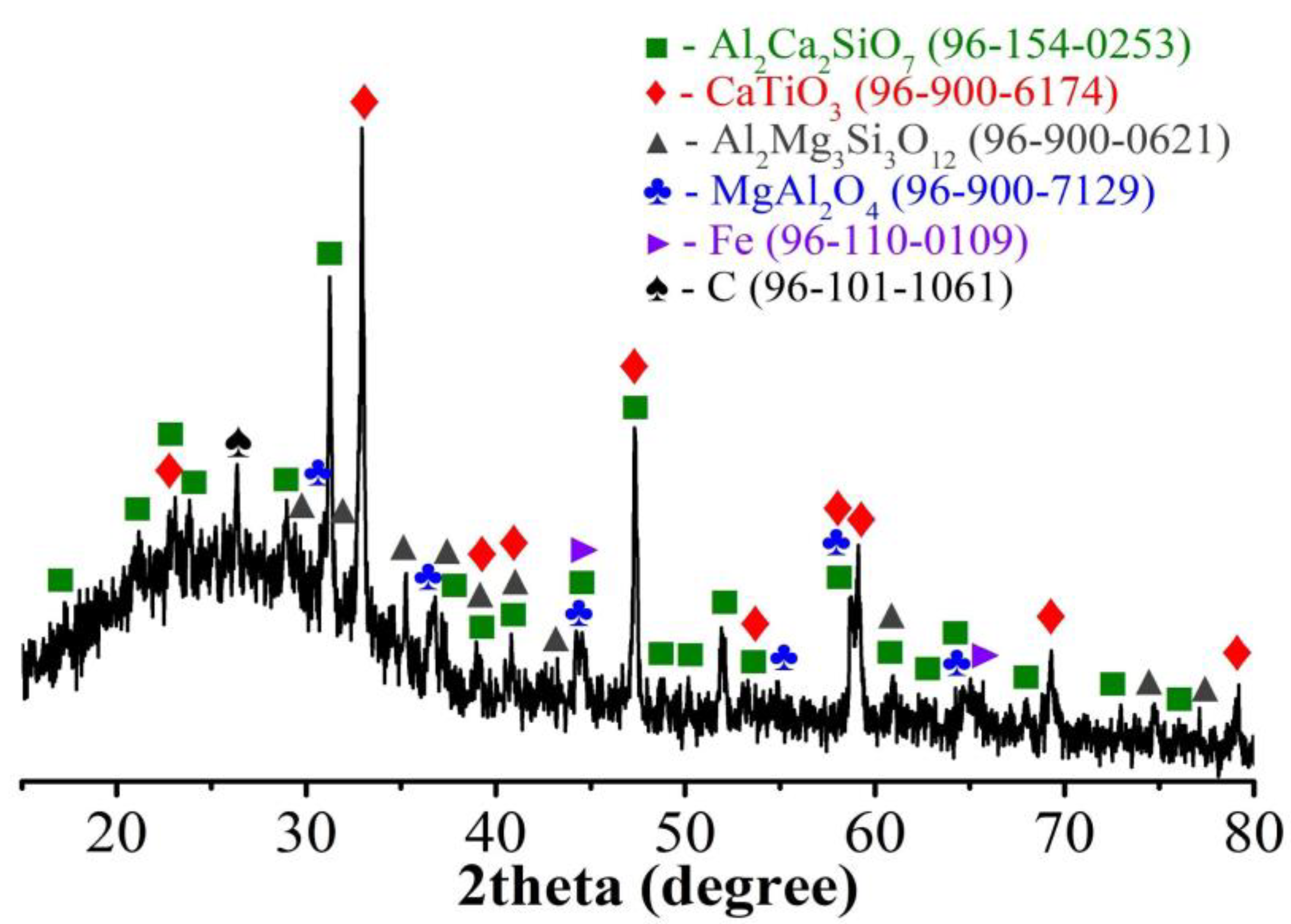
Table 1 shows the elemental composition of the original bauxite residue sample brought from the Bogoslovsky aluminum plant (Krasnoturyinsk, Sverdlovsk region, Russia) and the iron-depleted bauxite residue (IDBR) sample. Figure 2 demonstrates the XRD pattern of the IDBR sample. Iron depletion of the sample was carried out by carbothermic reduction roasting of bauxite residue at 1300 °C for 60 min, followed by low-intensity magnetic separation using a magnetic field of 0.1 T. A detailed description of the iron depletion process is presented in [45].
According to Table 1, the IDBR sample prepared using carbothermic roasting contains 4.3% Fe, while 34.8% Fe is in the original bauxite residue sample, and Ti, Al, and Sc contents are significantly increased in the IDBR sample. Therefore, the treatment by HCl leaching is more suitable for it. As can be seen from the XRD pattern of the IDBR sample, aluminum is distributed between gehlenite (Al2Ca2SiO7), pyrope (Al2Mg3Si3O12), and magnesium aluminate (MgAl2O4); titanium was found in the perovskite (CaTiO3) form.
The IDBR sample was ground and sieved through a 300-mesh screen, then dried at 105 °C for 120 min in an air furnace. Other chemical reagents were purchased from JSC LenReactiv (Saint Petersburg, Russia) and Sigma Tek LLC (Khimki, Moscow region, Russia). The required solutions were prepared by dilution in distilled water.

2.2. Experiments

2.2.1. High-Pressure Hydrochloric Acid Leaching of IDBR

Hydrochloric acid leaching was performed using a laboratory-scale leaching autoclave P2004 (China). To investigate the influence of leaching temperature and time, 1 g of the IDBR sample and the 10% HCl acid at the liquid-to-solid (L/S) ratio of 11/1, which was defined as optimal previously [44], as well as a stirring bar, were placed in a 25 mL Teflon high-pressure vessel. This vessel was inserted in the stainless-steel pot; further, the pot was placed in the autoclave oven, then the heating and stirring at a speed of 350 rpm were powered on. The heating up to the required temperature was carried out over 20–25 min, then holding in the range from 0 to 30 min at 150, 170, 190, and 210 °C was performed. After cooling down, a mother liquor and a solid leaching residue were obtained by vacuum filtration. The residue was rinsed with distilled water and dried at 105 °C in an air furnace for 120 min.
The recovery degree of elements after the acid leaching was calculated by the following equation:
%ω = [1 − (msr∙%Esr)/(m0∙%E0)]∙100,
where %ω—element recovery degree, %; msr—mass of the solid residue, g; m0—mass of the IDBR sample, g; %E0 and %Esr—content of an element in the used IDBR sample and in the solid residue, respectively, %.
Then 30 g of the IDBR sample was leached at optimal conditions to obtain enough mother liquor and an acid leaching residue. As a result, 14 g of the acid residue and 220 mL of the mother liquor were produced for subsequent experiments.

2.2.2. Alumina Precipitation

Aluminum chloride hexahydrate (ACH) was precipitated from the mother liquor of the IDBR, leaching by its saturation by HCl vapor and cooling down; then, ACH was calcined to obtain Al2O3.
A gaseous mixture containing HCl and Ar was prepared to saturate the liquor. Hydrochloric acid of 36% was boiled in a conical flask of 500 mL on the heating plate, while Ar was supplied from a gas tank with a flow rate of 0.5 L/min. The mother liquor of 100 mL in a Drexel flask was placed in a beaker with a jacketed wall to maintain the chilled temperature of the solution at 10 °C. A gaseous mixture was blown into the liquor for 30 min; ACH precipitation was observed visually in the Drexel flask. Waste gases were neutralized in a flask with a sodium hydroxide solution. The resulting solution was filtered using a Schott funnel and washed with acetone to obtain ACH, saturated mother liquor, and washings. Then ACH was dried in an air furnace at 105 °C for 120 min. ACH was calcined to obtain Al2O3 in a porcelain crucible in a muffle furnace in the air at 800 °C for 60 min. To remove co-precipitated NaCl from the prepared Al2O3, washing with distilled water at room temperature for 15 min was used.

2.2.3. Scandium Solvent Extraction

Table 2 describes in detail the conditions of scandium extraction experiments.
To obtain an aqueous phase, the saturated solution remaining after ACH precipitation was diluted to 1 M HCl by distilled water to optimize acidity for scandium recovery and to prevent the formation of hardly stratifiable emulsion [46]. Taking into account the low scandium content in the diluted solution, we added a certain amount of the water solution with 0.77 g/L Sc3+ content intentionally in the aqueous phase to improve the sensitivity of its chemical analysis at the following stages. In order to decrease the co-extraction of Fe3+ with Sc3+, the solution was preliminarily treated with carbonyl iron to reduce Fe3+ to Fe2+. Hydrogen peroxide was used for conversion (TiO)2+ into [TiO(H2O2)]2+, which is poorly soluble in the organic phase, to prevent the co-extraction of titanium [47,48].
Previously, the organic phase, which consists of 10% di(2-ethylhexyl) phosphoric acid (HDEHP) as an extractant, 2% tributyl phosphate (TBP) as a modifier, and 80% kerosene as a solvent, was treated for 10 min by H2SO4 or HCl in a separatory funnel to purify the extractant from monomers and the solvent from unsaturated hydrocarbons with the removal of soluble aromatic sulfonic acids.
The extraction experiments were performed by mixing the aqueous phase, the organic phase, and 3% H2O2 solution in an organic-to-aqueous phase ratio (O/A) of 1/3 for 10 min. As a result, a raffinate and a loaded organic phase were prepared using a separatory funnel. The loaded organic phase was washed with HCl for 10 min and then rinsed with water for 10 min. In stripping experiments, the aqueous phase was separated from the organic phase using a separatory funnel in stand-by for 10 min. Then the aqueous solution with the Sc-containing precipitate was removed from the funnel (Exp. 1–2), or only the Sc-containing precipitate was filtered to remove the organic solution (Exp. 3). Sc2O3-based product was obtained using consecutive stages of dissolution and precipitation using various reagents indicated in Table 2, as well as calcination. An inductively-coupled plasma mass spectrometry method (ICP-MS) was used to determine the concentration of elements in the obtained solutions, and calcined scandium concentrates.
The distribution of the metallic ions between strip product, washing acid and raffinate was characterized by the recovery degree (ε), which was calculated as follows:
%ε = E/E0 × 100,
where E0 and E—the amount of elements in the initial solution and in the corresponding obtained phase (strip product, washing acid, and raffinate), respectively.

2.2.4. Preparation of Amorphous Silica and Titanium Concentrate

Alkaline leaching of silicon from the solid residue of high-pressure hydrochloric acid leaching of the IDBR sample was carried out as follows: 4 g of the residue was mixed with 48 mL of 5 M NaOH solution in a 100 mL beaker and heated up to 85 °C using a magnetic stirrer with an agitation speed of 500 rpm and holding time of 90 min. The hot solution was filtered with a vacuum using a Buchner funnel and two cone flasks to obtain a residue rich in titanium, sodium silicate liquor, and washings. The residue from the alkaline leaching was dried at 105 °C for 60 min.
The precipitation of silicon dioxide was carried out by adjusting the pH of the sodium silicate liquor. Firstly, it was heated up to 85 °C. Then 20% HCl was added dropwise into the solution, which was continuously agitated at 500 rpm to reach pH = 8.5 and gradually precipitate hydrated silica. Then the solution was aged for 30 min and filtered with a vacuum. Afterward, the precipitate was dried in an air furnace at 105 °C for 60 min. Then it was calcined at 250 °C for 60 min.

2.3. Analysis Methods

The chemical composition of the multicomponent solutions and washing waters, as well as the content of the main elements (Sc, Al, Ti, Fe) of solids (the IDBR sample, the leaching residues, and concentrates) after appropriate digestion, was determined using inductively coupled plasma mass spectrometry and inductively coupled plasma atomic emission spectrometry (ICP-AES) using Perkin Elmer ELAN 9000 (Waltham, MA, USA) and Agilent 725 (Mulgrave, Victoria, Australia) devices, respectively. The digestion was carried out using a mixture of concentrated H2SO4, HNO3, and HF. The calibration solutions and all samples were prepared by dilution with 2 wt.% HNO3. The total carbon and sulfur contents were measured using a Metavak CS-30 (Izhevsk, Russia) analyzer. The remaining elements were analyzed by X-ray fluorescence spectrometer AXIOSmax Advanced (Almelo, Netherlands) using fixed contents of Sc, Al, Ti, Fe, C, and S measured by the above-mentioned methods. The X-ray diffraction (XRD) patterns were collected by Shimadzu XRD-7000 (Kyoto, Japan) diffractometer using Cu Kα radiation in the 2θ angle range of 5–80° with a step of 0.03° and acquisition time of 2–5 s. Match! 3.12 software [49], as well as COD [50] and ICDD PDF [51] databases, were used for phase identification. The behavior of the samples during heating in the air was studied by simultaneous thermogravimetric and differential thermal analyses (TG–DTA) by Setaram Setsys Evolution 18 (Lyon, France) device using a heating rate of 10 K min−1. The prepared samples of the valuable products were investigated by a scanning electron microscopy method using JSM JEOL 6390LA (Tokyo, Japan) device equipped with an energy-dispersive X-ray (EDX) detector JEOL JED-2300. The specific surface area of the prepared white carbon and alumina was determined by the Brunauer–Emmett–Teller (BET) method using Micromeritics Gemini VII 2390 (Norcross, GA, USA) device. Isothermal drying and calcination of the solids were performed using a Nabertherm L9/12 (Lilienthal, Germany) muffle furnace.

3. Results

3.1. High-Pressure Hydrochloric Acid Leaching of IDBR

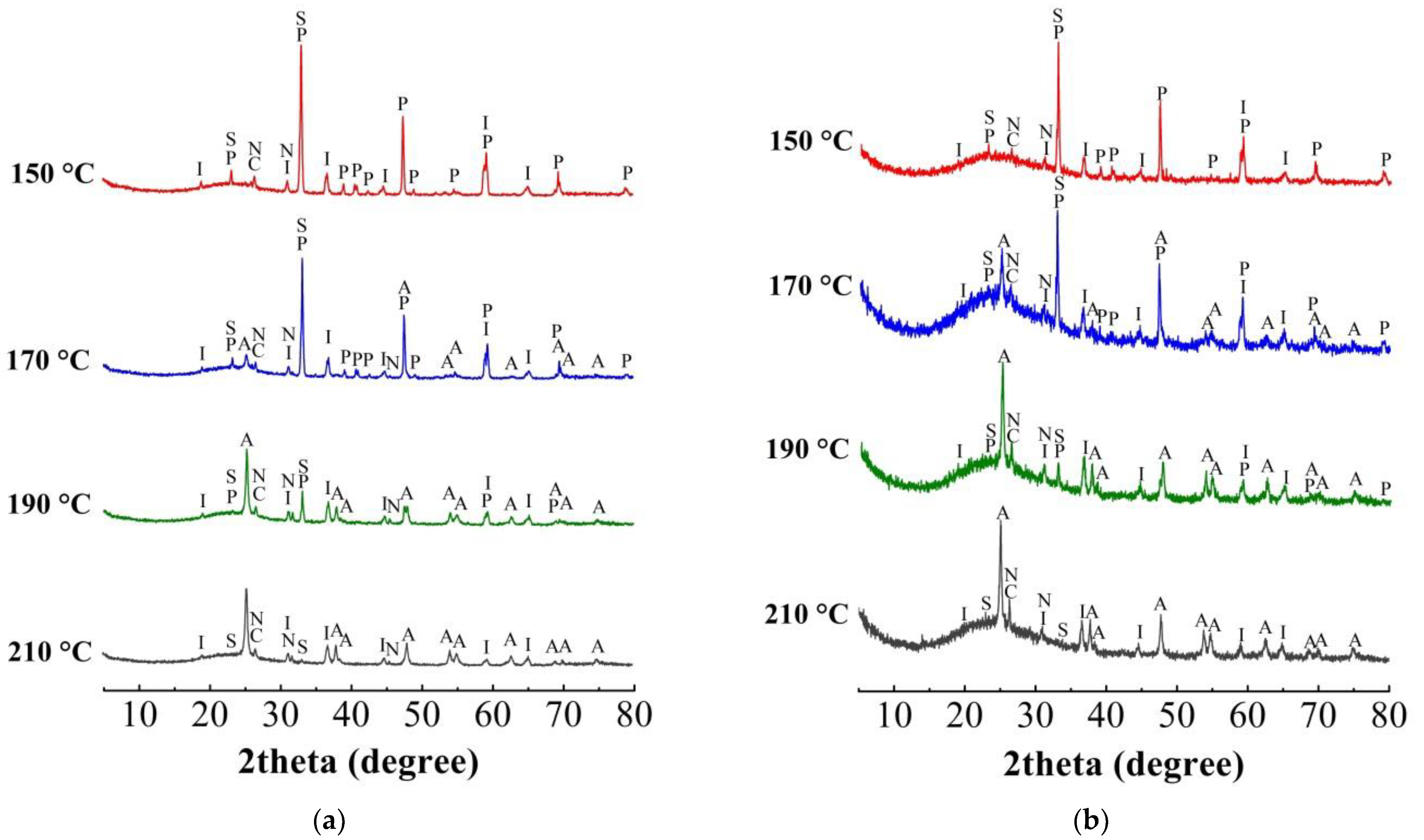
Figure 3 shows the XRD patterns of the residues of high-pressure hydrochloric acid leaching under fixed conditions after heating up to the required temperature without holding (0 min) and after the holding of 15 min, respectively.
As can be seen from the XRD patterns, the main crystalline phases at all temperatures are perovskite, anatase, and spinel. The proportion of anatase, which is one of the polymorphic modifications of titanium dioxide, increases with a temperature rise; at the same time, perovskite fully passes into the solution at 210 °C both without holding (0 min) and during treatment for 15 min.
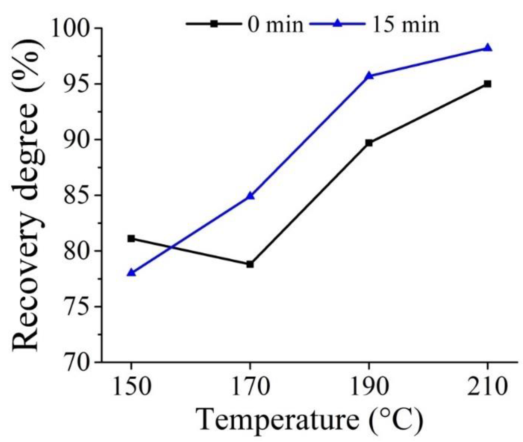
Figure 4 illustrates the effect of leaching temperature on calcium recovery degree that correlates with the XRD patterns (Figure 3). As reflected by the plot, the calcium recovery degree increases with rising temperature and treatment time. The recovery degree of Ca is above 90% and 95% at 210 °C for the treatment at 0 and 15 min, respectively. Hence, to decompose CaTiO3 fully, high-temperature treatment is favorable, which also leads to a higher dissolution of REEs and Ti concentration in the residue [44].
Sodium chloride, probably formed during vacuum filtration, is also present in the samples. It should be noted a significant content of the spinel phase in all the samples due to its stability [52], as well as elemental sulfur and graphite remaining after the reduction roasting of bauxite residue. The one aluminum-containing phase is spinel. Therefore, the other aluminum phases of the IDBR sample have already been dissolved upon the heating. The process of dissolution of Ti, Al, and Ca can be described as follows:
2CaO·TiO2(s) + 8HCl(l) = 2CaCl2(aq) + TiCl4(aq) + TiO2(s) + 4H2O(l)
2CaO·Al2O3·SiO2(s) + 10HCl(l) = 2AlCl3(aq) + 2CaCl2(aq) + SiO2(s) + 5H2O(l)
3MgO·Al2O3·3SiO2(s) + 12HCl(l) = 2AlCl3(aq) + 3MgCl2(aq) + 3SiO2(s) + 6H2O(l)
Thus, Si and Ti were precipitated during the leaching process and remained in the acid leaching residue almost fully. It is notable that yttrium and lanthanides mainly pass into the solution, while a major part of zirconium is retained in the residue. The detailed specifications of the behavior of elements are discussed in our previous paper [44].
There is a significant amorphous ring, which belongs to amorphous silica; it correlates with previous studies [53,54]. However, it should be noted that at 0 min of holding, the amorphous ring is still insignificant at all temperatures, while at 15 min, it is substantially larger (Figure 3). This fact suggests that the main stage of SiO2 precipitation occurs during the holding.
Based on the results of the XRD analyses, to precipitate silicon and titanium dioxides, we chose optimal conditions of high-pressure hydrochloric acid leaching: temperature is 210 °C, time is 15 min, the concentration of acid is 10%, and L/S ratio is 11. The sample for further treatment was prepared by an accumulation of the residues from 30 similar experiments at these conditions. Table 3 shows its chemical composition; Figure 5 demonstrates the XRD pattern.
As follows from the composition and the XRD pattern, the acid leaching residue has a considerable Si content, which is in the form of amorphous silica. Titanium is mainly in anatase form with a small amount of perovskite. Thus, amorphous silica, which is highly soluble in alkaline solutions, can be dissolved by NaOH leaching; thereby, the solid residue can be enriched in titanium.

3.2. Alumina Precipitation

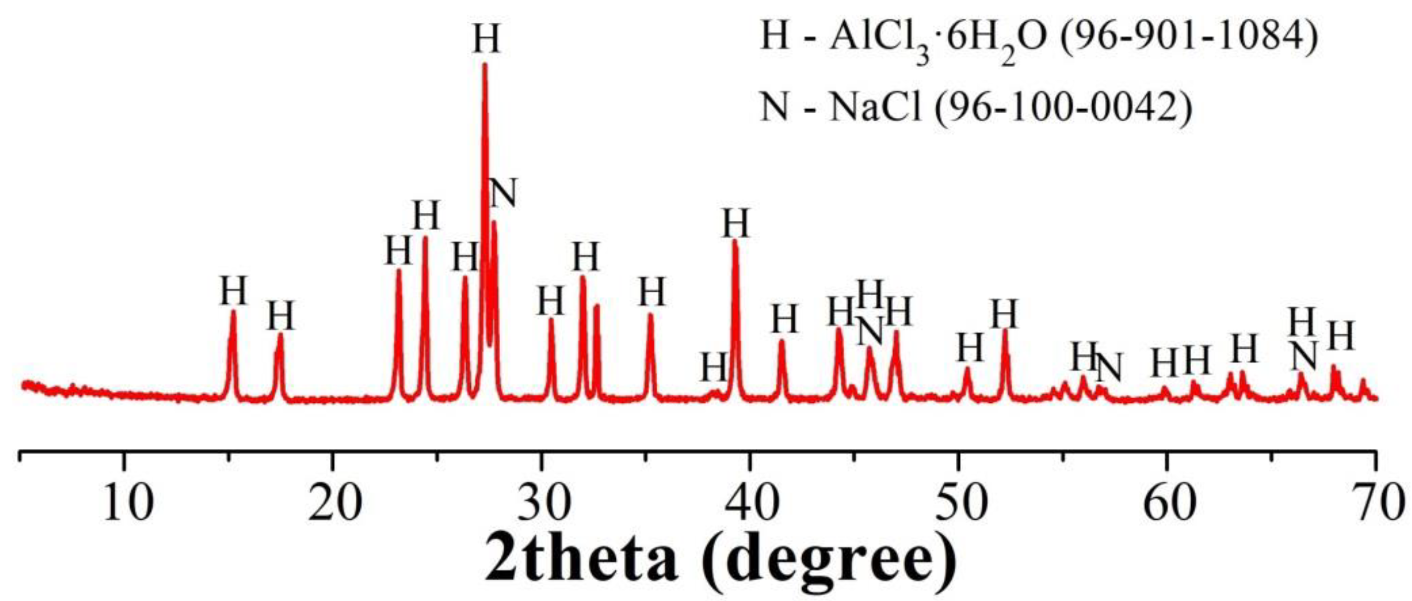
To study the process of alumina precipitation, we used the mother liquor from the hydrochloric acid leaching of IDBR; Table 4 indicates its composition. Table 5 shows the chemical composition of the precipitated ACH from the mother liquor. Figure 6 illustrates the XRD pattern of the precipitated ACH by HCl saturation.
As follows from the XRD pattern, the precipitate contains a significant amount of NaCl besides ACH. This fact makes an additional stage necessary to remove NaCl during further treatment. However, it should be noted that other elements such as Ca, Fe, Mg, and Mn mainly remain in the solution; this fact enables selective aluminum recovery.
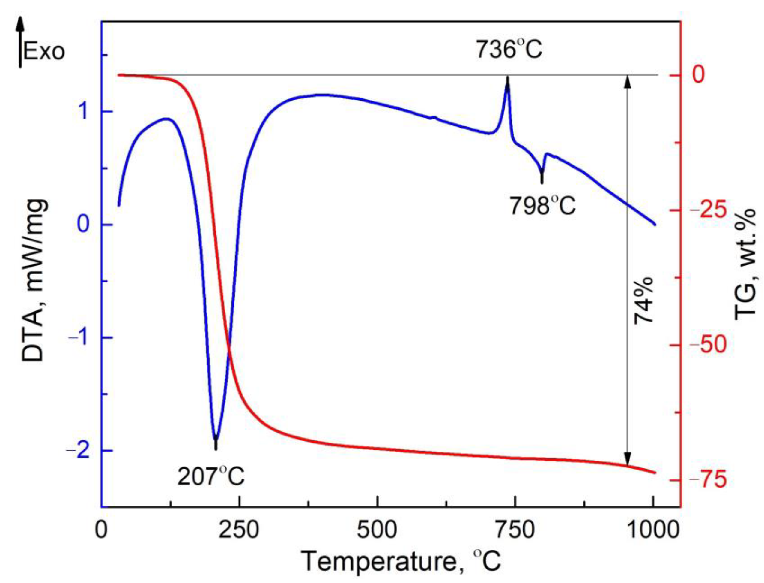
In order to elucidate the behavior of the precipitated ACH during calcination, simultaneous thermal analysis was carried out. Figure 7 shows TG-DTA curves of the precipitated ACH in the range of 25–1000 °C.
The first endo-effect at 207 °C with the major mass loss is clearly related to the decomposition of ACH to form amorphous Al2O3 [55]. The exothermic peak at 736 °C is responsible for the transition from amorphous Al2O3 to γ-Al2O3 [56]. The endothermic peak at 798 °C is apparently the melting point of NaCl [57]. Based on the results of TG-DTA analysis, we chose the temperature of ACH calcination as 800 °C to obtain γ-Al2O3.
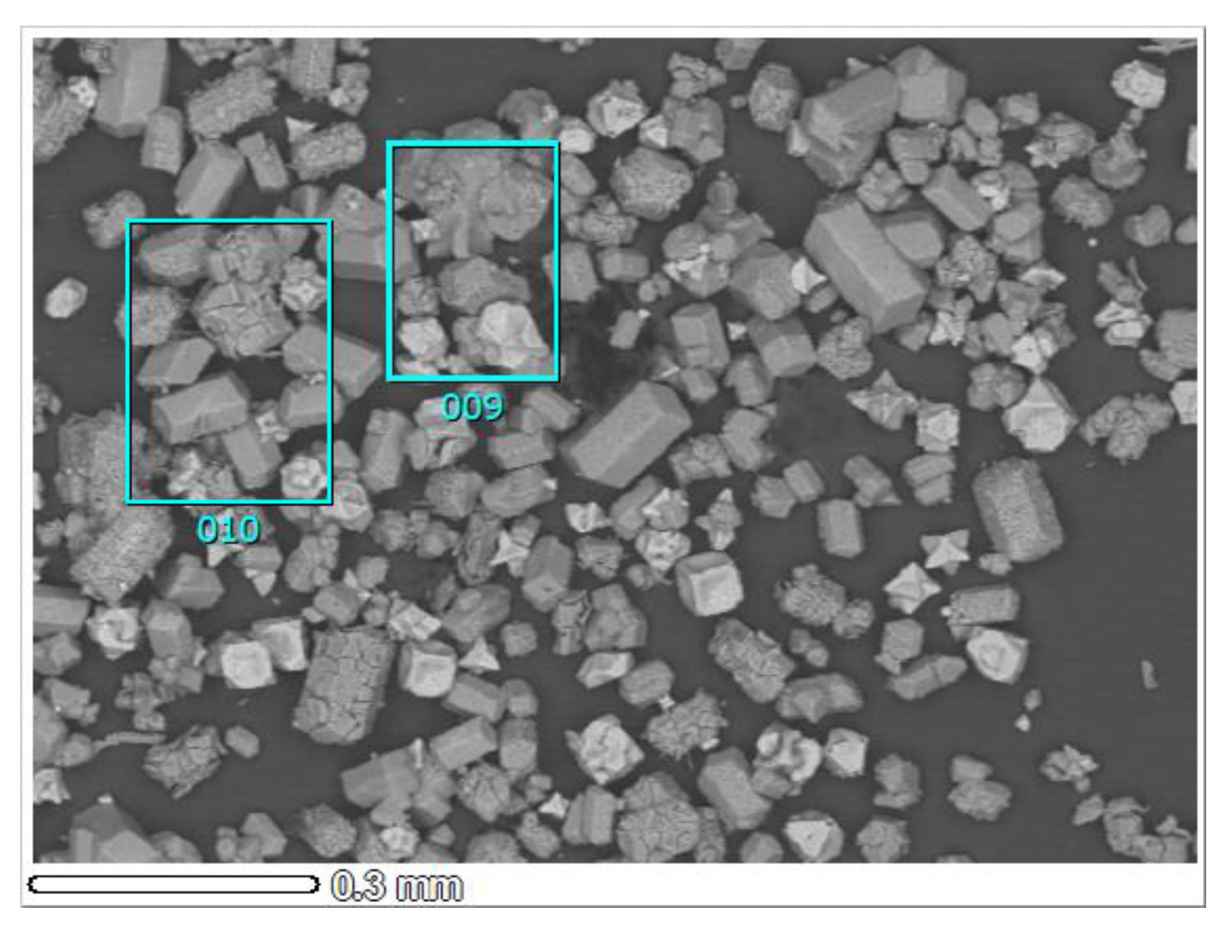
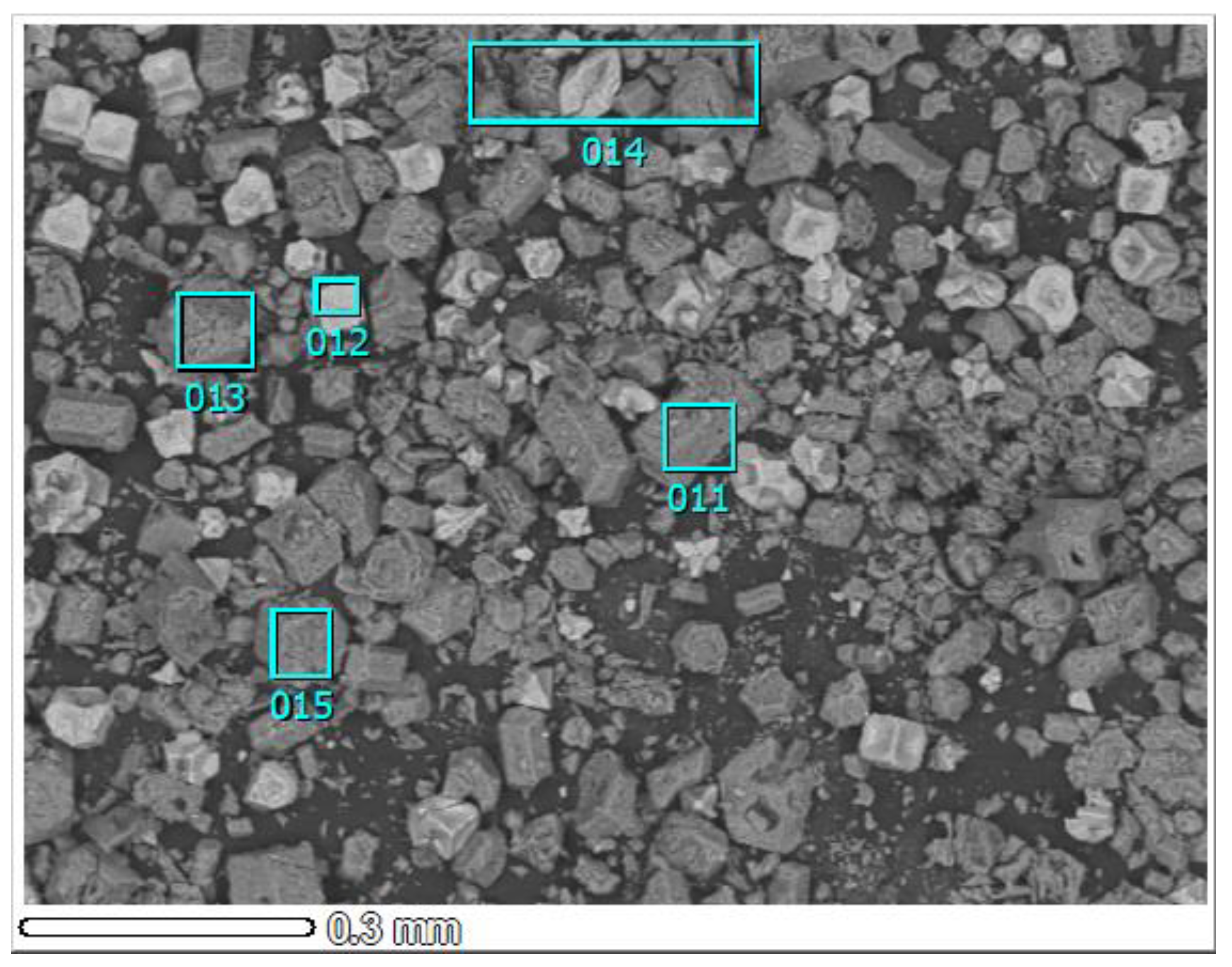
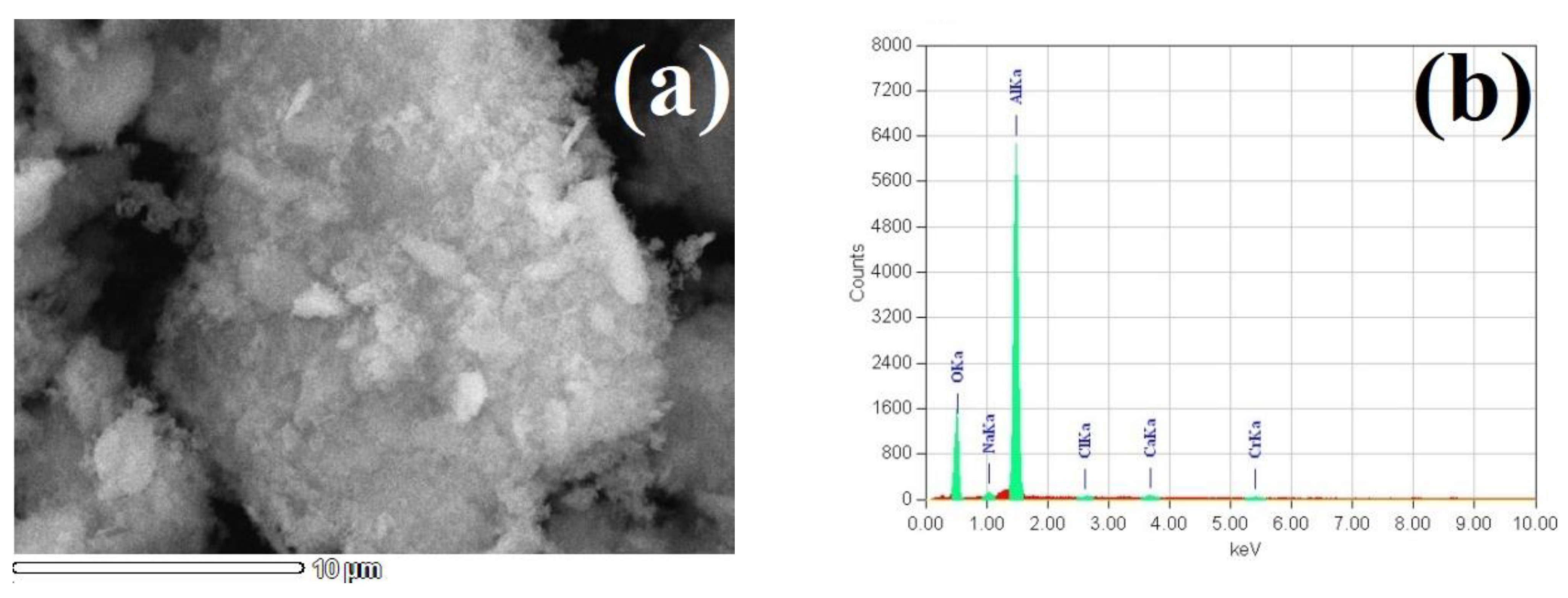
Figure 8 demonstrates the XRD patterns of Al2O3 prepared by calcination of the precipitated ACH, as well as by calcination of the precipitated ACH, water washing to remove sodium chloride, and repeated calcination. The patterns indicate that the calcined sample contains NaCl and γ-Al2O3 (Figure 8a). SEM confirmed the presence of crystalline AlCl3·6H2O and NaCl in the precipitated ACH sample (Figure A1). The crystal morphology is also inherited from the ACH sample after its calcination at 800 °C (Figure A2, Table A1). In order to remove soluble sodium chloride and chromium compounds, the water washing of the calcined Al2O3 sample was applied. This treatment led to the complete destruction of the crystal morphology of alumina. The water washing of the calcined sample, followed by the additional calcination at 800 °C resulted in obtaining purer γ-Al2O3 (Figure 8c), which is confirmed by the SEM-EDX spectrum (Figure 9b) and determined more accurately by chemical analysis (Table 5).
Figure 9 demonstrates SEM images at different magnifications of the synthesized γ-Al2O3.
It can be observed that after the decomposition of the precursor, the aggregates of the formed γ-Al2O3 powder presented in the SEM image (Figure 9a) are small particles of flocculent form and have a uniform distribution of aluminum and oxygen. The highly developed surface of the obtained sample and its small particle size hinder a more complete removal of soluble impurities such as Na and Cl; their small residual contents are detected by the SEM-EDX method. In order to increase the removal degree of such elements, more thorough water washing of the calcined at 600–800 °C alumina should be applied.
A chemical analysis of the prepared γ-Al2O3 was carried out to compare this composition with the requirements for metallurgical alumina. Table 6 lists its chemical composition, specific surface area (Figure A3a) and the requirements according to [58].
As can be seen, the contents of impurities in the obtained alumina and the specific surface area vary significantly from the standard requirements. Therefore, an additional stage to remove impurities is required. Authors [59,60] proved that alkaline leaching followed by alumina precipitation and calcination is the most effective method to obtain metallurgical alumina. Moreover, the refinement process of impure alumina via the alkaline recrystallization by the conventional Bayer process is considered as more economically viable than the improvement of alumina precipitation from the hydrochloric acid solution [60].

3.3. Scandium Solvent Extraction

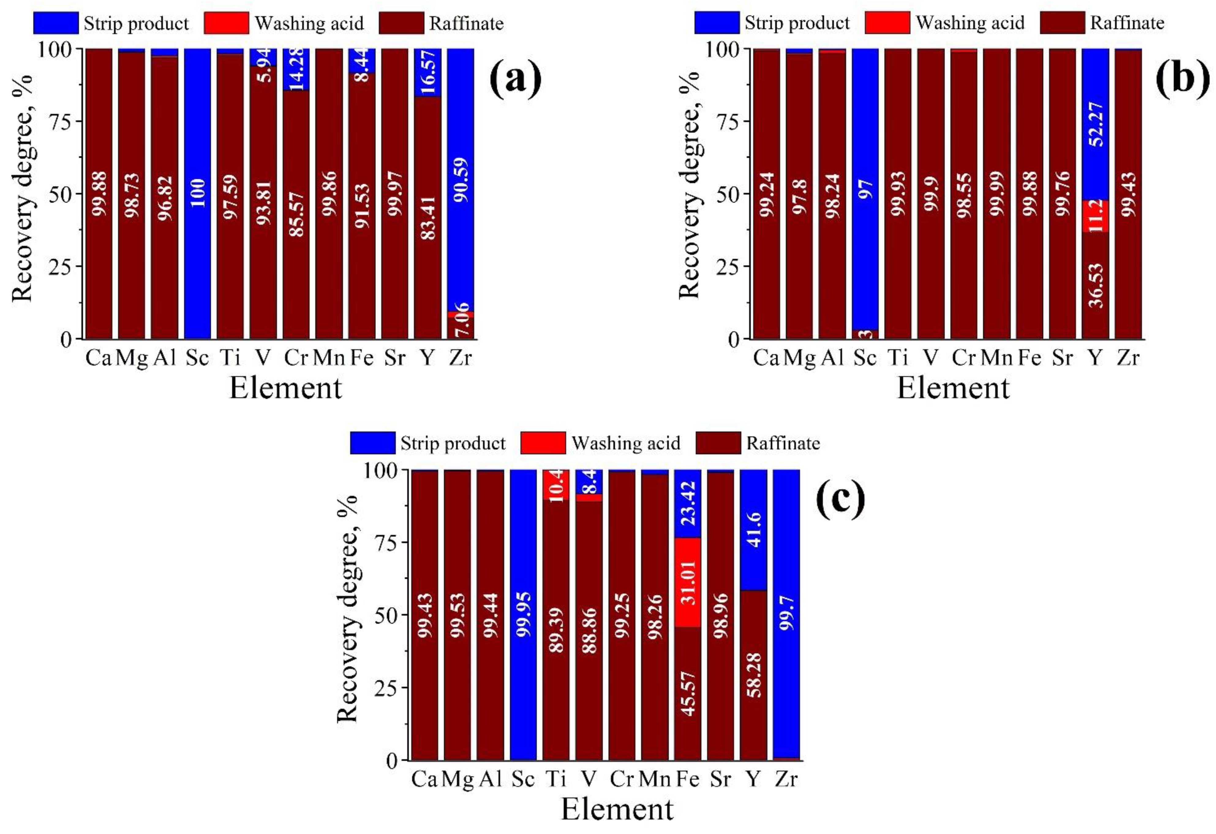
Three experiments using a mixture of 10% HDEHP and 2% TBP in kerosene were carried out according to the procedures described in Section 2.2.3. Table 7 shows the chemical composition of the prepared solutions that were used in the scandium solvent extraction experiments. These solutions were prepared according to Section 2.2.3. Figure 10 illustrates the distribution of metals at different stages in experiments 1–3.
As follows from the bar chart, almost full Sc recovery was in all the experiments. The best result is 99.95% Sc in the strip product in experiment 3. Yttrium and zirconium behavior are proved to be similar to scandium, but insignificant values of the Y and Zr recovery degree in the strip product in some experiments are probably due to their low content in the initial solution. A satisfactory separation of Fe and Ti is due to the prior preparation, namely, iron (III) reduction to iron (II) and titanium complexing in [TiO(H2O2)]2+, which is poorly soluble in the organic phase.
In experiment 1, scandium was stripped as a mixture of [Sc(OH)6]3− and Sc(OH)3 using 2 M NaOH at an O/A ratio of 1. The amount of the obtained scandium slurry was not enough to be separated by filtration, so it was diluted by sulfuric acid. The analysis of the obtained sulfuric acid solution has shown that V, Cr, Fe, Y, and Zr were partially leached out from the organic phase along with the rest of Sc after the alkaline treatment. Unfortunately, the scandium concentrate was not prepared in this experiment directly by stripping. It should be noted that all the stripped metals during the neutralization of an alkaline medium can form insoluble hydroxides. Therefore, after the subsequent calcination, impure scandium oxide can be prepared. However, in this experiment, their presence in the solution is likely due to a relatively high analysis error and their low initial content.
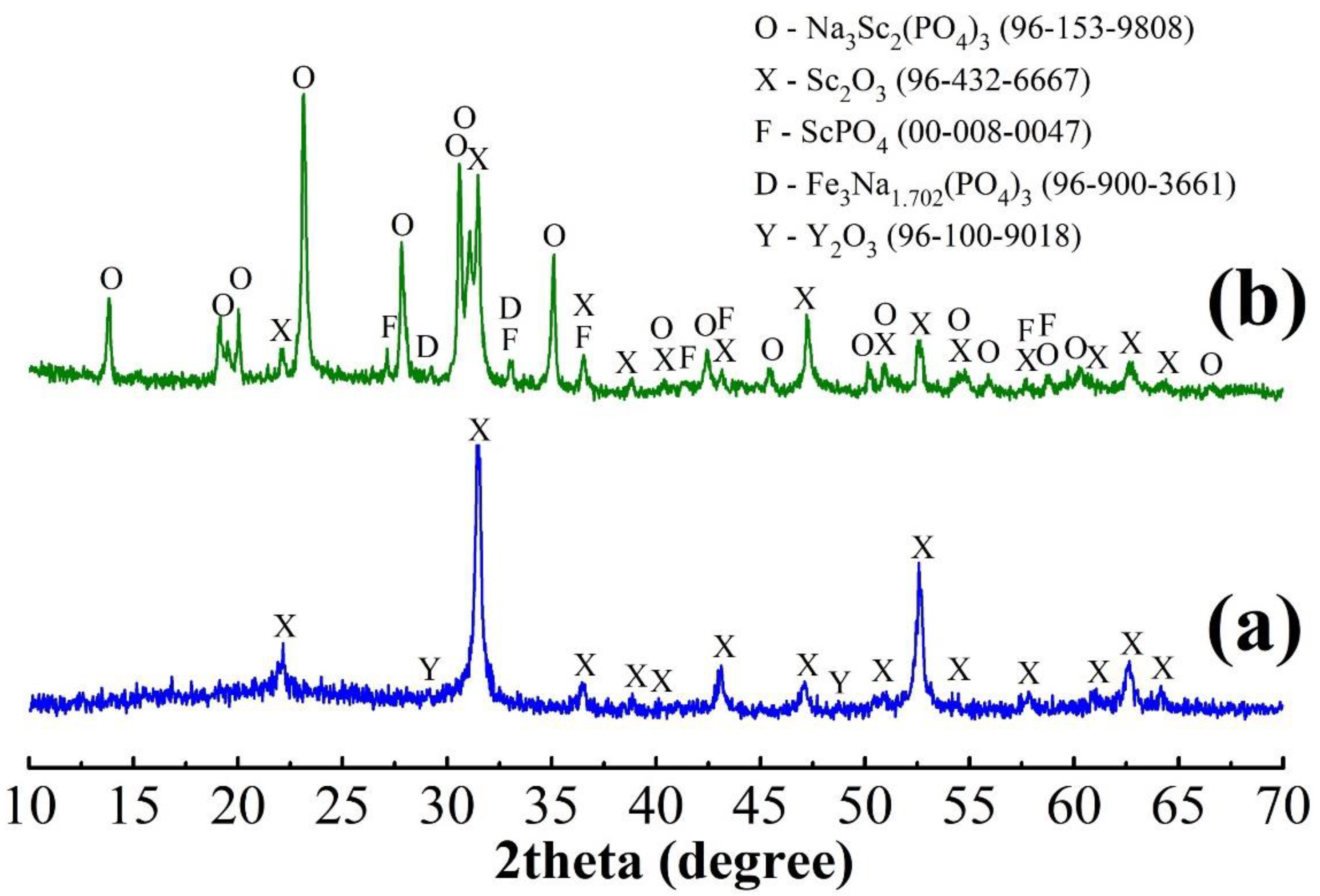
In exp. 2, scandium was stripped using a mixture of 0.5 M H2SO4 and 25 M HF at an O/A ratio of 1. Scandium fluoride in the strip aqueous solution was obtained as a slurry, which was impossible to separate completely. In order to precipitate scandium as Sc(OH)3, the slurry solution was neutralized with ammonia. As a result, a loose scandium-containing precipitate was deposited, which was easily separated by filtration; it was calcined to obtain scandium oxide and then analyzed by XRD (Figure 11). In contrast to exp. 1, only yttrium was stripped and co-precipitated with scandium in exp. 2; faint peaks of Y2O3 along with strong Sc2O3 peaks were detected in the XRD pattern.
In exp. 3, difficult-to-separate Sc2(C2O4)3 was formed by stripping using the mixture of ammonium oxalate and oxalic acid. Despite the insolubility of Sc2(C2O4)3 in water, scandium was precipitated incompletely. Probably, a soluble complex of (NH4)Sc(C2O4)2 was formed in the presence of an excess of oxalate ions, namely, the stable anion Sc(C2O4)2 [61]. The addition of a two-phase system of precipitate-forming fluoride ions of lower concentration compared to exp. 2 led to the appearance of a white suspension immiscible with neither organic nor aqueous phases. This suspension was separated by centrifugation, and then it was analyzed after calcination at 1000 °C by XRD. As can be seen from the XRD pattern (Figure 11), the calcined precipitate consists of a mixture of scandium oxide and phosphate, as well as thermally stable scandium-sodium double phosphate Na3Sc2(PO4)3. Accordingly, the created conditions led to the formation of a stable and insoluble compound in these media, which indicates a strong affinity of scandium for phosphate groups. It emphasizes the preference of the extraction system based on HDEHP. Iron and yttrium were found as impurities that are consistent with the series Sc3+ > Fe3+ > Lu3+ > Yb3+ > Er3+ > Y3+ > Ho3+, which is well-known for the recovery of metals from acidic solutions using HDEHP [46].
It should be noted that during stripping using sodium hydroxide, a white flocculent scandium precipitate is partially mixed with the organic phase, thereby decreasing the efficiency of the phase separation. An increase in the NaOH concentration can promote the formation of more water-soluble sodium salts with HDEHP, according to Equation (6), which leads to a significant loss of the organic phase.
HSc(SO4)2∙4HR + 8NaOH = Sc(OH)3↓+ 2Na2R2 + 2Na2SO4 + 5H2O
In order to reuse the extractant, its neutralization and sulfation should be carried out, which also leads to the deterioration of expensive HDEHP.
The intentional introduction of the bulk of Sc in the experiments was used due to the impossibility of obtaining a substantial amount of rich scandium concentrate directly from the solution after the ACH precipitation in a single processing cycle at the tested conditions. To achieve as high a grade of concentrate as possible, we suggest considering the following solutions:
  • Accumulation of scandium by several technological cycles;
  • Multiple reuses of the extractant amount;
  • Increasing the O/A ratio at the extraction stage;
  • Decreasing the O/A ratio at the stripping stage.
It is important to emphasize that although the direct precipitation of scandium hydroxide is proven to be rather efficient [62], less corrosive media for scandium stripping from the loaded organic phase instead of a highly alkaline solution is recommended to apply.
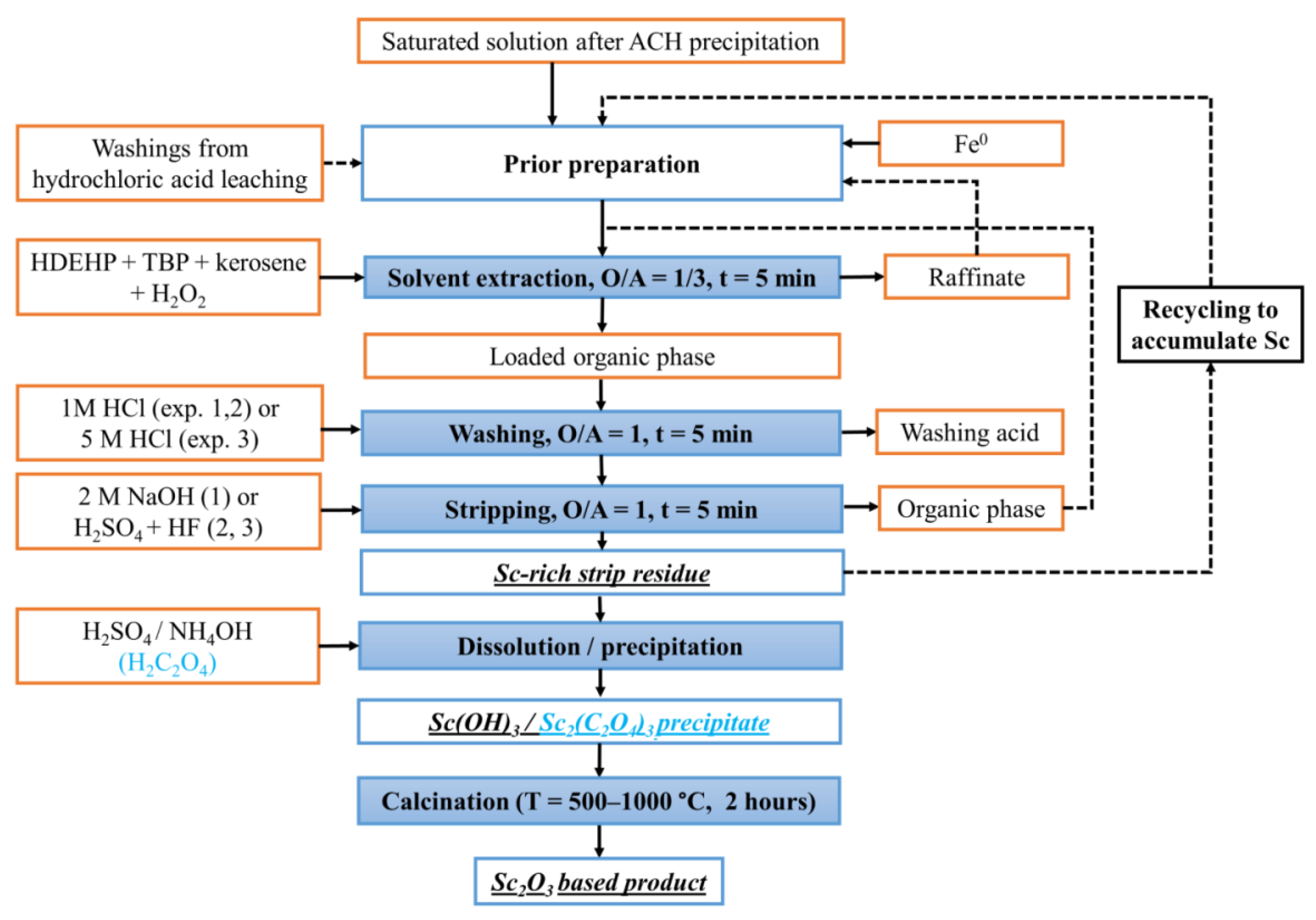
Figure 12 shows the sequence of scandium extraction procedures from the hydrochloric acid solution combined for three different experiments. The important and distinctive stages are the treatment of the solution with metallic iron and the introduction of H2O2 into the extraction mixture to reduce the effect of Fe and Zr impurities, washing with aqueous acid solutions (preferably using 5 M HCl) to reduce the contents of iron, aluminum, titanium, and others in the loaded organic phase, stripping to obtain a solid residue and its calcination to prepare scandium oxide.
In comparison with three different experiments, a concentrate containing 94% Sc2O3 was obtained only in exp. 2 owing to the high stripping degree of scandium from the organic phase using the acid mixture with the presence of HF. The following reprecipitation of scandium as Sc(OH)3 with ammonia is preferred compared with Sc2(C2O4)3 due to the lower required calcination temperature to produce Sc2O3.

3.4. Obtaining Titanium Concentrate

Table 8 and Figure 13 show the chemical composition and the XRD pattern, respectively, of the titanium concentrate prepared by alkaline leaching of the acid residue (Figure 1).
Ti content in the titanium concentrate after the alkaline leaching increased significantly compared with the acid residue, while Si content considerably lowered. The phase composition mainly includes anatase, so this product can be used as a universal raw material for the further production of TiO2 [63].
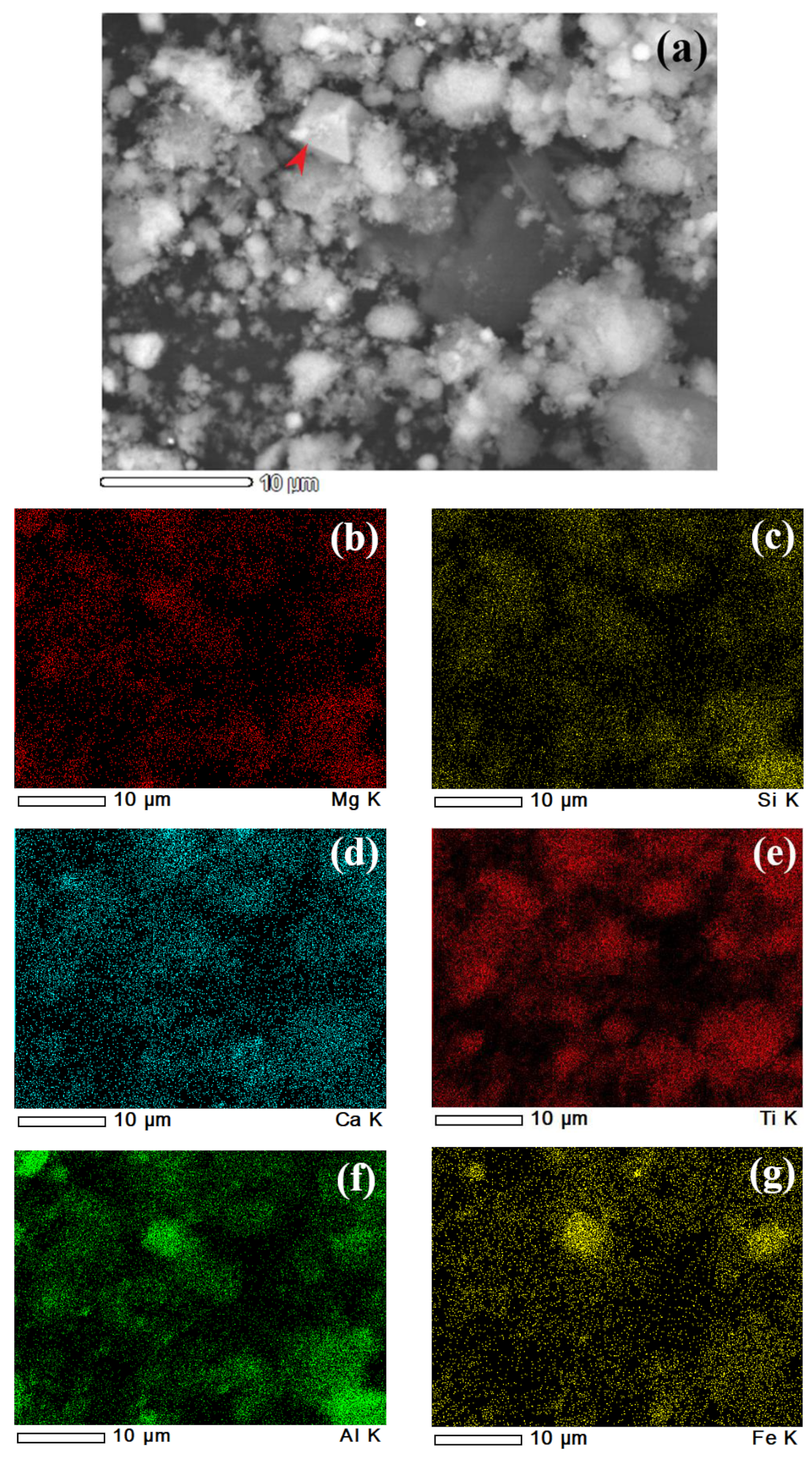
Figure 14 demonstrates SEM images of the titanium concentrate with the distribution of elements detected by the EDX device.
It is found that Si, Ti, and Ca are rather evenly distributed in the sample. On the other hand, Al, Mg, and Fe have a correlation among them that agrees well with the XRD pattern (Figure 13), where spinel phases were identified. A specific particle of Al–Mg–Fe spinel is marked in red in the SEM image.
It should be noted that the concentrate can be enriched more in titanium either by improvement of treatment processes or application of additional stages. Particularly, it is reported [52] that the formation of spinel during the roasting process is possible to prevent by adding 16% NaBO3. The presence of a significant graphite amount in the sample can reduce costs for further concentrate processing by chlorination method [64]. High contents of zirconium, yttrium, and strontium deserve consideration for their recovery along with titanium.

3.5. Preparation of Amorphous Silica Product (White Carbon)

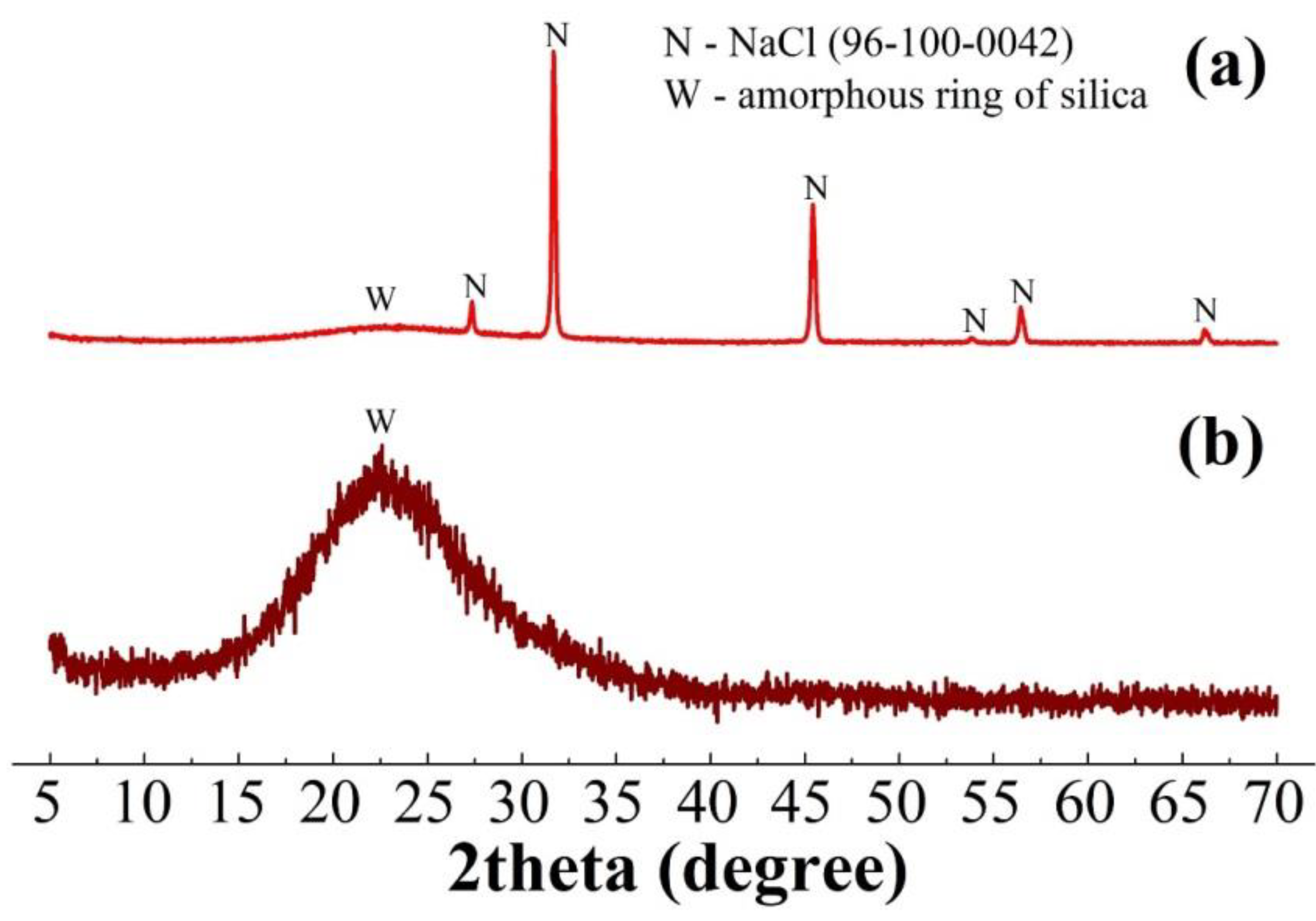
To precipitate SiO2, we neutralized the silicate solution of the alkaline leaching by 20% HCl. Figure 15 illustrates the XRD patterns of the precipitate before and after water leaching.
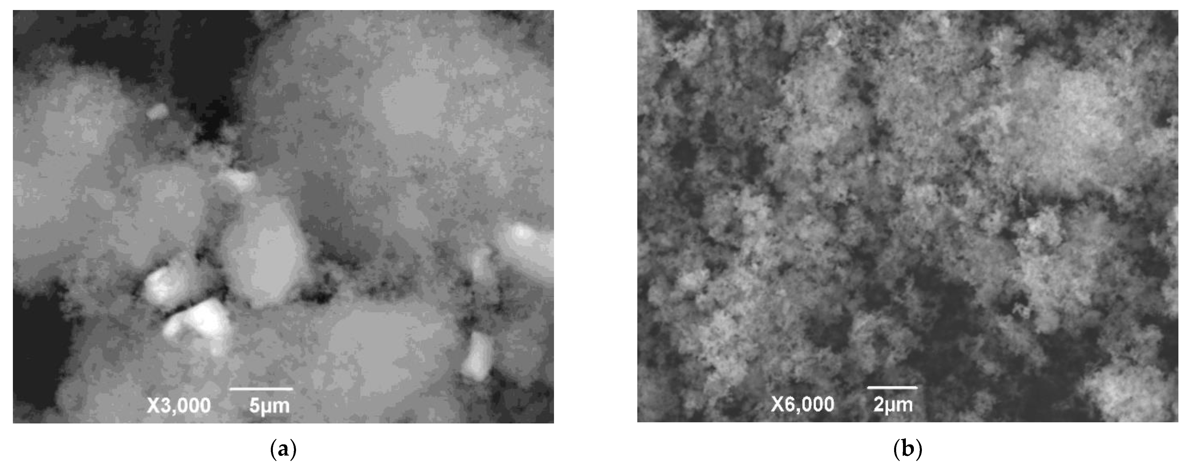
As can be seen from the presented XRD patterns of the white carbon, water leaching of the precipitate led to the removal of the unwanted impurity NaCl. Any other phase is absent in the XRD pattern. The amorphous ring of silica strongly correlates with the one from the other study [54], where white carbon was also obtained. Figure 16 clearly demonstrates a difference in SEM photomicrographs of the precipitated white carbon before and after water leaching. According to BET measurements (Figure A3b), the specific surface area of white carbon is about 25 m2/g before water leaching and about 50 m2/g after water leaching, which is rather anticipated from the SEM data (Figure 16).
Table 9 compares the composition and properties of the prepared white carbon with standard requirements.
As can be seen from the given data, according to the main part of properties, the obtained white carbon corresponds to the state standard. There is a discrepancy only on a few indicators, namely, loss of ignition, the contents of Al2O3 and Fe2O3 for BS–50 grade, as well as SiO2 content and specific surface area for BS–30 grade. Therefore, to comply with the standard, either a change in experimental conditions of the precipitation should be examined, or an additional refinement stage should be required. However, due to a slight difference in the standard, specifications for even such material can be agreed upon with a consumer.

3.6. Flowsheet Characterization

Figure 17 demonstrates a flowsheet of the main streams of IDBR processing with the indicated recovery degrees of scandium, aluminum, titanium, and silicon. As follows from the presented data, each stage proved to be quite effective. Titanium and silicon were mainly segregated selectively into titanium concentrate and white carbon with total recovery degrees of 81.3% and 88%, respectively.
High-pressure hydrochloric acid leaching is a crucial step to separate Ti and Si by 91.4 and 99.8%, respectively, into the acid residue and to dissolve the main part of Sc and Al. Although 19.6% Al, which includes the spinel phase, and 21% Sc, which is probably associated with titanium and zirconium, remained in the residue, their major part passed into liquid leaching products. It is notable that the Sc recovery degree in the washings is even higher than in the mother liquor, which undoubtedly required optimization. One of the optimization ways is the utilization of the washings to dilute the saturated solution for the solvent extraction stage (dashed arrow 1, Figure 17). This approach can lead to decreasing Sc losses while Al from the washings remains unextracted into ACH. Another way for the optimization is blending the washings and the mother liquor for the saturation stage (dashed arrow 1, Figure 17), which can lead to keeping both Sc and Al in the flowsheet for the recovery, but the saturation stage performance, in this case, can be reduced due to multiple increasing volumes of the charge solution and hydrochloric acid demand. The washings utilization method should be chosen and optimized on a pilot scale.
The saturation process enabled us to precipitate aluminum from the mother liquor almost fully and to obtain crude alumina. A minor part of Sc was precipitated along with Al and passed into crude alumina, which led to scandium loss. Solvent extraction of Sc from the saturated solution is proved to be effective due to its high recovery degree.
Table 10 clearly demonstrates enrichment ratios of valuable products obtained. The enrichment ratio of any element was calculated with respect to bauxite residue (KBR) and IDBR (KIDBR) as follows:
KBR = W/WBR × 100,
KIDBR = W/WIDBR × 100,
where WBR, WIDBR, and W—content of elements in the bauxite residue, IDBR (Table 1), and in the corresponding obtained product (scandium concentrate, alumina, titanium concentrate, white carbon), respectively, wt.%
The presented results show that Al, Ti, and Si in the corresponding products were enriched by a factor of about 3–4 and 7–9 from IDBR and bauxite residue, respectively; several thousandfold Sc enrichments were achieved. These values confirm the high selectivity and efficiency of the recovery of the elements using the flowsheet.

4. Discussion

Experimental results have shown the feasibility of the IDBR treatment by the developed flowsheet with obtaining valuable products such as scandium concentrate, crude alumina, titanium concentrate, and white carbon. A rather similar process for bauxite residue treatment has been proposed before by Orbite Aluminae Inc. (Montreal, Canada) [65]. However, an attempt to commercialize the process was unsuccessful. In our opinion, the Orbite process has a significant disadvantage related to the absence of an iron recovery stage via the reduction roasting–magnetic separation approach, which was successfully commercialized in China [20]. Table 11 clearly compares the process applied in this study with the one from Orbite Aluminae Inc. A bauxite residue treatment by direct hydrochloric acid leaching requires the application of strong HCl and its excessive consumption due to associated iron dissolution that also leads to the complicated extraction of REEs. In addition, this approach treats raw materials depleted in valuable elements that, as a result, can lead to lower productivity of the process, a significant increase in the amount of metallic iron added at the extraction stage, a possible quality deterioration of scandium and titanium concentrates, alumina, and white carbon due to impurity contamination.
Hence, the approach based on direct hydrochloric acid leaching is preferable for aluminum raw materials with lower iron content, such as coal fly ash [66], nepheline ore [67], high silicon bauxite [68], etc.
Our previous papers [45,69] have shown that an iron concentrate obtained by iron depletion via the carbothermic roasting–magnetic separation process can contain more than 90% Fe in metallic form. Therefore, such an iron concentrate can be considered for use at the scandium extraction stage to reduce iron from Fe3+ to Fe2+.
The developed flowsheet can involve additional stages for the recovery of other components such as V, Y, Li, Nd, Zr, Sr, etc., which are also present in bauxite residue [70]. In our case, the processing of the titanium concentrate to extract Ti, Y, Sr, and Sc is one of the promising directions for future research. Moreover, liquid glass instead of white carbon can be obtained [54]. Anyway, various options for the developed flowsheet can be considered depending on the chemical composition of bauxite residue, market demand, product cost, logistics capabilities, and other factors.

5. Conclusions

The flowsheet for the recovery of valuable elements from IDBR based on hydrochloric high-pressure acid leaching, aluminum precipitation by saturation of the acid leachate, solvent extraction of scandium using the mixture of HDEHP and TBP, alkaline leaching of the acid residue with subsequent silica precipitation has been first realized on a laboratory scale. The main results were as follows:
  • The high-pressure hydrochloric leaching using 10% HCl at an L/S ratio of 11 for 15 min led to 79% Sc and 79.9% Al dissolution, while 91.4% Ti and 99.8% Si remained in the acid residue;
  • The saturation of the acid leaching liquor by gaseous HCl in an argon flow for 30 min brought to ACH precipitation; after the ACH calcination at 800 °C and a subsequent water washing, the impure alumina of 93.5% Al2O3 was obtained, which was suitable for refinement by the conventional Bayer process;
  • Solvent extraction of scandium from the acid leaching solution after the ACH precipitation and preliminary iron reduction from Fe3+ to Fe2+ was carried out using 10% HDEHP and 2% TBP in kerosene at an O/A ratio of 1/3 for 10 min with subsequent sequential stripping by oxalate mixture and 25 M HF at O/A ratio of 1/1 for 5 min; as a result, a valuable concentrate of 94% Sc2O3 was obtained;
  • Alkaline leaching of the acid residue using 5 M NaOH at an L/S ratio of 12 for 90 min with following silica precipitation by adjusting pH to 8.5, its filtration and drying led to the preparation of white carbon of 77% SiO2 with a slight deviation from relevant standards.
The developed flowsheet can be used for the comprehensive recycling of hazardous alumina waste to obtain several valuable products. The main advantages of the proposed method are decreased acid consumption and low impurity contamination of the products due to an absence of iron leaching and hydrolysis stages compared to the Orbite process. It is very important that, according to the flowsheet, the products can be obtained, which have a high market demand. The remaining points for subsequent study are reaching pigment quality titanium dioxide for titanium concentrate, purification of alumina and white carbon, and improvement of Sc2O3 grade. After sufficient flowsheet optimization on a laboratory scale, the cost-benefit analysis and large-scale verification can be carried out, and then commercialization can be considered.

Author Contributions

Conceptualization, P.G., L.P. and D.Z.; methodology, P.G., L.P. and D.Z.; software, P.G. and L.P.; validation, P.G., L.P. and D.Z.; formal analysis, P.G., L.P. and A.Y.; investigation, P.G., L.P. and A.Y.; resources, V.D.; data curation, P.G.; writing—original draft preparation, P.G. and L.P.; writing—review and editing, D.Z. and A.Y.; visualization, P.G., L.P. and D.Z.; project administration, D.Z. and V.D. All authors have read and agreed to the published version of the manuscript.

Funding

This research was funded by RFBR, grant number 18–29–24186. Access to the electronic database of scientific publications was provided within the Russian state assignment, number 075-00715-22-00. L.P. acknowledges the support of the state order via the Ministry of Science and High Education of Russia, number AAAA-A19-119031890028-0.

Data Availability Statement

Data sharing is not applicable.

Acknowledgments

The authors wish to express their thanks to Alexander Petelin for funding acquisition and supervision. The authors would like to thank the Chemical Analytical Laboratory of the JSC “Design & Survey and Research & Development Institute of Industrial Technology” for chemical analysis.

Conflicts of Interest

The authors declare no conflict of interest.

Appendix A

Figure A1 and Figure A2 clearly demonstrate the microstructure of the precipitated ACH sample and Al2O3 prepared from the ACH sample, respectively. Table A1 lists the composition of the areas outlined in Figure A1 and Figure A2.
Figure A1. SEM image of ACH precipitated from the mother liquor with the outlined analyzed areas by EDX (the XRD pattern is Figure 6).
Crystals 12 01578 g0a1
Figure A2. SEM image of the Al2O3 sample obtained by calcination of ACH at 800 °C for 60 min in the air with the outlined analyzed areas by EDX (the XRD pattern is Figure 8a).
Crystals 12 01578 g0a2
Table A1. The elemental composition of the outlined areas from Figure A1 and Figure A2 measured by EDX.
Memo009010011012013014015
O25.728.831.85.535.626.734.9
Na6.84.30.927.60.57.00.3
Al11.613.351.23.148.136.751.1
Cl54.351.911.763.810.824.89.7
Ca0.50.70.00.00.40.60.0
Cr1.11.04.40.04.23.84.0
Fe0.00.00.00.00.40.40.0
Total (wt.%)100.0100.0100.0100.0100.0100.0100.0
Figure A3 illustrates the adsorption isotherms for the impure alumina sample, as well as for the white carbon samples before and after water washing.
Figure A3. Adsorption isotherms of N2 at 77 K for impure alumina obtained at the conditions of Figure 8c (a) and for white carbon before and after water leaching (b).
Crystals 12 01578 g0a3

References

  1. West, J. Decreasing Metal Ore Grades: Are They Really Being Driven by the Depletion of High-Grade Deposits? J. Ind. Ecol. 2011, 15, 165–168. [Google Scholar] [CrossRef]
  2. Goodenough, K.M.; Wall, F.; Merriman, D. The Rare Earth Elements: Demand, Global Resources, and Challenges for Resourcing Future Generations. Nat. Resour. Res. 2018, 27, 201–216. [Google Scholar] [CrossRef] [Green Version]
  3. Pistilli, M. Why Scandium Could Be a Huge Opportunity. Available online: https://investingnews.com/daily/resource-investing/critical-metals-investing/scandium-investing/scandium-production-the-problem-and-the-opportunity/ (accessed on 2 December 2021).
  4. Borra, C.R.; Pontikes, Y.; Binnemans, K.; Van Gerven, T. Leaching of Rare Earths from Bauxite Residue (Red Mud). Miner. Eng. 2015, 76, 20–27. [Google Scholar] [CrossRef] [Green Version]
  5. Gaustad, G.; Williams, E.; Leader, A. Rare Earth Metals from Secondary Sources: Review of Potential Supply from Waste and Byproducts. Resour. Conserv. Recycl. 2021, 167, 105213. [Google Scholar] [CrossRef]
  6. Reddy, P.S.; Reddy, N.G.; Serjun, V.Z.; Mohanty, B.; Das, S.K.; Reddy, K.R.; Rao, B.H. Properties and Assessment of Applications of Red Mud (Bauxite Residue): Current Status and Research Needs. Waste Biomass Valoriz. 2021, 12, 1185–1217. [Google Scholar] [CrossRef]
  7. Wang, S.; Jin, H.; Deng, Y.; Xiao, Y. Comprehensive Utilization Status of Red Mud in China: A Critical Review. J. Clean. Prod. 2021, 289, 125136. [Google Scholar] [CrossRef]
  8. Healy, S. Sustainable Bauxite Residue Management Guidance. Available online: https://international-aluminium.org/wp-content/uploads/2021/10/BRManagementGuidance.pdf (accessed on 1 October 2022).
  9. Qi, Y. The Neutralization and Recycling of Red Mud—A Review. J. Phys. Conf. Ser. 2021, 1759, 012004. [Google Scholar] [CrossRef]
  10. Gräfe, M.; Power, G.; Klauber, C. Bauxite Residue Issues: III. Alkalinity and Associated Chemistry. Hydrometallurgy 2011, 108, 60–79. [Google Scholar] [CrossRef]
  11. Alam, S.; Das, B.K.; Das, S.K. Dispersion and Sedimentation Characteristics of Red Mud. J. Hazard. Toxic. Radioact. Waste 2018, 22, 04018025. [Google Scholar] [CrossRef]
  12. Xue, S.; Zhu, F.; Kong, X.; Wu, C.; Huang, L.; Huang, N.; Hartley, W. A Review of the Characterization and Revegetation of Bauxite Residues (Red Mud). Environ. Sci. Pollut. Res. 2016, 23, 1120–1132. [Google Scholar] [CrossRef]
  13. Di Carlo, E.; Boullemant, A.; Courtney, R. A Field Assessment of Bauxite Residue Rehabilitation Strategies. Sci. Total Environ. 2019, 663, 915–926. [Google Scholar] [CrossRef] [PubMed]
  14. Li, S.; Zhang, Y.; Feng, R.; Yu, H.; Pan, J.; Bian, J. Environmental Safety Analysis of Red Mud-Based Cemented Backfill on Groundwater. Int. J. Environ. Res. Public Health 2021, 18, 8094. [Google Scholar] [CrossRef] [PubMed]
  15. Ren, J.; Chen, J.; Han, L.; Wang, M.; Yang, B.; Du, P.; Li, F. Spatial distribution of heavy metals, salinity and alkalinity in soils around bauxite residue disposal area. Sci. Total Environ. 2018, 628–629, 1200–1208. [Google Scholar] [CrossRef] [PubMed]
  16. Higgins, D.; Curtin, T.; Courtney, R. Effectiveness of a constructed wetland for treating alkaline bauxite residue leachate: A 1-year field study. Environ. Sci. Pollut. Res. 2017, 24, 8516–8524. [Google Scholar] [CrossRef] [PubMed]
  17. Evans, K. The History, Challenges, and New Developments in the Management and Use of Bauxite Residue. J. Sustain. Metall 2016, 2, 316–331. [Google Scholar] [CrossRef] [Green Version]
  18. Gelencsér, A.; Kováts, N.; Turóczi, B.; Rostási, Á.; Hoffer, A.; Imre, K.; Nyiró-Kósa, I.; Csákberényi-Malasics, D.; Tóth, Á.; Czitrovszky, A.; et al. The Red Mud Accident in Ajka (Hungary): Characterization and Potential Health Effects of Fugitive Dust. Environ. Sci. Technol. 2011, 45, 1608–1615. [Google Scholar] [CrossRef]
  19. Major Tailings Dam Failure in China’s Henan Province. Available online: https://watchers.news/2016/08/16/major-tailings-dam-failure-in-china-s-henan-province/ (accessed on 28 September 2021).
  20. Zeng, H.; Lyu, F.; Sun, W.; Zhang, H.; Wang, L.; Wang, Y. Progress on the Industrial Applications of Red Mud with a Focus on China. Minerals 2020, 10, 773. [Google Scholar] [CrossRef]
  21. Lyu, F.; Hu, Y.; Wang, L.; Sun, W. Dealkalization Processes of Bauxite Residue: A Comprehensive Review. J. Hazard Mater. 2021, 403, 123671. [Google Scholar] [CrossRef]
  22. Liu, Y.; Naidu, R. Hidden Values in Bauxite Residue (Red Mud): Recovery of Metals. Waste Manag. 2014, 34, 2662–2673. [Google Scholar] [CrossRef]
  23. Li, X.; Yu, S.; Dong, W.; Chen, Y.; Zhou, Q.; Qi, T.; Liu, G.; Peng, Z.; Jiang, Y. Investigating the Effect of Ferrous Ion on the Digestion of Diasporic Bauxite in the Bayer Process. Hydrometallurgy 2015, 152, 183–189. [Google Scholar] [CrossRef]
  24. Pasechnik, L.A.; Skachkov, V.M.; Bogdanova, E.A.; Chufarov, A.Y.; Kellerman, D.G.; Medyankina, I.S.; Yatsenko, S.P. A Promising Process for Transformation of Hematite to Magnetite with Simultaneous Dissolution of Alumina from Red Mud in Alkaline Medium. Hydrometallurgy 2020, 196, 105438. [Google Scholar] [CrossRef]
  25. Wang, L.; Sun, N.; Tang, H.; Sun, W. A Review on Comprehensive Utilization of Red Mud and Prospect Analysis. Minerals 2019, 9, 362. [Google Scholar] [CrossRef] [Green Version]
  26. Zinoveev, D.; Pasechnik, L.; Fedotov, M.; Dyubanov, V.; Grudinsky, P.; Alpatov, A. Extraction of Valuable Elements from Red Mud with a Focus on Using Liquid Media—A Review. Recycling 2021, 6, 38. [Google Scholar] [CrossRef]
  27. Kang, J.; Gao, L.; Zhang, M.; Pu, J.; He, L.; Ruan, R.; Omran, M.; Peng, J.; Chen, G. Synthesis of Rutile TiO2 Powder by Microwave-Enhanced Roasting Followed by Hydrochloric Acid Leaching. Adv. Powder Technol. 2020, 31, 1140–1147. [Google Scholar] [CrossRef]
  28. Pasechnik, L.A.; Skachkov, V.M.; Chufarov, A.Y.; Suntsov, A.Y.; Yatsenko, S.P. High Purity Scandium Extraction from Red Mud by Novel Simple Technology. Hydrometallurgy 2021, 202, 105597. [Google Scholar] [CrossRef]
  29. Rivera, R.M.; Xakalashe, B.; Ounoughene, G.; Binnemans, K.; Friedrich, B.; van Gerven, T. Selective Rare Earth Element Extraction Using High-Pressure Acid Leaching of Slags Arising from the Smelting of Bauxite Residue. Hydrometallurgy 2019, 184, 162–174. [Google Scholar] [CrossRef]
  30. He, S.; Wang, J.; Yan, J. Pressure Leaching of High Silica Pb-Zn Oxide Ore in Sulfuric Acid Medium. Hydrometallurgy 2010, 104, 235–240. [Google Scholar] [CrossRef]
  31. Zhu, X.; Li, W.; Tang, S.; Zeng, M.; Bai, P.; Chen, L. Selective Recovery of Vanadium and Scandium by Ion Exchange with D201 and Solvent Extraction Using P507 from Hydrochloric Acid Leaching Solution of Red Mud. Chemosphere 2017, 175, 365–372. [Google Scholar] [CrossRef] [PubMed]
  32. Ye, Q.; Li, G.; Deng, B.; Luo, J.; Rao, M.; Peng, Z.; Zhang, Y.; Jiang, T. Solvent Extraction Behavior of Metal Ions and Selective Separation Sc3+ in Phosphoric Acid Medium Using P204. Sep. Purif. Technol. 2019, 209, 175–181. [Google Scholar] [CrossRef]
  33. Wang, W.; Cheng, C.Y. Separation and Purification of Scandium by Solvent Extraction and Related Technologies: A Review. J. Chem. Technol. Biotechnol. 2011, 86, 1237–1246. [Google Scholar] [CrossRef]
  34. Zhu, X.; Niu, Z.; Li, W.; Zhao, H.; Tang, Q. A Novel Process for Recovery of Aluminum, Iron, Vanadium, Scandium, Titanium and Silicon from Red Mud. J. Environ. Chem. Eng. 2020, 8, 103528. [Google Scholar] [CrossRef]
  35. Singh, R.K.; Dhadke, P.M. Extraction and Separation Study of Scandium (III) from Perchlorate Media by D2EHPA and PC 88A. Bull. Chem. Technol. Maced. 2002, 22, 1–11. [Google Scholar]
  36. Botelho Junior, A.B.; Espinosa, D.C.R.; Tenório, J.A.S. Selective Separation of Sc(III) and Zr(IV) from the Leaching of Bauxite Residue Using Trialkylphosphine Acids, Tertiary Amine, Tri-Butyl Phosphate and Their Mixtures. Sep. Purif. Technol. 2021, 279, 119798. [Google Scholar] [CrossRef]
  37. Korovin, V.; Shestak, Y. Scandium Extraction from Hydrochloric Acid Media by Levextrel-Type Resins Containing Di-Isooctyl Methyl Phosphonate. Hydrometallurgy 2009, 95, 346–349. [Google Scholar] [CrossRef]
  38. Shirokova, A.G.; Pasechnik, L.A.; Yatsenko, S.P. Synthesis and Certain Properties of Extraction Microencapsulated Systems. Russ. J. Appl. Chem. 2013, 86, 675–679. [Google Scholar] [CrossRef]
  39. Salman, A.D.; Juzsakova, T.; Mohsen, S.; Abdullah, T.A.; Le, P.-C.; Sebestyen, V.; Sluser, B.; Cretescu, I. Scandium Recovery Methods from Mining, Metallurgical Extractive Industries, and Industrial Wastes. Materials 2022, 15, 2376. [Google Scholar] [CrossRef] [PubMed]
  40. Wang, W.; Pranolo, Y.; Cheng, C.Y. Recovery of Scandium from Synthetic Red Mud Leach Solutions by Solvent Extraction with D2EHPA. Sep. Purif. Technol. 2013, 108, 96–102. [Google Scholar] [CrossRef]
  41. Pyagay, I.; Medyankina, I.; Skachkova, O.; Yatsenko, A.; Pasechnik, L.; Skachkov, V.; Sabirzyanov, N. Extraction of Yttrium from Acidic Solutions [Ekstrakcionnoe Izvlechenie Ittriya Iz Kislyh Rastvorov]. Him. Tekhnologiya 2016, 17, 403–407. (In Russian) [Google Scholar]
  42. Salman, A.D.; Juzsakova, T.; Jalhoom, M.G.; Abdullah, T.A.; Le, P.-C.; Viktor, S.; Domokos, E.; Nguyen, X.C.; La, D.D.; Nadda, A.K.; et al. A Selective Hydrometallurgical Method for Scandium Recovery from a Real Red Mud Leachate: A Comparative Study. Environ. Pollut. 2022, 308, 119596. [Google Scholar] [CrossRef]
  43. Ditze, A.; Kongolo, K. Recovery of Scandium from Magnesium, Aluminium and Iron Scrap. Hydrometallurgy 1997, 44, 179–184. [Google Scholar] [CrossRef]
  44. Zinoveev, D.; Grudinsky, P.; Zhiltsova, E.; Grigoreva, D.; Volkov, A.; Dyubanov, V.; Petelin, A. Research on High-Pressure Hydrochloric Acid Leaching of Scandium, Aluminum and other Valuable Components from the Non-Magnetic Tailings Obtained from Red Mud after Iron Removal. Metals 2021, 11, 469. [Google Scholar] [CrossRef]
  45. Grudinsky, P.; Zinoveev, D.; Yurtaeva, A.; Kondratiev, A.; Dyubanov, V.; Petelin, A. Iron Recovery from Red Mud Using Carbothermic Roasting with Addition of Alkaline Salts. J. Sustain. Metall. 2021, 7, 858–873. [Google Scholar] [CrossRef]
  46. Qureshi, I.H.; McClendon, L.T.; LaFleur, P.D. Extraction Studies of the Group IIIB-VIIB Elements and the Lanthanides Utilizing Bis(2-Ethyl-Hexyl) Orthophosphoric Acid. Radiochim. Acta 1969, 12, 107–111. [Google Scholar] [CrossRef]
  47. Zhou, J.; Ning, S.; Meng, J.; Zhang, S.; Zhang, W.; Wang, S.; Chen, Y.; Wang, X.; Wei, Y. Purification of Scandium from Concentrate Generated from Titanium Pigments Production Waste. J. Rare Earths 2021, 39, 194–200. [Google Scholar] [CrossRef]
  48. Li, S.C.; Kim, S.C.; Kang, C.S. Recovery of Scandium from KOH Sub-Molten Salt Leaching Cake of Fergusonite. Miner. Eng. 2019, 137, 200–206. [Google Scholar] [CrossRef]
  49. Putz, H.; Brandenburg, K. Match! Version 3.12; Software for Phase Analysis Using Powder Diffraction; Crystal Impact: Bonn, Germany, 2021. [Google Scholar]
  50. Vaitkus, A.; Merkys, A.; Grazulis, S. Validation of the Crystallography Open Database Using the Crystallographic Information Framework. J. Appl. Cryst. 2021, 54, 661–672. [Google Scholar] [CrossRef]
  51. Gates-Rector, S.; Blanton, T. The Powder Diffraction File: A Quality Materials Characterization Database. Powder Differ. 2019, 34, 352–360. [Google Scholar] [CrossRef] [Green Version]
  52. Yu, W.; Wen, X.; Chen, J.; Tang, Q.; Dong, W.; Zhong, J. Effect of Sodium Borate on the Preparation of TiN from Titanomagnetite Concentrates by Carbothermic Reduction—Magnetic Separation and Acid Leaching Process. Minerals 2019, 9, 675. [Google Scholar] [CrossRef] [Green Version]
  53. Borra, C.R.; Blanpain, B.; Pontikes, Y.; Binnemans, K.; Van Gerven, T. Recovery of Rare Earths and Major Metals from Bauxite Residue (Red Mud) by Alkali Roasting, Smelting, and Leaching. J. Sustain. Metall. 2017, 3, 393–404. [Google Scholar] [CrossRef]
  54. Zhao, Y.; Zheng, Y.; He, H.; Sun, Z.; Li, A. Silica Extraction from Bauxite Reaction Residue and Synthesis Water Glass. Green Process. Synth. 2021, 10, 268–283. [Google Scholar] [CrossRef]
  55. Ivanov, V.V.; Kirik, S.D.; Shubin, A.A.; Blokhina, I.A.; Denisov, V.M.; Irtugo, L.A. Thermolysis of Acidic Aluminum Chloride Solution and Its Products. Ceram. Int. 2013, 39, 3843–3848. [Google Scholar] [CrossRef]
  56. Yang, Y.; Wang, N.; Pang, X.; Yasinskiy, A.; Tan, Y.; Yu, J.; Wang, Z.; Shi, Z. Thermodynamics of the Decomposition of Aluminum Chloride Hexahydrate to Prepare Alumina. J. Mater. Res. Technol. 2021, 15, 6640–6646. [Google Scholar] [CrossRef]
  57. Anwar, J.; Frenkel, D.; Noro, M.G. Calculation of the Melting Point of NaCl by Molecular Simulation. J. Chem. Phys. 2003, 118, 728–735. [Google Scholar] [CrossRef] [Green Version]
  58. Suss, A.; Senyuta, A.; Kravchenya, M.; Smirnov, A.; Panov, A. The Quality of Alumina Produced by the Hydrochloric Acid Process and Potential for Improvement. In Proceedings of the International Committee for Study of Bauxite, Alumina & Aluminium (ICSOBA), Dubai, United Arab Emirates, 30 November–1 December 2015. [Google Scholar]
  59. Valeev, D.; Shoppert, A.; Mikhailova, A.; Kondratiev, A. Acid and Acid-Alkali Treatment Methods of Al-Chloride Solution Obtained by the Leaching of Coal Fly Ash to Produce Sandy Grade Alumina. Metals 2020, 10, 585. [Google Scholar] [CrossRef]
  60. Senyuta, A.S.; Panov, A.V.; Milshin, O.N.; Slobodyanyuk, E.A.; Smirnov, A.A. Method for Production of Metallurgical Alumina (Variants). Patent RU2647041, 30 September 2016. issued: 13 March 2018. [Google Scholar]
  61. Huskić, I.; Arhangelskis, M.; Friščić, T. Solvent-Free Ageing Reactions of Rare Earth Element Oxides: From Geomimetic Synthesis of New Metal-Organic Materials towards a Simple, Environmentally Friendly Separation of Scandium. Green Chem. 2020, 22, 4364–4375. [Google Scholar] [CrossRef]
  62. Chen, Y.; Ma, S.; Ning, S.; Zhong, Y.; Wang, X.; Fujita, T.; Wei, Y. Highly Efficient Recovery and Purification of Scandium from the Waste Sulfuric Acid Solution from Titanium Dioxide Production by Solvent Extraction. J. Environ. Chem. Eng. 2021, 9, 106226. [Google Scholar] [CrossRef]
  63. Sadykhov, G.B. Fundamental Problems and Prospects for the Use of Titanium Raw Materials in Russia. Izv. Ferr. Metall. 2020, 63, 178–194. [Google Scholar] [CrossRef]
  64. Gázquez, M.J.; Bolívar, J.P.; Garcia-Tenorio, R.; Vaca, F. A Review of the Production Cycle of Titanium Dioxide Pigment. Mater. Sci. Appl. 2014, 5, 441–458. [Google Scholar] [CrossRef] [Green Version]
  65. Boudreault, R.; Fournier, J.; Primeau, D.; Labrecque-Gilbert, M.-M. Processes for Treating Red Mud. US Patent 20150275330, 15 April 2015. issued: 1 October 2015. [Google Scholar]
  66. Dosmukhamedov, N.K.; Kaplan, V.A.; Daruesh, G.S. Innovative Technology of Integrated Processing of Ash from Coal Combustion. Ugol’ Russ. Coal J. 2020, 1, 58–63. [Google Scholar] [CrossRef]
  67. Valeev, D.; Bobylev, P.; Osokin, N.; Zolotova, I.; Rodionov, I.; Salazar-Concha, C.; Verichev, K. A Review of the Alumina Production from Coal Fly Ash, with a Focus in Russia. J. Clean. Prod. 2022, 363, 132360. [Google Scholar] [CrossRef]
  68. Valeev, D.V.; Lainer, Y.A.; Mikhailova, A.B.; Dorofievich, I.V.; Zheleznyi, M.V.; Goldberg, M.A.; Kutsev, S.V. Reaction of Bauxite with Hydrochloric Acid under Autoclave Conditions. Metallurgist 2016, 60, 204–211. [Google Scholar] [CrossRef]
  69. Grudinsky, P.; Zinoveev, D.; Pankratov, D.; Semenov, A.; Panova, M.; Kondratiev, A.; Zakunov, A.; Dyubanov, V.; Petelin, A. Influence of Sodium Sulfate Addition on Iron Grain Growth during Carbothermic Roasting of Red Mud Samples with Different Basicity. Metals 2020, 10, 1571. [Google Scholar] [CrossRef]
  70. Borra, C.R.; Blanpain, B.; Pontikes, Y.; Binnemans, K.; van Gerven, T. Recovery of Rare Earths and Other Valuable Metals from Bauxite Residue (Red Mud): A Review. J. Sustain. Metall. 2016, 2, 365–386. [Google Scholar] [CrossRef]
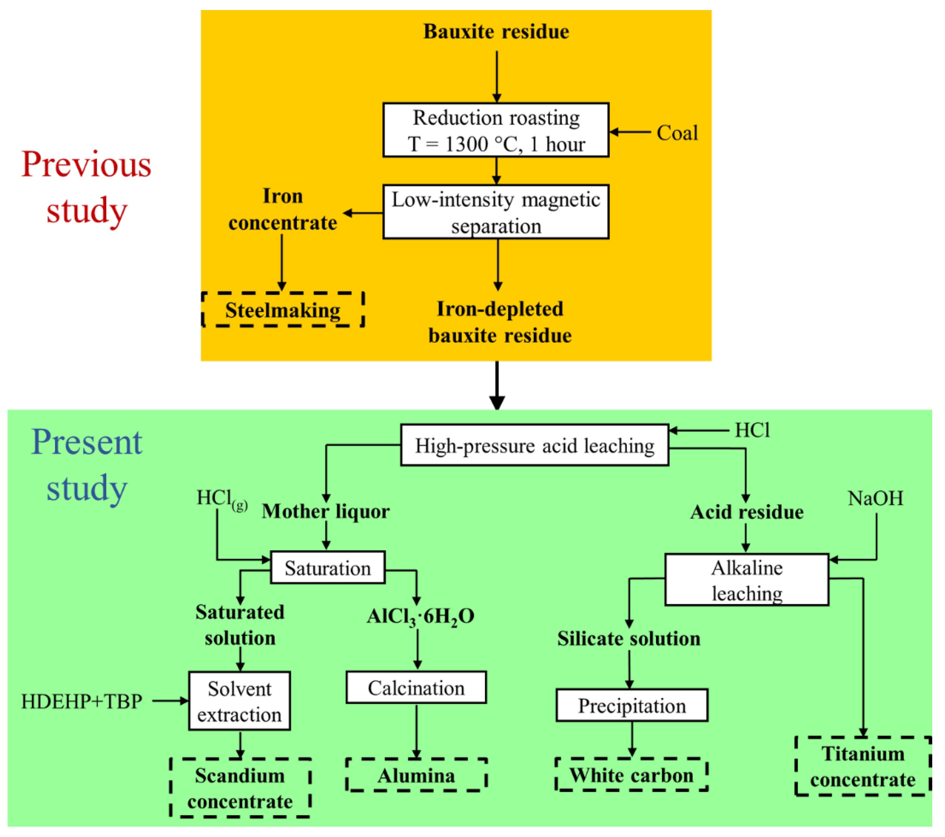
Figure 1. A conceptual flowsheet of bauxite residue treatment in the present and previous studies.
Crystals 12 01578 g001
Figure 2. XRD pattern of the IDBR sample.
Crystals 12 01578 g002
Figure 3. The effect of leaching temperature on the XRD patterns of the IDBR high-pressure leaching residues by 10% HCl at L/S ratio = 11/1 for 0 (a) and 15 min (b); P—perovskite (CaTiO3); A—anatase (TiO2); I—spinel (MgAl2O4); S—sulfur (S8); C—graphite (C); N—halite (NaCl).
Crystals 12 01578 g003
Figure 4. The effect of leaching temperature on the recovery degree of calcium without the holding (0 min) and during 15 min of high-pressure leaching of the IDBR by 10% HCl at L/S ratio = 11/1.
Crystals 12 01578 g004
Figure 5. The XRD patterns of the accumulated residue after the high-pressure leaching of IDBR by 10% HCl at 210 °C at an L/S ratio of 11/1 for 15 min of the holding.
Crystals 12 01578 g005
Figure 6. The XRD pattern of ACH precipitated from the mother liquor by its saturation using gaseous HCl.
Crystals 12 01578 g006
Figure 7. TG-DTA plots of ACH precipitated from the mother liquor.
Crystals 12 01578 g007
Figure 8. The XRD patterns of Al2O3 were prepared using the calcination of the ACH sample at 800 °C for 60 min in the air without additional treatment (a), with subsequent water washing at 70 °C for 30 min (b), as well as with subsequent water washing at 25 °C for 15 min and the repeated calcination at 800 °C for 60 min (c); N—halite (NaCl), G—γ-Al2O3.
Crystals 12 01578 g008
Figure 9. SEM image of the purer Al2O3 sample after water washing and calcination at 800 °C (a), the EDX spectrum for the image region (b), as well as aluminum (c) and oxygen (d) distribution maps.
Crystals 12 01578 g009aCrystals 12 01578 g009b
Figure 10. The recovery degree of elements from the saturated mother liquor into strip product, washing acid, and raffinate in experiments 1 (a), 2 (b), and 3 (c).
Crystals 12 01578 g010
Figure 11. The XRD patterns of scandium concentrate obtained from exps. 2 (a) and 3 (b).
Crystals 12 01578 g011
Figure 12. The flowsheet of the scandium recovery process after the precipitation of ACH from the mother liquor of high-pressure acid leaching of IDBR.
Crystals 12 01578 g012
Figure 13. The XRD patterns of the titanium concentrate after the alkaline leaching of the acid residue.
Crystals 12 01578 g013
Figure 14. SEM image of the titanium concentrate (a) and distribution maps of magnesium (b), silicon (c), calcium (d), titanium (e), aluminum (f), and iron (g).
Crystals 12 01578 g014
Figure 15. The XRD patterns of white carbon precipitated from silicate solution precipitation using 20% HCl before (a) and after (b) following water washing.
Crystals 12 01578 g015
Figure 16. SEM images of white carbon without (a) and after water washing (b).
Crystals 12 01578 g016
Figure 17. The laboratory-scale flowsheet with marked recovery degrees of Sc, Al, Ti, and Si into the main intermediate and final products from the IDBR sample. Mass or volume and yield (in green) are also indicated.
Crystals 12 01578 g017
Table 1. Chemical composition of the IDBR sample, wt.%.
SampleAlSiCaTiFeMgMnNaPSCrSc
Bauxite residue6.764.076.622.834.80.40.22.450.380.480.080.014
IDBR15.0210.0614.776.204.340.910.705.120.220.910.180.032
Table 2. Stages of solvent extraction experiments for scandium recovery.
StageExp. 1Exp. 2Exp. 3
Preparation of organic phase5 mL 10% HDEHP + 1 mL 2% TBP + 45 mL kerosene
Treatment of organic phase10 mL of organic phase
+10 mL 0.5 M H2SO4+5 mL 2.5 M HCl
Preparation of aqueous phase20 mL of diluted solution30 mL of diluted solution15 mL of diluted solution
+ 20 mL 0.77 g/L Sc
+10 mL 0.77 g/L Sc
Treatment of the aqueous phase30 mL of the aqueous phase40 mL of the aqueous phase35 mL of the aqueous phase
+0.05 g Fe
Solvent extraction (10 min)25 mL of aqueous phase
+ 5 mL 3% H2O2
30 mL of aqueous phase + 2 mL 3% H2O2
+10 mL of organic phase
Acid washing of loaded organic phase (10 min)1) 10 mL of loaded organic phase + 10 mL 1 M HCl;
2) 10 mL of loaded organic phase + 10 mL water.
1) 10 mL of loaded organic phase + 5 mL 5 M HCl;
2) 10 mL of loaded organic phase + 10 mL water.
Stripping10 mL 2 M NaOH
t1 (stirring) = 5 min;
t2 (stand-by) = 10 min.
5 mL 25 M HF +
5 mL 0.5 M H2SO4
t1 (stirring) = 10 min;
t2 (layering) = 20 min.
1) 10 mL 10% H2C2O4 +
2% (NH4)2C2O4
t1 (stirring) = 5 min;
2) 2 mL 25 M HF +
8 mL 0.5 M H2SO4
t2 (stirring) = 10 min
Dissolution5 M H2SO45 M H2SO4
Precipitation of Sc(OH)3/Sc2(C2O4)310% H2C2O4 additionNH4OH additionfiltration without any reagent addition
Calcination in airno precipitate500 °C1000 °C
Table 3. Chemical composition of the residue of the high-pressure leaching of the IDBR sample by 10% HCl, wt. %.
AlSiCaTiFeMgMnNaClPSCNiCrSrYZrSc
6.3121.61.9112.23.721.240.270.572.370.410.252.70.100.340.100.030.570.014
Table 4. Chemical composition of mother liquor from HCl leaching of IDBR, mg/L.
AlFeSiNaCaTiScZrCrMgVZnMn
10,800206813.339201567035.814.80.143740147.234.8302
Table 5. Chemical composition of ACH precipitated from the mother liquor by saturation using gaseous HCl, wt.%.
AlMgSiCaScTiVCrMnFeZnSr
10.70.040.90.120.0040.040.0070.290.010.10.0040.004
Table 6. Comparison with standard requirements of Al2O3 obtained by calcination of ACH at 800 °C for 60 min followed by water leaching and the same calcination, wt.%.
ElementsObtained Al2O3Al2O3 According to UC RUSAL Standard [58]
Al2O393.0>98.5
Na2O0.19<0.1–0.2
MgO0.23<0.005
SiO20.86<0.01
CaO0.35<0.05
TiO20.043<0.001
V2O50.021<0.001
Cr2O31.08<0.001
MnO20.047<0.001
Fe2O30.57<0.01
ZnO0.012<0.005
Specific surface area, m2/g50.670–80
Table 7. The chemical composition of the prepared solutions for Sc solvent extraction, mg/L.
ElementCaMgAlScTiVCrMnFeSrYZr
Exp. 176434.76003166.72.82.124.737543.250.01
Exp. 281837.16432627.12.92.226.540246.350.01
Exp. 349122.33864914.31.81.315.924127.83.20.01
Table 8. Chemical composition of the titanium concentrate prepared by leaching of the acid residue, wt.%.
AlSiCaTiFeMgMnNaPSCNiCrSrYZrSc
8.014.433.5624.94.422.760.370.280.400.404.90.200.850.140.050.750.018
Table 9. Comparison with standard requirements of SiO2 obtained by precipitation from silicate solution followed by water washing and drying at 250 °C, wt.%.
AttributeObtained SiO2SiO2 According to Russian State Standard GOST 18307–78
BS–30 GradeBS–50 Grade
SiO277>85>76
CaO + MgO0.18<0.5<7
Na2O0.04<0.9<1.8
Fe2O30.16not rated<0.03
Al2O31.51not rated<0.10
Moisture, wt.%3.35<6.5<6.0
pH of aqueous extract108–109–10.5
Loss of ignition, wt.%5.064.5–7.57–10
Specific surface area, m2/g50.925–4535–55
Table 10. Enrichment ratios of the obtained valuable products.
ProductScandium
Concentrate
AluminaTitanium
Concentrate
White Carbon
ElementScAlTiSi
Content, wt.%9449.2324.9236
KIDBR30323.284.023.58
KBR67147.288.908.85
Table 11. The main differences between Orbite and the developed process in this study to treat bauxite residue.
AttributeThe Orbite Process [65]The Developed Process
Iron removal stageLeaching, hydrolysis, and precipitationCarbothermic reduction and magnetic separation
Number of acid leaching stagesTwo One
Acid concentration and consumptionStrong acid and high consumptionDilute acid and low consumption
Ti and Si separationHydrochloric acid leachingAlkaline leaching
Production of white carbon NoYes
Publisher’s Note: MDPI stays neutral with regard to jurisdictional claims in published maps and institutional affiliations.