
A Molten Salt Electrochemical Process for the Preparation of Cost-Effective p-Block (Coating) Materials


Abstract
1. Introduction
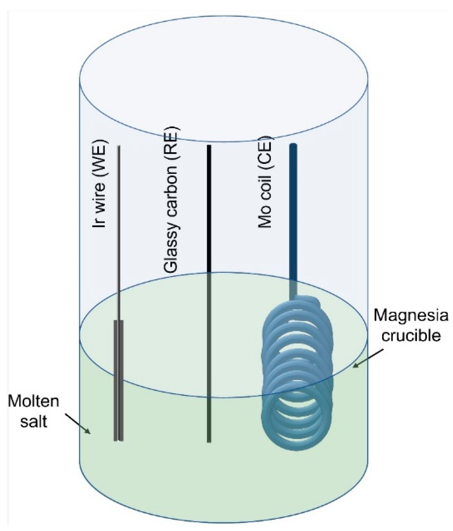
2. Experimental
3. Results and Discussion
3.1. Cyclic Voltammetric Measurements
3.2. Galvanostatic Experiment
3.3. Inductively Coupled Plasma–Mass Spectrometric (ICP-MS) Analysis of the Deposit
3.4. XRD Patterns of the Deposits
- Unlike platinum, the mechanical integrity of iridium was not observed to have been adversely impacted. Iridium and tellurium did not form any brittle telluride phases. These studies have clearly indicated the superior features of iridium over platinum.
- The tellurium deposit was observed to be highly pure.
- The tellurium coating on iridium was observed to be smooth, thick and adherent. The coating did not undergo any spallation and/or form cracks even after repeated washing.
- Iridium can be used as a metal substrate to form tellurium-coated components for solar energy devices.
4. Conclusions
Author Contributions
Funding
Institutional Review Board Statement
Informed Consent Statement
Data Availability Statement
Acknowledgments
Conflicts of Interest
References
- Smith, Y.R.; Nagel, J.R.; Rajamani, R.K. Electrodynamic Eddy Current Separation of End-of-Life PV Materials. In Energy Technology 2017; The Minerals, Metals & Materials Series; Zhang, L., Ed.; Springer: Berlin/Heidelberg, Germany, 2017; pp. 379–386. [Google Scholar]
- Bogust, P.; Smith, Y.R. Physical separation and beneficiation of end-of-life photovoltaic panel materials: Utilizing tem-perature swings and particle shape. JOM 2020, 72, 2615–2623. [Google Scholar] [CrossRef]
- Bruckman, L.S. Transformative Opportunities from Data Science and Big Data Analytics: Applied to Photovoltaics. Electrochem. Soc. Interface 2019, 28, 57–61. [Google Scholar] [CrossRef]
- Bartlett, P.N.; Cook, D.; de Groot, C.H.; Hector, A.L.; Huang, R.; Jolleys, A.; Kissling, G.P.; Levason, W.; Pearce, S.J.; Reid, G. Non-aqueous electrodeposition of p-block metals and metalloids from halometallate salts. RSC Adv. 2013, 3, 15645–15654. [Google Scholar] [CrossRef]
- Kowalik, R.; Kutyła, D.; Mech, K.; Tokarski, T.; Zabinski, P. Electrowinning Of Tellurium From Acidic Solutions. Arch. Met. Mater. 2015, 60, 591–596. [Google Scholar] [CrossRef]
- Redlinger, M.; Eggert, R.; Woodhouse, M. Evaluating the availability of gallium, indium, and tellurium from recy-cled photovoltaic modules. Sol. Energy Mater. Sol. Cells 2015, 138, 58–71. [Google Scholar] [CrossRef]
- Sen, S.; Bhatta, U.M.; Kumar, V.; Muthe, K.P.; Bhattacharya, S.; Gupta, S.K.; Yakhmi, J.V. Synthesis of Tellurium Nanostructures by Physical Vapor Deposition and Their Growth Mechanism. Cryst. Growth Des. 2008, 8, 238–242. [Google Scholar] [CrossRef]
- Ma, Y.-T.; Gong, Z.-Q.; Xu, W.-H.; Huang, J. Structural and optical properties of tellurium films obtained by chemical vapor deposition(CVD). Tran. Nonferr. Met. Soc. China 2006, 16, 693–699. [Google Scholar] [CrossRef]
- Kowalik, R.; Kutyła, D.; Mech, K.; Żabiński, P. Analysis of tellurium thin films electrodeposition from acidic citric bath. Appl. Surf. Sci. 2016, 388, 817–824. [Google Scholar] [CrossRef]
- Johnson, R.W.; Hultqvist, A.; Bent, S.F. A brief review of atomic layer deposition: From fundamentals to applications. Mater. Today 2014, 17, 236–246. [Google Scholar] [CrossRef]
- Ito, S.; Kitagawa, N.; Shibahara, T.; Nishino, H. Electrochemical Deposition of Te and Se on Flat TiO2for Solar Cell Application. Int. J. Photoenergy 2014, 2014, 5. [Google Scholar] [CrossRef]
- Ebe, H.; Ueda, M.; Ohtsuka, T. Electrodeposition of Sb, Bi, Te, and their Alloys in AlCl3–NaCl–KCl Molten Salt. Electrochim. Acta 2007, 53, 100–105. [Google Scholar] [CrossRef]
- Fellner, P.; Chrenkova-Paucirova, M.; Matiasovsky, K. Electrolytic Aluminum Plating in Molten Salt Mixtures Based on A1C13 I: Influence of the Addition of Tetra methyl ammonium chloride. Surf. Technol. 1981, 14, 101–108. [Google Scholar] [CrossRef]
- Paucirova, M.; Matiasovsky, K. Electrolytic Aluminum-Plating in Fused Salts Based on Chlorides. Electrodepos. Surf. Treat. 1975, 3, 121–128. [Google Scholar] [CrossRef]
- Tripathy, P.K.; Wurth, L.A.; Dufek, E.J.; Gutknecht, T.Y.; Gese, N.J.; Hahn, P.A.; Frank, S.M.; Fredrickson, G.L.; Herring, J.S. Aluminum electroplating on steel from a fused bromide electrolyte. Surf. Coat. Technol. 2014, 258, 652–663. [Google Scholar] [CrossRef][Green Version]
- Wu, G.; Li, N.; Zhou, D.; Mitsuo, K. Electrodeposited Co–Ni–Al2O3 composite coatings. Surf. Coat. Technol. 2004, 176, 157–164. [Google Scholar] [CrossRef]
- Gu, Y.; Liu, J.; Qu, S.; Deng, Y.; Han, X.; Hu, W.; Zhong, C. Electrodeposition of alloys and compounds from high-temperature molten salts. J. Alloys Compd. 2017, 690, 228–238. [Google Scholar] [CrossRef]
- Herrmann, S.D.; Tripathy, P.K.; Frank, S.M.; King, J.A. Comparative Study of Monolithic Platinum and Iridium as Oxy-gen-evolving Anodes during the Electrolytic Reduction of Uranium Oxide in a Molten LiCl-Li2O Electrolyte. J. Appl. Electrochem. 2019, 49, 379–388. [Google Scholar] [CrossRef]
- H.S.C. Chemistry, Ver. 7; Outotec: Pori, Finland, 2015.


| Element | Amount (wt.%) |
|---|---|
| Li | 75.8 |
| Te | 24.2 |
| Ir | 0.1 |
Publisher’s Note: MDPI stays neutral with regard to jurisdictional claims in published maps and institutional affiliations. |
© 2022 by the authors. Licensee MDPI, Basel, Switzerland. This article is an open access article distributed under the terms and conditions of the Creative Commons Attribution (CC BY) license (https://creativecommons.org/licenses/by/4.0/).
Share and Cite
Tripathy, P.K.; Mondal, K. A Molten Salt Electrochemical Process for the Preparation of Cost-Effective p-Block (Coating) Materials. Crystals 2022, 12, 385. https://doi.org/10.3390/cryst12030385
Tripathy PK, Mondal K. A Molten Salt Electrochemical Process for the Preparation of Cost-Effective p-Block (Coating) Materials. Crystals. 2022; 12(3):385. https://doi.org/10.3390/cryst12030385
Chicago/Turabian StyleTripathy, Prabhat Kumar, and Kunal Mondal. 2022. "A Molten Salt Electrochemical Process for the Preparation of Cost-Effective p-Block (Coating) Materials" Crystals 12, no. 3: 385. https://doi.org/10.3390/cryst12030385
APA StyleTripathy, P. K., & Mondal, K. (2022). A Molten Salt Electrochemical Process for the Preparation of Cost-Effective p-Block (Coating) Materials. Crystals, 12(3), 385. https://doi.org/10.3390/cryst12030385