Abstract
Fine-pitch backlight technology is rapidly evolving along with display technology, and chips are increasingly designed for direct integration with modules. This study used a distributed Bragg reflector (DBR) for mini light-emitting diode (mini-LED) backlights with high dynamic contrast and developed a digital twin design by using a light-emitting diode (LED) and a distributed Bragg reflector (DBR).
1. Introduction
Light-emitting diodes (LEDs) have received considerable attention because of the versatility of their application in optoelectronics [1,2]. Several research facilities and businesses have encouraged the development of fine-pitch technology in the display industry [3,4]. Micro-LEDs and mini-LEDs have received considerable attention in the display industry due to their small size, fast response time, high brightness, and high contrast [5]. Mini-LEDs are extensively used as liquid crystal display backlights because of their excellent dynamic range, power efficiency, and quantum yield. As a result, various companies in the display industry have adopted mini-LED technology [6,7].
High dynamic range (HDR) is a key feature for next-generation displays, and an HDR display should have a high contrast ratio (CR; >105:1) to expose high-resolution images simultaneously in low- and high-brightness regions. A system can provide HDR if it has high peak brightness and an adequate dark state [8,9]. The luminance of the bright state should be higher than 1000 nits, whereas the luminance of the dark state should be lower than 0.01 nits [10]. Mini-LEDs are a promising candidate for backlight applications that satisfy these criteria. Mini-LEDs have larger chips (100–500 µm) and are easier to fabricate than micro-LEDs. In addition, mini-LED backlights can offer more than 10,000 local dimming zones at high brightness (>1000 nits), ensuring excellent HDR performance. To achieve the finest HDR for backlight applications, several researchers have attempted to produce superior light pattern uniformity and minimize cross talk between adjacent LED pixels. Several technologies have been developed since the 1990s to increase the quality of display light patterns. Lin et al. introduced a design and simulation model of scattering netted dots on side-incident light guide plates that exhibited 93% illumination uniformity for LED backlight applications [11]. Huang et al. demonstrated an ultrathin mini-LED with high light extraction efficiency involving a freeform-designed chip-scale package that provided a light extraction efficiency of up to 96% [12]. For all display solutions, a standard factor called “vision uniformity” is used to examine the quality of light patterns. We performed Fourier fusion analysis on a computer vision technology to measure light pattern quality [13,14].
A distributed Bragg reflector (DBR) is a high-reflectivity optical mirror consisting of multiple pairs of distinct dielectric layers with different refractive indices in an alternating order [15]. Its design is adaptable, and the appropriate stop-band can be determined by changing the thicknesses of the dielectric layers [16]. The DBR structure can be used to produce designs for a variety of applications, such as the mirror structure in a fine-pitch LED array for generating an excellent light pattern on a micro-scale LED array [17]. Two methods are widely used: placing mirror structures atop gallium nitride (GaN)-based chips to improve light quality when the pitch of a mini-LED is sufficiently fine [16,18,19] and introducing chip-scale packaging with a freeform surface to optimize the light pattern when a mini-LED pitch is sufficiently large [20,21]. Ultrafine pitch displays are the ultimate goal of the advanced display technology roadmap, with the mirror structure being the most critical element. DBRs with a multilayer thin film structure provide a solution superior to traditional mirror structures owing to their high flexibility in terms of the reflectivity of specific wavelengths [22].
We explored a DBR technology for mini-LED backlights with high dynamic contrast and developed a digital twin design by tuning DBR parameters and using computer-aided engineering (CAE) tools. The DBR structure was created by depositing alternating thin multilayers of TiO2 and SiO2 atop the mini-LED chip. We compared the DBR and DBR-free architectures, which had forwarding reflectances of 80% and 95%, respectively. The results revealed that the pattern quality of a single image and module improved considerably under a forward reflectance of 80%.
2. Digital Twin and Modeling
2.1. Model Architecture and Key Parameters
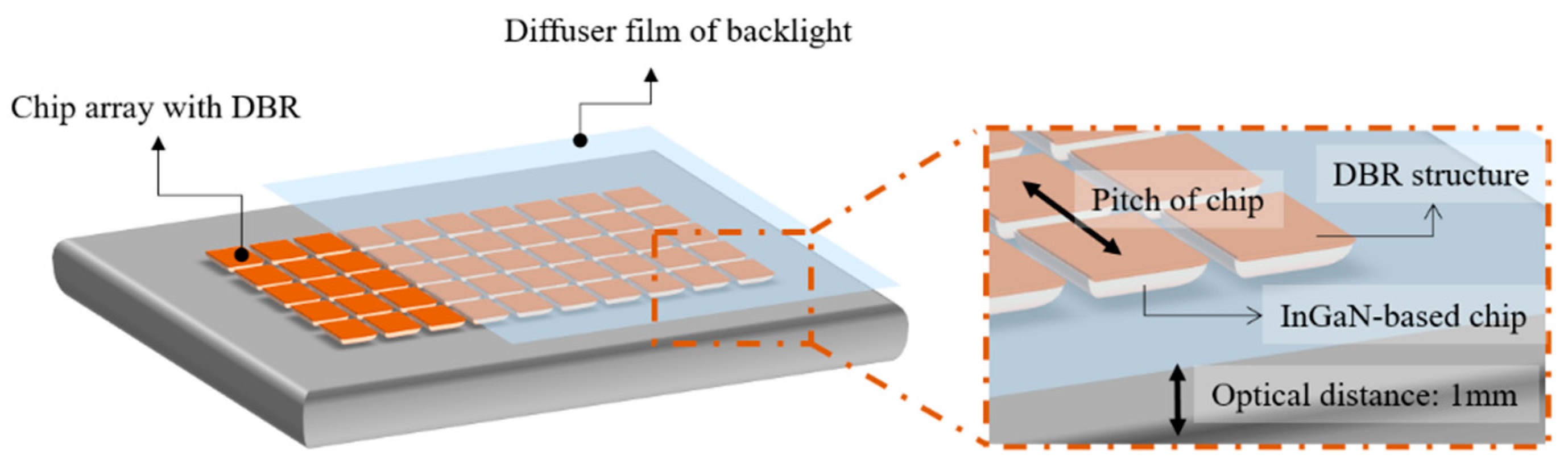
This study employed CAE to determine the optimal design for the DBR and LED array to improve the pattern quality of the mini-LED backlight. The proposed mini-LED module structure consisted of an LED array with a DBR structure and backlight diffuser (Figure 1). To generate a set of DBR structures, thin alternating layers of TiO2 and SiO2 were deposited on the outermost glass layer atop the original P–N structure of the single-model LED.
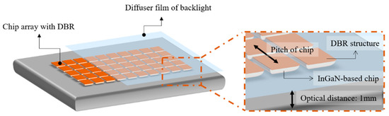
Figure 1.
Mini light-emitting diode backlight with distributed Bragg reflector (DBR).
The indium GaN (InGaN)-based chip array used in the model had an emission peak wavelength of 445 nm. The InGaN-based chip array was bonded to the opaque substrate, and the DBR structure with various reflectivities was placed atop the InGaN-based chip array (Figure 1). The optical detector, with dimensions of 30 mm × 30 mm, was placed in the center of the chip array at an optical distance of 1 mm from the substrate. Table 1 lists the parameters for the mini-LED backlight design with the DBR.

Table 1.
Model parameters.
2.2. Modeling Flow
This study used the Lighttools software and application programming interface (LTAPI) to manipulate parameters and their effects on the design. Figure 2a presents the design process. First, the LTAPI was used to create parameter commands for the mini-LED DBR model, and the parameters were used to create an initial set of mini-LED light source arrays and an optical detector. Then, the CAE software was used to generate a beam-tracking model that simulated the direction of the LED light beam as it passed through the DBR and reached the light-receiving plane; this was followed by the determination of the light intensity and beam vector for each position. Because this parameter was issued in batch instructions, we used the LTAPI to clear the previous calculation model and issue the next set of parameter commands once the results of the initial parameter settings were acquired; the process was then repeated.
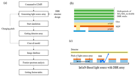
Figure 2.
(a) Modeling flow. (b) Single light source with distributed Bragg reflector (DBR) modeling. (c) Light source array modeling.
For the initial model, we adapted the flip chip-type InGaN-based chip, which had a DBR structure on the top glass and a light source in the multiple quantum well (MQW) layer (Figure 2b). Figure 2c presents the pitch of the InGaN-based array and DBR properties, which are the key parameters for improving light pattern quality. This study used MATLAB and the LTAPI to develop an automatically optimizing process. MATLAB uses the LTAPI to control a model and acquire results from various parameter settings. The quality of the light pattern was analyzed using computer vision with a simulation algorithm (Algorithm 1) to obtain a fusion index.
| Algorithm 1: Algorithm to obtain fusion index. | |
| 1 | Function main_algorithn (initial model path) |
| 2 | { |
| 3 | Import LTAPI as lt |
| 4 | lt.open(“initial model path”); |
| 5 | set detector_size = 30; |
| 6 | set LED_number = N; |
| 7 | setimg as the detector data from lighttools modeling result; |
| 8 | for N = 5:1:12 |
| 9 | pitch = detector_size/(N − 1); |
| 10 | lt.set(pitch); |
| 11 | for DBR = [80 95] |
| 12 | lt.set(DBR); |
| 13 | lt.command(“run all ray tracing” ); |
| 14 | img = lt.command(“obtain detector data” ); |
| 15 | end |
| 16 | save(img) |
| 17 | img_f = FFT (img)//Fast Fourier Transform |
| 18 | fusion_index = fusion(img_f) |
| 19 | end |
| 20 | return fusion_index; |
| 21 | } |
| 22 | |
| 23 | Function fusion(image) |
| 24 | { |
| 25 | S = sum(image); |
| 26 | K = 1/S; |
| 27 | return K |
| 28 | } |
2.3. Fourier Spectrum Analysis and Fusion Index
In the field of digital signal processing, the Fourier transform can convert data from the time domain waveform to the frequency domain. That is, the Fourier transform can decompose the signal into basic combinations, which has a large number of applications in many fields such as modern physics and engineering. In this study, we used the characteristics of the Fourier transform to separate the high-frequency and low-frequency regions to analyze the sharp features of the image. A discrete version of the quaternion Fourier transform can be used to illustrate its application to color images [23,24], and the quaternion Fourier transform can be expressed using the following equation [25]:
where M and N represent the image pixel size and m and u represent the image pixel index. Functions F and f indicate the Fourier image and original image matrix, respectively. After the Fourier transforms, on the basis of computer vision principles [26], the clarity index S can be calculated by integrating the Fourier element F[u,v] as follows:
where U represents the amount of element u and V represents the amount of element v.
Finally, after the reciprocal of S is taken in (2), the fusion index K can be defined using the following equation:
Our main purpose was to reduce the sharpness ratio of the image and improve the pattern quality through the DBR structure. We noticed that when the parameter S was larger, there were more high-frequency details, and the overall image had more sharp elements. Finally, we took the reciprocal of S to represent the ability to reduce the sharpness of the image with the DBR structure.
3. Results
3.1. Single Chip
The multilayer DBR structure can be used to alter reflectance spectra, and its reflectivity can be changed for incident light at various angles. The multilayer TiO2–SiO2 films were stacked to generate DBR structures with varying reflectance (Figure 3a). When the incident angle was 20°, the reflective layer of the TiO2–SiO2 DBR structure had destructive interference, resulting in lower reflectivity. However, when the angle of incidence was greater than 30°, the angle of incidence exceeded the total reflection angle, with reflectance reaching 100%. These results indicate that the DBR structure affects energy reflection and penetration at small angles.
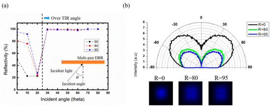
Figure 3.
Single chip with distributed Bragg reflector (DBR). (a) Reflectance. (b) Angular distribution and singular-image pattern.
The DBR structure was placed on the InGaN-based chip (Figure 2b). When R = 0%, no DBR was present. When R = 80% and 95%, the DBR structures with 80% and 95% forward reflectivity were used on the InGaN-based chips (Figure 3b). Without the DBR, the total energy of the light field distribution was higher, but the central energy was higher in the far-field pattern (Figure 3b). As a result, the single-chip light source image appeared as a visible bright spot, and the InGaN-based chip array readily generated a bright spot structure. The light field distribution at R = 80% and 95% decreased the central energy considerably, indicating the efficient suppression of the bright spot structure. However, dark spots were observed in the single-chip light source image at R = 95%, indicating that this structure is not ideal for an InGaN-based chip array because it tends to produce dark spots; R = 80% is a more suitable structure for single-chip images because it does not produce bright or dark spots.
3.2. Results of Array Modeling
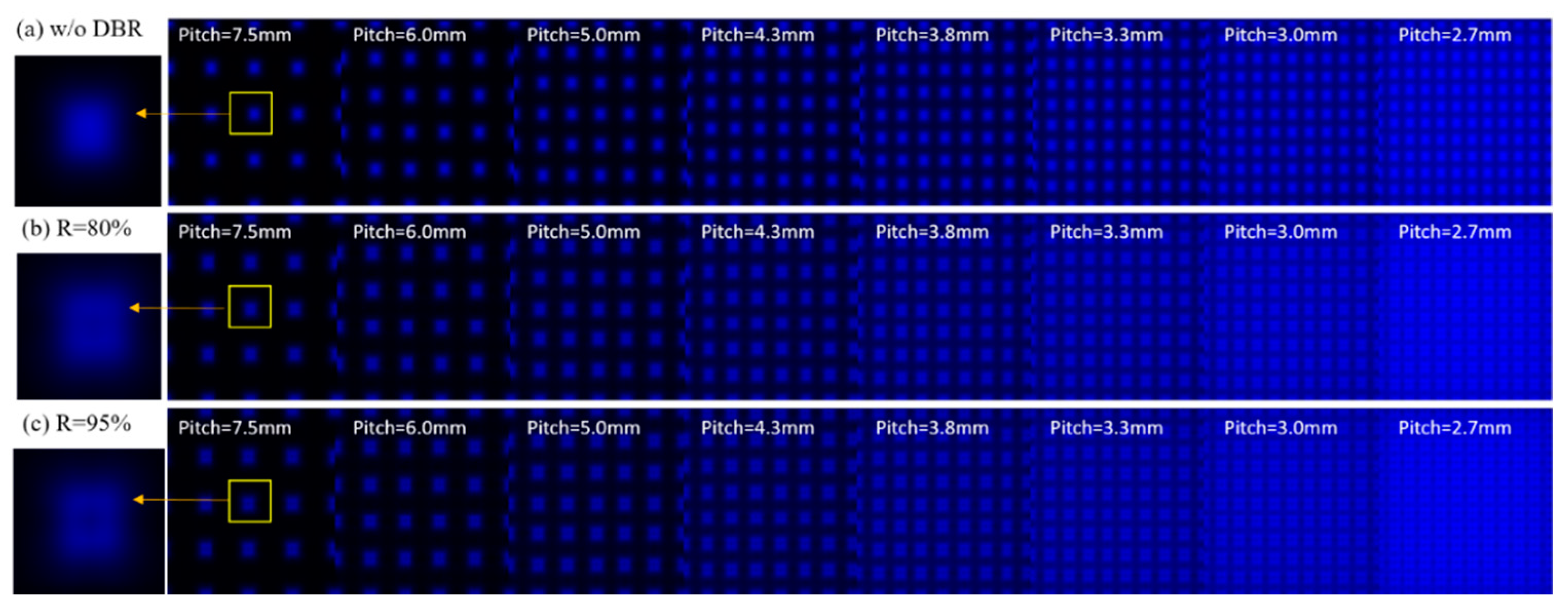
The results indicate that the DBR structure can improve the pattern quality of a unit light source considerably. However, because the advanced display’s backlight module consisted of an InGaN-based chip array, the factors that affected the visual effect and pattern quality of the unit light source differed. The cross talk effect between chips and the light spot overlap effect affected the quality of the projected flat light source after splicing. Therefore, we analyzed the number of chips in the 30 mm × 30 mm detection plane to accommodate different numbers (Figure 4). We analyzed images of 5–12 chips spaced 7.5, 6, 5, 4.3, 3.8, 3.3, 3, and 2.7 mm apart. The analysis was performed for the arrays without the DBR structure and with a DBR forward reflectivity of 80% or 95%. When the number of chips was low, the distance between the wafers was large, resulting in dark bands (Figure 4). When the pitch was <3.3 mm, the light pattern superimposed on the chips was highly visible in the image. In terms of the quality of the three architectures with a pitch of 7.5 mm, the larger pitch caused less interference between chips, and the image quality of the single wafer was the key factor that affected quality. The InGaN-based chip array with the DBR structure noticeably optimized the chip pitch, which can be observed in the photos of the three DBR structures with a pitch of 2.7 mm.

Figure 4.
Mini light-emitting diode module (a) without and (b,c) with the DBR.
Because a high-quality backlight module design is able to form a uniform energy distribution plane, neither traditional multipoint uniformity analysis [27] nor scanning uniformity [28] analysis can quantify an image entirely. We introduced a Fourier transform to compute the periodic arrangement of the InGaN-based chip array image and to obtain the Fourier image (Figure 5). In the Fourier image, the bright lines represent the intensity of each period; if the original image has highly detailed patterns, the Fourier image will have numerous textures and dots [29]. Furthermore, the Fourier image has the following characteristics: (a.) A small area near the center of the graph represents the low-frequency feature. (b.) The surrounding area represents the high-frequency feature. This means that if the overall image has more apparent bright-line texture and dots, it has more obvious high-frequency features, which means that the original image has more obvious sharp edges, resulting in an image with a lower fusion-index value [30,31]. Figure 5 presents two types of Fourier spectrum. The first is where the pitch is 5 mm or more; less spot coverage between chips was observed, indicating a discrete periodic distribution and spot details. The second is where the pitch is below 4.3 mm; the gap area between the chips began to exhibit superimposed light spots, blurring the edges and decreasing light spots considerably compared with the large pitch image.
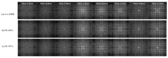
Figure 5.
Fourier image of mini light-emitting diode module (a) without (b,c) with the DBR.
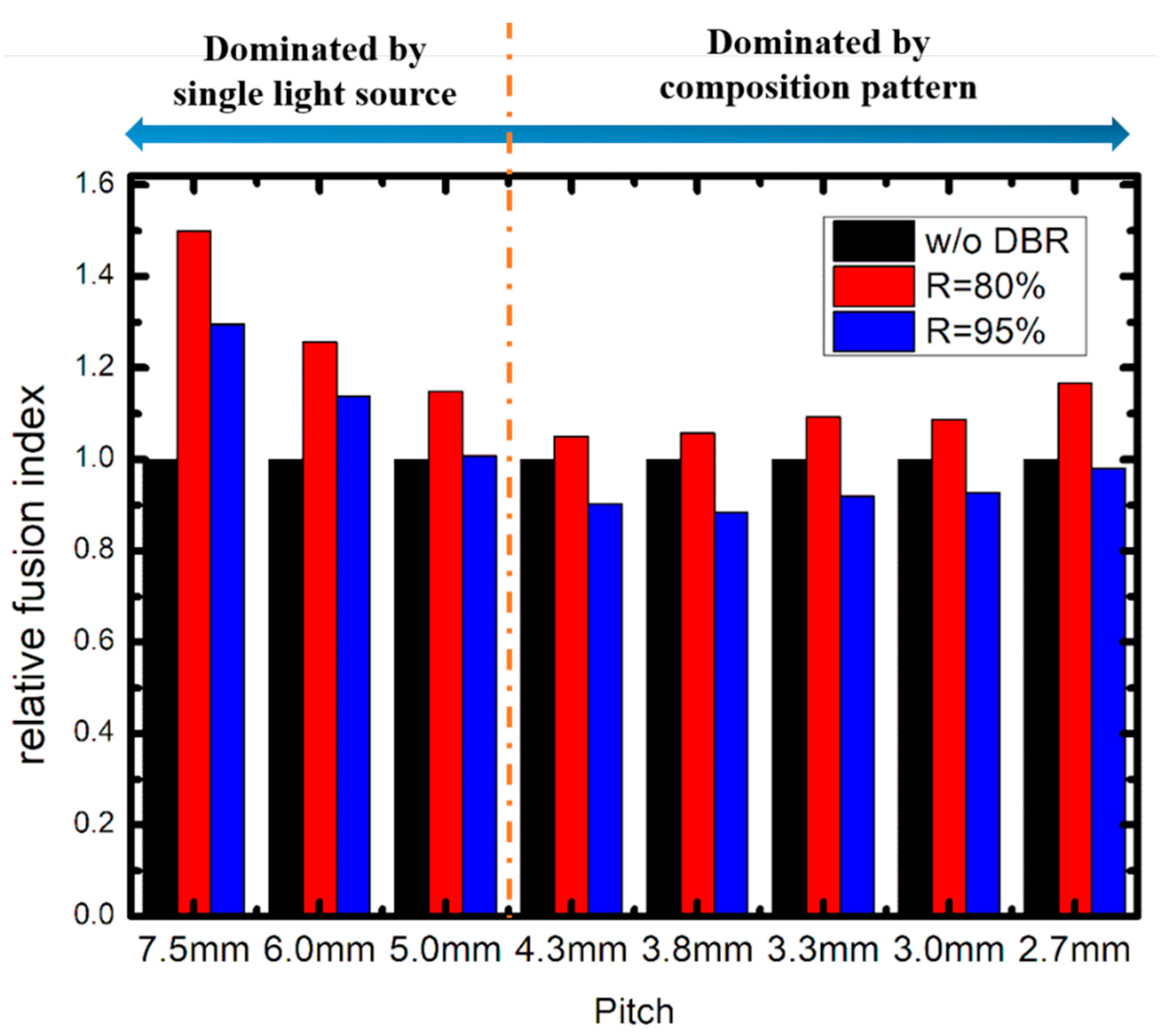
To quantify the phenomenon depicted in Figure 5, we introduced a focus algorithm in computer vision technology to calculate the fusion index, as described in Section 2.3. The fusion index values at different pitches were obtained by computing the Fourier image for analysis. The data were normalized, and the normalized data served as the basis for comparing arrays with a DBR structure with those without the DBR structure (Figure 6), and two trends were observed: (1) For a pitch larger than 5 mm, the structure with 80% and 95% DBR reflectivity exhibited a considerable improvement in pattern quality because the pattern quality of the mini-LED array was mainly affected by the single light source in designs with a larger pitch. (2) For a pitch shorter than 5 mm, the array with the DBR structure performed well in terms of edge energy superposition because of the larger luminous angle. Therefore, DBR LEDs with R = 80% improve performance.
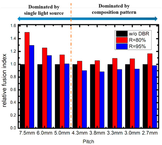
Figure 6.
Fusion index of mini light-emitting diode array with various distributed Bragg reflector (DBR) structures.
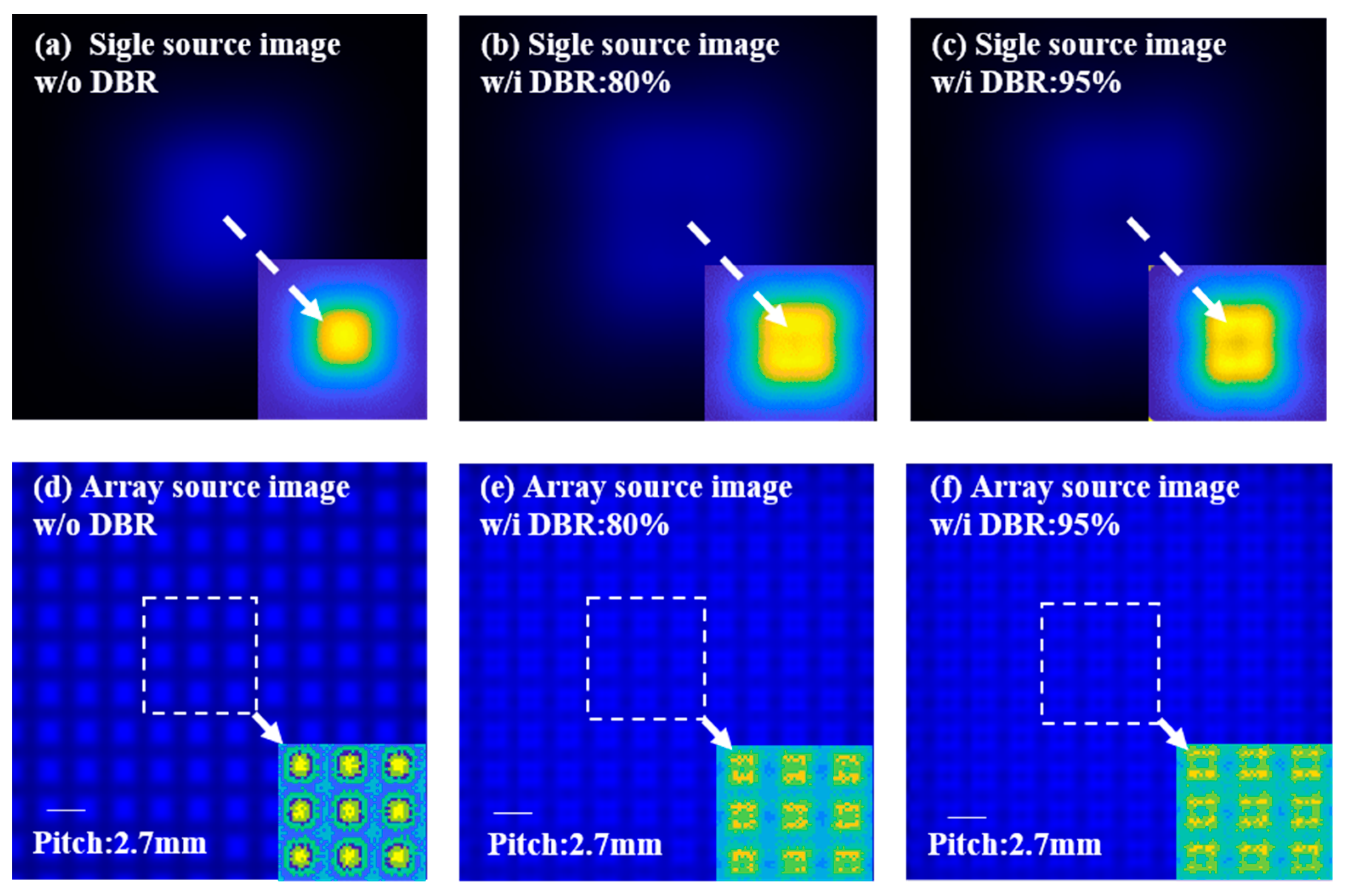
Although the DBR structure can improve picture quality, the DBR LED array at R = 95% produced lower fusion index values than the non-DBR structure did (Figure 6). We analyzed image quality with (R = 80%, 95%) and without the DBR (Figure 7a–c, respectively). The light pattern of the single light source was projected under the modular structure. The intensity analysis, depicted in Figure 7a, indicated a high energy distribution (at the center of Figure 7a). The energy distribution of the spot above the chip was uniform, but the spot area was smaller than that in Figure 7b and c. In the results for the array light source, more dark bands appeared in the chip pitch region (Figure 7d). The analysis of the array with the DBR structure (Figure 7b,c) indicated that for R = 80%, the single light source produced a more uniform energy distribution than the DBR at R = 95% did and that the DBR at R = 95% produced a notable central dark spot; this result contrasts with that shown in Figure 7e. In Figure 7f, the DBR (R = 95%) structure exhibits a superposition of light energy with a large emission angle. As a result of the superposition of energy in the periphery, the central dark spot, which was already visible in the single-chip image, became more apparent and was largely responsible for the low image quality. Therefore, an optimal design interval exists for DBR in close alignment. In this study, the DBR center reflectivity of 80% optimized the image quality of the module.

Figure 7.
Pattern quality analysis. (a–c) Single source mage quality with and without the DBR. (d–f) Array source image quality with and without the DBR.
4. Conclusions
This simulation result showed that the DBR structure would reflect a part of the light back to the substrate and continue to pass according to Snell’s law, as shown in Figure 2c. That means the DBR structure may additionally cause a halo effect and a clipping effect. In addition, the reflectivity of the substrate will also cause additional power consumption. Since the LED array forward-looking display module has high requirements for the quality of the projected light spot, we adopted the design of a high absorption substrate in the overall simulation structure. Although this design reduces part of the efficiency, it can effectively suppress the halo effects and improve the optical quality. We developed a mini-LED array with a DBR structure and digital twin design that can improve the pattern quality of mini-LED display technology; the approach involves adjusting DBR parameters and using CAE tools and computer vision technology. We compared the DBR and DBR-free architectures with a forwarding reflectance of 80% or 95%. Because of the large reflection angle of the DBR, the sample with the DBR exhibited superior performance in terms of the chip spacing of the mini-LED. The best results for the pattern quality of a single image and module were obtained when the DBR forward reflectance was 80%. The DBR structure benefits the luminous angle of a single chip, and image quality can be improved at the chip spacing. The findings also indicate the ideal structural parameters for DBR structures. The mini-LED backlight with high dynamic contrast will pave the way for innovation in advanced display technology.
Author Contributions
Conceptualization, S.-H.C., C.-H.H., C.-C.L. and H.-C.K.; data curation, C.L. and K.J.S.; formal analysis, S.-H.C. and C.-H.H.; investigation, S.-H.C. and C.-H.H.; methodology, S.-H.C., C.-H.H., C.L. and K.J.S.; project administration, C.-C.L.; supervision, H.-C.K.; writing—original draft, S.-H.C. and C.-H.H.; writing—review and editing, S.-H.C. and C.-H.H. All authors have read and agreed to the published version of the manuscript.
Funding
This research was funded by the Ministry of Science and Technology, Taiwan (MOST 110-2124-M-A49-003-; MOST 108-2221-E-009-113-MY3).
Institutional Review Board Statement
Not applicable.
Informed Consent Statement
Not applicable.
Data Availability Statement
Not applicable.
Conflicts of Interest
The authors declare no conflict of interest.
References
- Yang, Y.Z.; Chung, S.-R. High color gamut of perovskite QDs/PMMA-based white light-emitting diode. In Organic Light Emitting Materials and Devices XXII; International Society for Optics and Photonics: Bellingham, WA, USA, 2018; Volume 10736, p. 107361G. [Google Scholar]
- Chen, S.W.H.; Huang, Y.M.; Chang, Y.H.; Lin, Y.; Liou, F.J.; Hsu, Y.C.; Song, J.; Choi, J.; Chow, C.W.; Lin, C.C.; et al. High-Bandwidth Green Semipolar (20–21) InGaN/GaN Micro Light-Emitting Diodes for Visible Light Communication. ACS Photonics 2020, 7, 2228–2235. [Google Scholar] [CrossRef]
- Peng, D.; Zhang, K.; Liu, Z. Design and Fabrication of Fine-Pitch Pixelated-Addressed Micro-LED Arrays on Printed Circuit Board for Display and Communication Applications. IEEE J. Electron. Devices Soc. 2017, 5, 90–94. [Google Scholar] [CrossRef]
- Koma, N.; Tanase, K.; Yasukawa, K.; Watanabe, Y.; Karasawa, Y.; Tanaka, T.; Miyashita, S.; Atobe, M. P-75: Improved Optical Characteristics of a Front-Light System Using Fine-Pitch Patterned OLED. SID Symp. Dig. Tech. Pap. 2009, 40, 1399–1402. [Google Scholar] [CrossRef]
- Wu, T.; Sher, C.-W.; Lin, Y.; Lee, C.-F.; Liang, S.; Lu, Y.; Chen, S.-W.H.; Guo, W.; Kuo, H.-C.; Chen, Z. Mini-LED and Micro-LED: Promising Candidates for the Next Generation Display Technology. Appl. Sci. 2018, 8, 1557. [Google Scholar] [CrossRef] [Green Version]
- AU Optronics Corp. 2018. Available online: https://www.auo.com/en-global/New_Archive/detail/News_Archive_Technology_180522 (accessed on 29 March 2022).
- LEDinside, a Business Division of TrendForce Corp. 2018. Available online: https://www.ledinside.com/showreport/2018/5/display_week_2018_show_report_mini_led_backlight_business_opportunities_boost (accessed on 29 March 2022).
- Daly, S.; Kunkel, T.; Sun, X.; Farrell, S.; Crum, P. Viewer preferences for shadow, diffuse, specular, and emissive luminance limits of high dynamic range displays. SID Symp. Dig. Tech. Pap. 2013, 44, 563–566. [Google Scholar] [CrossRef]
- Zhu, R.; Sarkar, A.; Emerton, N.; Large, T. 81-3: Reproducing High Dynamic Range Contents Adaptively based on Display Specifications. SID Symp. Dig. Tech. Pap. 2017, 48, 1188–1191. [Google Scholar] [CrossRef]
- Chen, H.; Zhu, R.; Li, M.-C.; Lee, S.-L.; Wu, S.-T. Pixel-by-pixel local dimming for high-dynamic-range liquid crystal displays. Opt. Express 2017, 25, 1973–1984. [Google Scholar] [CrossRef] [Green Version]
- Lin, X.X.; Ying, X.; Xiao-feng, P. Design and Simulation of Scattering Netted Dots on Light Guide Plate of Side-incident LED Backlight. J. Guangdong Univ. Technol. 2014, 31, 95–99. [Google Scholar]
- Huang, C.H.; Kang, C.Y.; Chang, S.H.; Lin, C.H.; Lin, C.Y.; Wu, T.; Sher, C.W.; Lin, C.C.; Lee, P.T.; Kuo, H.C. Ultra-high light extraction efficiency and ultra-thin mini-LED solution by freeform surface chip scale package array. Crystals 2019, 9, 202. [Google Scholar] [CrossRef] [Green Version]
- Sieberth, T.; Wackrow, R.; Chandler, J.H. Automatic detection of blurred images in UAV image sets. ISPRS J. Photogramm. Remote Sens. 2016, 122, 1–16. [Google Scholar] [CrossRef] [Green Version]
- Narwaria, M.; Lin, W.; McLoughlin, I.V.; Emmanuel, S.; Chia, L.-T. Fourier transform based scalable image quality measure. IEEE Trans. Image Process. 2012, 21, 3364–3377. [Google Scholar] [CrossRef] [PubMed]
- Zhou, F.; Feng, J.-F.; Shi, Q.-Y. Texture feature based on local Fourier transform. In Proceedings of the 2001 International Conference on Image Processing (Cat. No.01CH37205), Thessaloniki, Greece, 7–10 October 2001; Volume 2, pp. 610–613. [Google Scholar]
- Sugawara, H.; Itaya, K.; Hatakoshi, G.I. Hybrid-type InGaAlP/GaAs distributed Bragg reflectors for InGaAlP light-emitting diodes. Jpn. J. Appl. Phys. 1994, 33, 6195–6198. [Google Scholar] [CrossRef]
- Chiou, S.W.; Lee, C.P.; Huang, C.K.; Chen, C.W. Wide angle distributed Bragg reflectors for 590 nm amber AlGaInP light-emitting diodes. J. Appl. Phys. 2000, 87, 2052–2054. [Google Scholar] [CrossRef] [Green Version]
- Lin, H.Y.; Chen, K.J.; Wang, S.W.; Lin, C.C.; Wang, K.Y.; Li, J.R.; Lee, P.T.; Shih, M.H.; Li, X.; Chen, H.M.; et al. Improvement of light quality by DBR structure in white LED. Opt. Express 2015, 23, A27–A33. [Google Scholar] [CrossRef]
- Wang, D.X.; Ferguson, I.T.; Buck, J.A.; Nicol, D. Optical design and simulation for nanoscale Distributed Bragg Reflector (DBR) for high-brightness LED. In Nanoengineering: Fabrication, Properties, Optics, and Devices III; International Society for Optics and Photonics: Bellingham, WA, USA, 2006; Volume 6327, p. 63270Q. [Google Scholar]
- Jeong, T.; Lee, H.H.; Park, S.H.; Baek, J.H.; Lee, J.K. InGaN/AlGaN ultraviolet light-emitting diode with a Ti3O5/Al2O3 distributed Bragg reflector. Jpn. J. Appl. Phys. 2008, 47, 8811. [Google Scholar] [CrossRef]
- Wang, K.; Liu, S.; Chen, F.; Qin, Z.; Liu, Z.; Luo, X. Freeform LED lens for rectangularly prescribed illumination. J. Opt. A Pure Appl. Opt. 2009, 11, 105501. [Google Scholar] [CrossRef]
- Huang, C.-H.; Chen, K.-J.; Tsai, M.-T.; Shih, M.-H.; Sun, C.-W.; Lee, W.-I.; Lin, C.-C.; Kuo, H.C. High-efficiency and low assembly-dependent chip-scale package for white light-emitting diodes. J. Photon. Energy 2015, 5, 057606. [Google Scholar] [CrossRef]
- Schubert, M.F.; Xi, J.-Q.; Kim, J.K.; Schubert, E.F. Distributed Bragg reflector consisting of high- and low-refractive-index thin film layers made of the same material. Appl. Phys. Lett. 2007, 90, 141115. [Google Scholar] [CrossRef] [Green Version]
- Sangwine, S. Fourier transforms of colour images using quaternion or hypercomplex, numbers. Electron. Lett. 1996, 32, 1979–1980. [Google Scholar] [CrossRef]
- Hamilton, W.R. Elements of Quaternions; Longmans, Green, and Company: London, UK, 1866. [Google Scholar]
- Ell, T.A.; Sangwine, S. Hypercomplex Fourier Transforms of Color Images. IEEE Trans. Image Process. 2007, 16, 22–35. [Google Scholar] [CrossRef]
- Mario, A.B.; Alvarez-Borrego, J.; Acho, L. Autofocus algorithm using one-dimensional Fourier transform and Pearson correlation. In 5th Iberoamerican Meeting on Optics and 8th Latin American Meeting on Optics, Lasers, and Their Applications; International Society for Optics and Photonics: Bellongham, WA, USA, 2004; Volume 5622, pp. 760–765. [Google Scholar]
- He, J.; Zhang, Q.; Wang, J.; Zhou, J.; Liang, H. Investigation on quantitative uniformity evaluation for directional backlight auto-stereoscopic displays. Opt. Express 2018, 26, 9398–9408. [Google Scholar] [CrossRef] [PubMed]
- Lin, C.-S.; Wu, W.-Z.; Lay, Y.-L.; Chang, M.-W. A digital image-based measurement system for a LCD backlight module. Opt. Laser Technol. 2001, 33, 499–505. [Google Scholar] [CrossRef]
- Yoo, Y. Tutorial on Fourier Theory. 17 June 2001. Available online: http://www.cs.otago.ac.nz/cosc453/student_tutorials/fourier_analysis.pdf(accessed on 15 February 2022).
- Lim, J.S. Two-Dimensional Signal and Image Processing; Prentice Hall: Englewood Cliffs, NJ, USA, 1990. [Google Scholar]


Publisher’s Note: MDPI stays neutral with regard to jurisdictional claims in published maps and institutional affiliations. |
© 2022 by the authors. Licensee MDPI, Basel, Switzerland. This article is an open access article distributed under the terms and conditions of the Creative Commons Attribution (CC BY) license (https://creativecommons.org/licenses/by/4.0/).