Article

Enhanced THz Transmission by Bull’s Eye Structure Integrated with a Concentric Gold Hemisphere

1
School of Microelectronics, Shandong University, Jinan 250100, China
2
Engineering Research Center for Semiconductor Integrated Technology, Institute of Semiconductors, Chinese Academy of Sciences, Beijing 100083, China
*
Author to whom correspondence should be addressed.
Crystals 2022, 12(9), 1210; https://doi.org/10.3390/cryst12091210
Submission received: 7 August 2022 / Revised: 24 August 2022 / Accepted: 25 August 2022 / Published: 27 August 2022
(This article belongs to the Special Issue Terahertz Metamaterials and Active Modulation)

Abstract

:
In this work, a hemispheric gold particle is introduced to the conventional bull’s eye structure that enhances extraordinary optical transmission in the terahertz region. Transmission enhancement is a result of the coupling of surface plasmon polaritons generated by periodic grooves and localized surface plasmon resonances generated by the hemisphere particle. The maximum normalized-to-area transmission peak reaches 556 for the hemisphere-in-hole bull’s eye structure, which is significantly higher than conventional bull’s eye structure. Such a transmission property is insensitive to polarization direction. The physical mechanisms are thoroughly analyzed by geometric parameter optimization and electromagnetic simulations. The modified structure can reduce the number of grooves in need, thereby reducing the device area. This novel design can be instructive for future improvement of bull’s eye applications.

1. Introduction

Concentrating a large area of optical energy within subwavelength aperture has stimulated a broad interest in bull’s eye structure [1,2,3,4,5,6] that can be used for high-speed photodetector [7,8,9], plasmonic focusing [10], molecular sensing [11,12], and enhanced optical transmission (EOT) [13]. The periodic grooves act as antennas to enhance light-matter interaction on metal surface, achieving EOT through the central hole [14]. According to Degiron [15], the optical transmission mechanism of bull’s eye structure can be divided into three processes: coupling in, transmitting through the aperture and coupling out, and their product determines the total transmission intensity. A lot of previous studies have explored the bull’s eye structure to realize EOT phenomenon by optimizing the groove period, the groove width, the groove depth, and the distance from the center aperture to the center of the first groove [16,17,18]. Despite F. Villate-Guio [19] has optimized the geometric parameters and distances of all the grooves of the one-dimensional nonuniform bull’s eye structure, the approach of improving coupling in and coupling out processes to enhance the transmission is mature. There is still a lot to be desired for the increase of light transmission.
Numerous studies have been done to increase transmission or near-field enhancement by modifying the central aperture of bull’s eye structure, which improves the process of transmitting through the aperture [20,21,22,23]. The special structures of the central apertures can excite localized surface plasmon resonances (LSPRs), which can interact with the surface plasmon polaritons (SPPs) [24,25,26,27] at the grating surface to improve the optical response of the system. Tavakol et al. [28,29] achieved strong polarization dependence of bull’s eye structure in EOT by changing the shape of central aperture and surrounding grooves to polygonal or star-shaped. Yang et al. [30] realized high transmission enhancement with a split bull’s eye structure, which results from the effect of surface plasmon. In visible range, Rajib et al. [31] realized strong near-field enhancement in the gap of nanoantennas on top of the bull’s eye structure. Despoina et al. [32] presented a dual-depth bull’s eye structure for broadband terahertz (THz) transmission. However, studies on the improvement of bull’s eye structure for transmission enhancement in the THz band are rare. Moreover, most modified structures are polarization-dependent, because their asymmetric structures can confine E-field in a very small gap region.
It has been demonstrated in our previous work that the transmission could be successfully boosted at THz band by exploring the idea of hemisphere-in-hole (HIH) structure that has hemispherical particles on the surface of metal pore array [33]. As the hemisphere particle acts as an antenna collecting the incident light, the SPPs mode generated by periodic hole array and LSPRs mode of hemispherical particles are strongly coupled to enhance the transmission significantly. In this work, a hemisphere-in-hole bull’s eye (HIHB) structure is proposed, which is a bull’s eye structure with a hemispherical particle introduced into its central aperture. The metallic ring structure can focus SPPs into its geometric center and combine it with the LSPRs generated near the hemispherical particle. Three-dimensional finite-difference-time-domain (FDTD) method is numerically used to calculate transmission enhancement spectra and field distributions. Transmission enhancement η, related to the normalized-to-area transmission, is defined as   η = 1 2 s 0   r e a l P e x p o r t λ * d S 1 2 s   r e a l P s o u r c e λ * d S · 1 A r [34], where A r is the ratio of the central hole’s area to the total area of the bull’s eye structure. The maximum η realized by HIHB structure is 556, which is 5.5 times that of the non-particle in hole bull’s eye (NIHB) structure. The significant enhancement of transmission allows a considerable reduction in the overall grating area required for conventional bull’s eye structure. In addition, the polarization independence of transmitted light in HIHB structure is investigated by transmission enhancement spectra. Due to the symmetry of the modified structure, HIHB structure is polarization-insensitive, which can greatly enhance the transmission of incident light in all directions. Moreover, the enhancement mechanisms are analyzed based on electromagnetic field intensity distributions. Since previous HIH structure has proven that hemispherical particles can realize the EOT effect from 4.41 to 5.86 THz [33], HIHB structure is consequently able to easily achieve application functions over a wide frequency range by changing the geometric parameters of the central pore. The hybrid bull’s eye structure combining these two modes can guide the further applications of bull’s eye structure.

2. Materials and Methods

The HIHB structure under study consisting of a conventional bull’s eye structure decorated with a concentric gold hemisphere is sketched in Figure 1a. The gold hemisphere is fixed on the supporting column at the central hole. The cross-sectional view of the HIHB structure is sketched in Figure 1b. The hole diameter D, the hemisphere diameter d, the thickness of gold film h, and the substrate thickness are 18 µm, 15 µm, 5 µm, and infinity, respectively [33]. The groove depth, the groove width, the distance from the aperture center to the first groove, the groove period, and the number of grooves are denoted as b, w, s, p, and N, respectively. The normalized-to-area transmission η and electromagnetic field intensity distributions are numerically calculated by FDTD method. A plane wave polarized along the x direction illuminates the whole device with frequency ranging from 4.0 to 6.0 THz. The perfectly matched layer (PML) boundary condition is used along the x, y, and z axes. A spatial step discretization around the central hole of 0.7 × 0.7 × 0.4   μ m 3 , a spatial step discretization around the grooves of 5 × 5 × 1   μ m 3 , and an auto-shutoff minimum of 1 × 10 6 in the simulations are adopted to trade between accuracy, RAM capacity, and running time. The permittivity of gold follows the Drude model at all operating wavelengths [35]. The lossless dielectric permittivity of the supporting column and substrate (blue part) is 1.5. The proposed structure can be fabricated by focused-ion-beam (FIB) and electron beam evaporation (E-beam) [5]. First, we can use FIB to etch the silicon substrate, leaving a silicon pillar as the support column. Then we can use E-beam to deposit gold on the surface of silicon substrate. Next, we can use FIB to etch the periodic grooves and the central hole on the gold film. Then the gold particle is aligned with the silicon pillar by the bonding process.

3. Results and Discussion

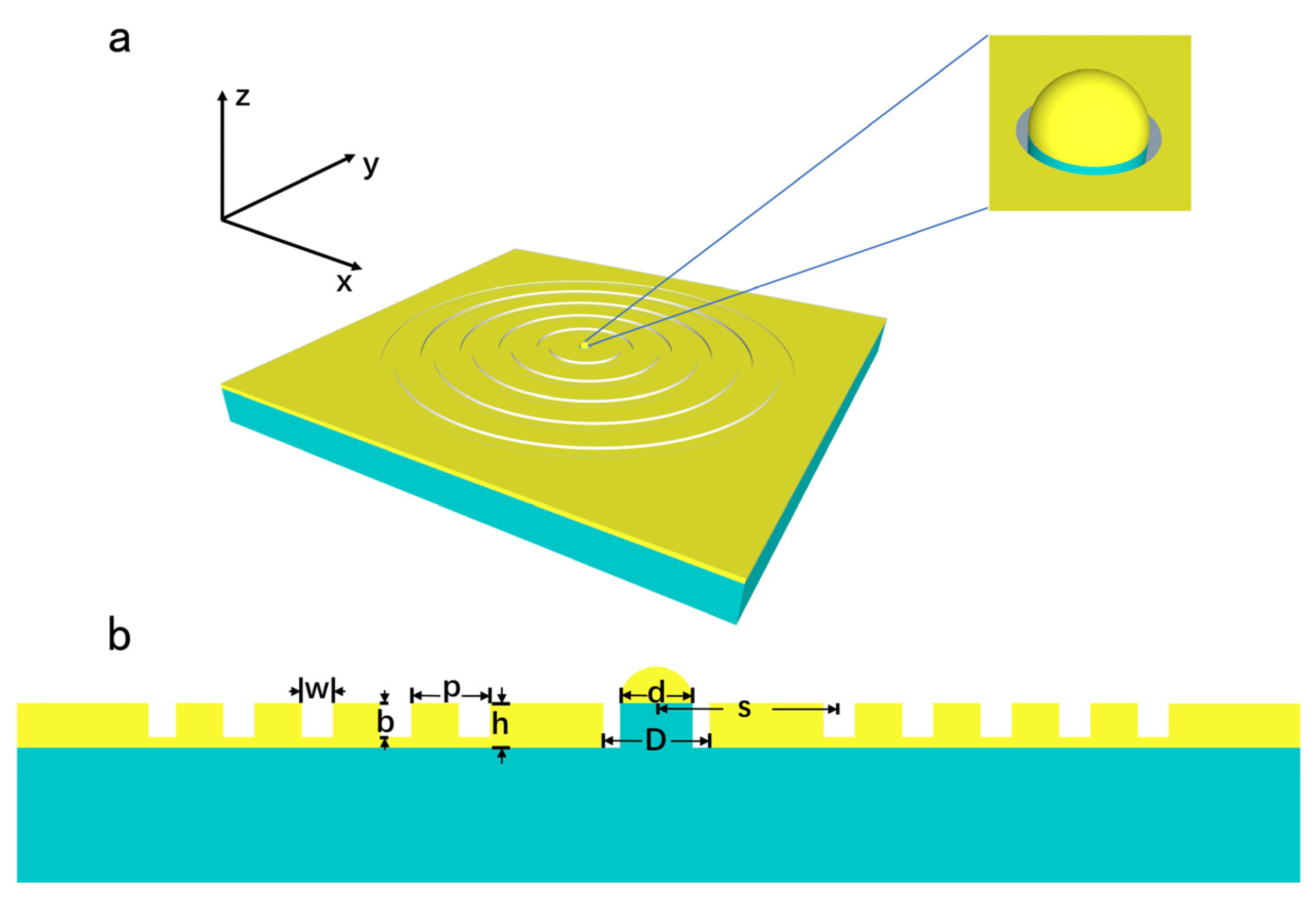
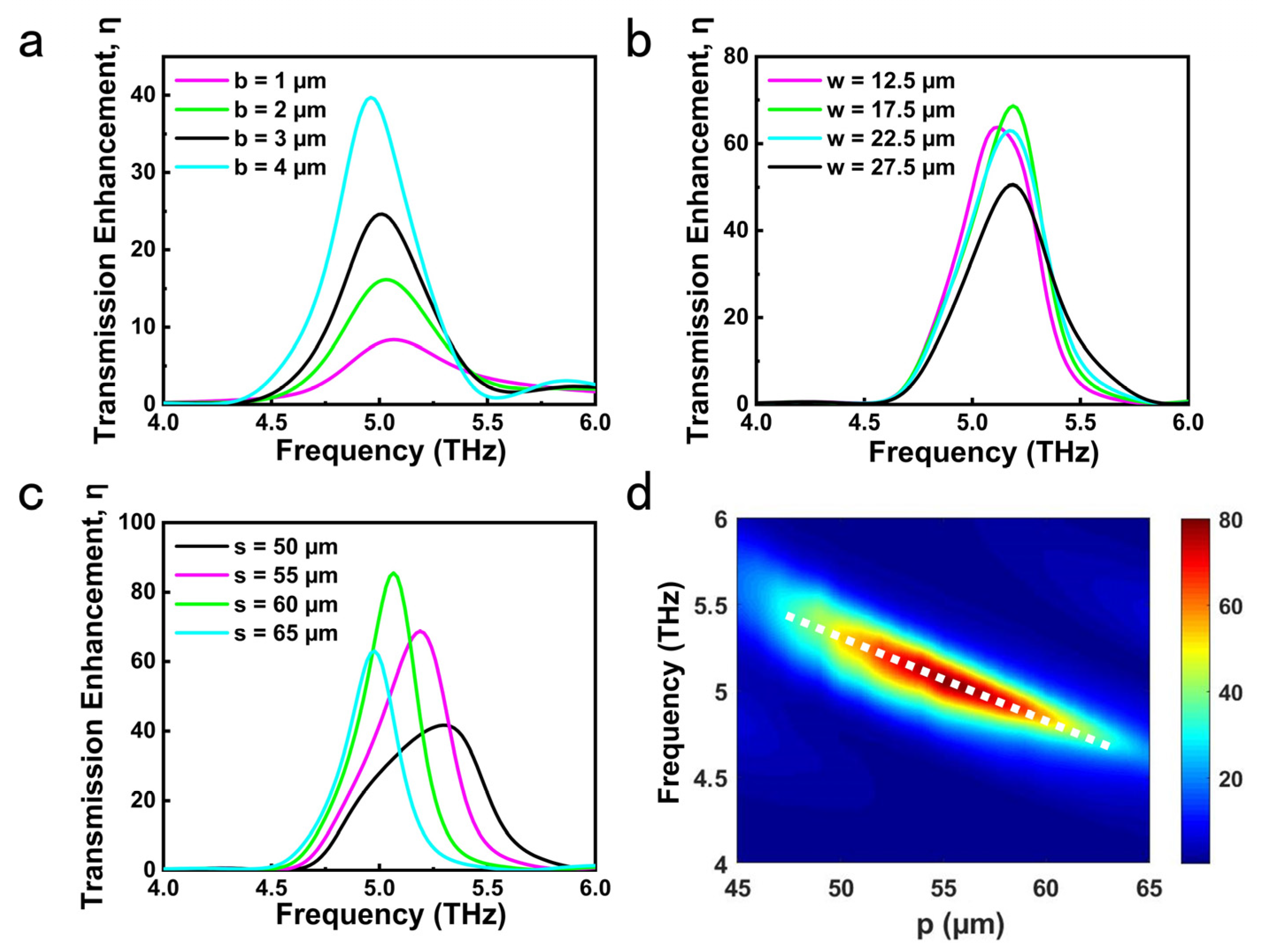
3.1. Groove Geometric Parameters

Figure 2 shows the variation of the transmission enhancement as a function of the structural parameters of grooves. The simulation of 5-groove HIHB structure is employed for parameter optimization to faster calculation. The corresponding transmission enhancement spectra of the HIHB structure at four different depth are summarized in Figure 2a. When b/w is smaller than the optimal shape ratio (i.e., b/w = 0.4), the deeper the grooves the higher the value of η, which is in agreement with O. Mahboub’s work [16]. This is due to that the SPPs mode can be excited when the groove depth is shallow [36], and increasing the groove depth can enhance the interaction between incident waves and gratings. Since the thickness of the gold film is fixed at 5 µm, b is set at 4 µm to enhance the normalized-to-area transmission as much as possible within the permissible range. Figure 2b shows the calculated transmission enhancement spectra of HIHB structures designed for different groove width ranging from 12.5 to 27.5 µm. The groove width has influence on the SPPs excitation and achieves the maximum η at w = 17.5 µm. The impact of the distance from the aperture center to the first groove is further investigated, and the results are summarized in Figure 2c. It can be verified that this distance has a strong influence on transmission intensity, because the interaction between SPPs and LSPRs is greatly affected by s [19]. The maximum transmission enhancement is observed at s = 60 µm. In order to further investigate the impact of the groove period p, Figure 2d depicts the color map of transmission enhancement spectra from p = 45 to 65 µm. The periodic grooves can couple incident light into surface plasmon waves, and propagate electromagnetic waves with wavelengths close to groove period. Therefore, the strong transmission peak redshifts with the increasing p, which is consistent to a prior report [37]. The optimal p matched with s = 60 µm for resonance peak at 5.07 THz is 55 µm. Based on the above exploration, the optimal groove parameters are b = 4 µm, w = 17.5 µm, s = 60 µm, p = 55 µm. Optimal geometric parameters obtained in this way are used as seeds for further exploration.

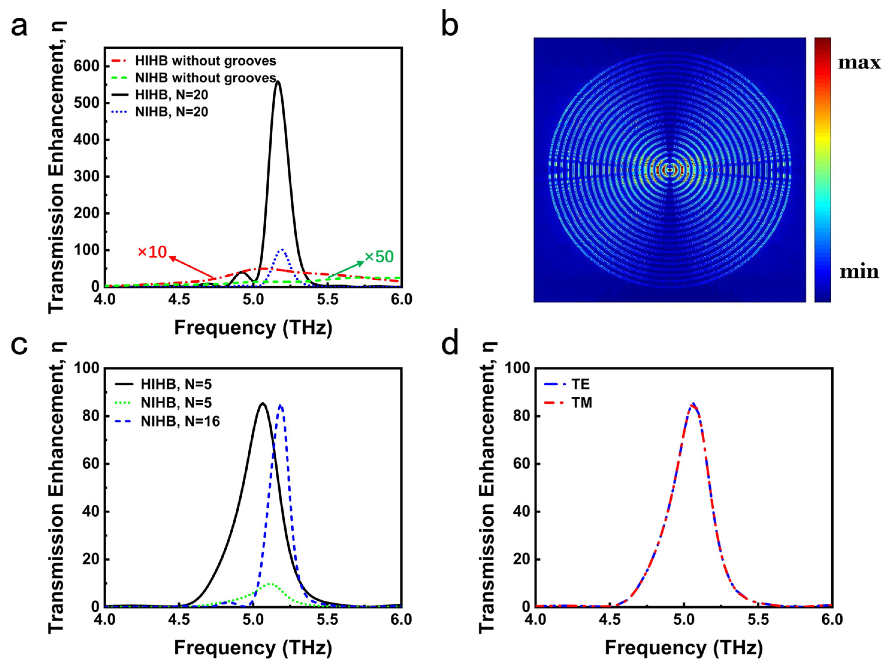
3.2. Enhanced THz Transmission and Its Polarization Independence

Figure 3a shows the transmission enhancement spectra comparison among the HIHB structure, the NIHB structure and the two structures without grooves. It is observed that the structure with concentric grooves has much greater transmission enhancement than that of only a single hole. The normalized-to-area transmission of grooved structure is much higher than 1, so the direct transmission of incident light plays a minor role. As shown in Figure 3b, it is the periodic grooves that can harvest a wide range of light and then squeeze the light into the central hole that results in a dramatic increase in normalized-to-area transmission. The transmission enhancement peak of the 20-groove HIHB structure is 556, and the maximum transmission enhancement of HIHB structure is more than 5.5 times that of NIHB structure. In addition, the hole diameter of the conventional bull’s eye structure is usually half of the resonance wavelength [38], which limits its response speed when used as a photodetector [39]. The HIHB structure can reduce the diameter of central hole down to 18 µm for an operating wavelength of 58 µm, as shown in Figure 3a. As shown in Figure 3c, the HIHB structure with 5 grooves is sufficient to achieve the same transmission enhancement as the NIHB structure with 16 grooves. Therefore, the entire grating size can be reduced greatly while maintaining the same light transmission performance as the conventional bull’s eye structure. The reason why the blue curve blueshifts relative to the black curve will be discussed in Section 3.3.2. Moreover, the transmission enhancement of HIHB structure is significantly higher than that of NIHB structure at N = 5. As shown in Figure 3d, transmission enhancement spectra of transverse electric (TE) and transverse magnetic (TM) polarized waves are numerically obtained. The transmission enhancement curves in both polarization directions almost coincide, implying that the HIHB structure is polarization-insensitive.

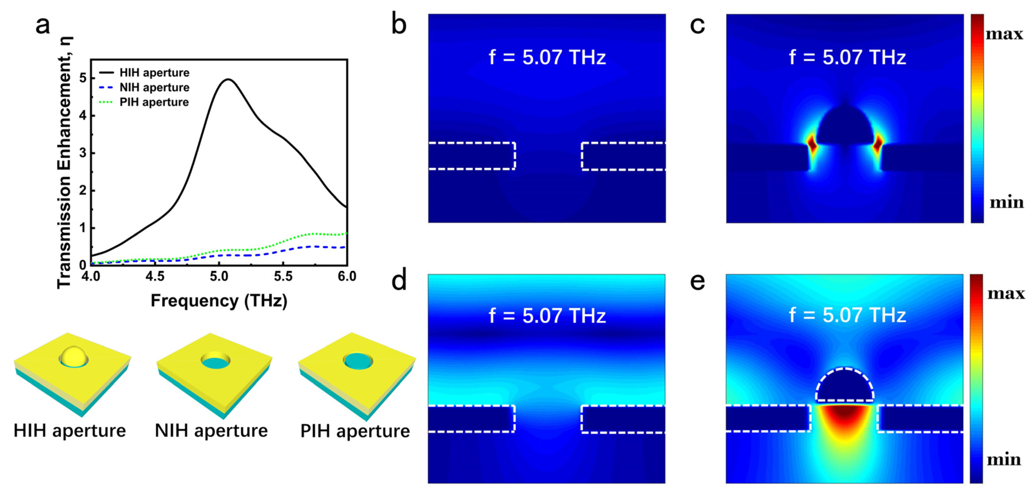
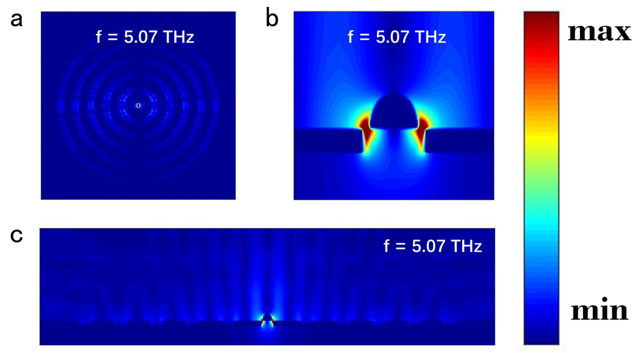
3.3. The Plasmon Resonances

As previously reported [40,41,42], periodic metallic grating has the ability of launching and focusing SPPs into its center. Metal particles are known to exhibit characteristic LSPRs mode [43,44]. By placing a hemispheric particle at the central aperture, it is possible to enhance the transmission of bull’s eye structure further. In this section, the generation of LSPRs mode and its coupling with SPPs mode are discussed.

3.3.1. Localized Surface Plasmon Resonances

Figure 4 presents the transmission enhancement spectra for three types of single aperture without grooves and the distributions of electric and magnetic fields near the hole at 5.07 THz. The schematic representations of HIH aperture, NIH aperture, and PIH aperture are illustrated in Figure 4a. The transmission enhancement spectra in Figure 4a shows the corresponding normalized-to-area transmission results for three different samples with equivalent aperture diameter (D = 18 µm). The difference in transmission enhancement between green and blue curves is much gentler, compared with that of the black curve. A little difference between them is due to the dielectric environment changing resulted from the introduction of supporting column in pillar-in-hole (PIH) aperture. As shown in Figure 4a, a resonance peak cannot be excited by the NIH aperture within the studied frequency region and only 0.28 normalized transmission is achieved at 5.07 THz. It can be seen from the electric field distribution in Figure 4b that resonance intensity located around the hole is weak. Meanwhile, the magnetic field is mainly distributed on the upper surface of gold film, as shown in Figure 4d. Only a little electromagnetic energy can penetrate the single aperture, as a result, the transmission enhancement is small. Figure 4a shows that the enhanced transmission for HIH aperture is 4.97 at a resonance frequency of 5.07 THz. The electric field distribution in Figure 4c shows that strong resonance is generated in the gap between the aperture and the hemisphere. This demonstrates the formation of LSPRs mode, which leads to the enhancement of transmission. As can be observed in Figure 4e, the strong magnetic field is confined at the bottom of the hemisphere, illustrating that the energy is strongly coupled into the hole. The hemisphere particle can excite LSPRs mode and thus significantly improve the normalized-to-area transmission of HIHB structure.

3.3.2. Coupling of SPPs and LSPRs

The surface plasmon polariton wavelength on a gold film surface is λ s p p = λ ε A u + ε A i r ε A u ε A i r [45], where λ is the wavelength of incident light. The parameters ε A u and ε A i r represent the relative permittivity of gold and air, respectively. According to Bragg coupling condition [46], the resonant wavelength of SPPs λ s p p is theoretically equal to the groove period p. In fact, p is slightly smaller than λ s p p due to the interaction between the field and the grooves that enlarges the optical path of the SPPs [19]. λ s p p tends to approach p as more grooves are added to the bull’s eye structure [19]. This is why the transmission enhancement peak of 16-groove NIHB structure blueshifts relative to that of 5-groove HIHB structure in Figure 3c. When the resonances of both SPPs and LSPRs occur at the same frequency, the strong interaction between these two modes gives rise to the enhancement of transmission [47]. According to Section 3.3.1., the frequency of LSPRs mode excited by the hemispheric particle is 5.07 THz. Therefore, the period of grooves is set to 55 µm to excite the SPPs mode at the same resonant frequency as the LSPRs mode. Figure 5 shows the relative electric field intensity distributions of the optimal HIHB structure with five grooves at f = 5.07 THz. It is observed in Figure 5a,c that the HIHB structure has a significant light concentration performance resulting from periodic grooves, which is the same with conventional bull’s eye structure. As shown in Figure 5b, there exists a strong electric field distribution in the gap between aperture and hemisphere. It displays the coupling of the SPPs mode and the LSPRs mode, which further enhances the light transmission. The interaction between hemisphere and grooves can be controlled by the distance from the central aperture to its nearest groove. At non-resonant frequencies, the electric field intensity of HIHB structure and HIH aperture is weak, indicating that SPPs mode and LSPRs mode are weak. Therefore, the HIHB structure at non-resonant frequencies has a poor ability to converge light or assist light transmission.

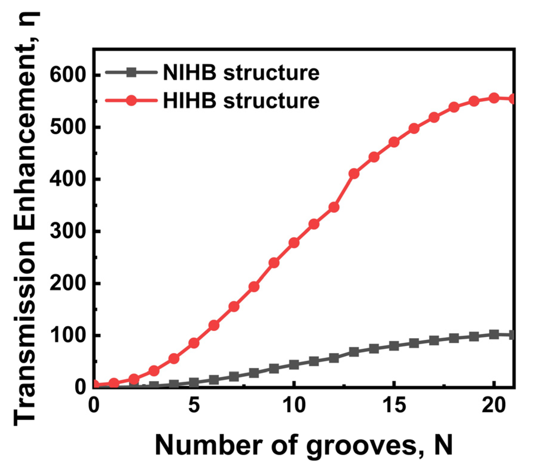
3.4. Comparison of HIHB and NIHB Structure with Varying N

The number of grooves is increased from 0 to 21 on the basis of the optimized groove geometric parameters described above. Figure 6 shows the transmission enhancement peak as a function of the number of grooves N. When N > 7, the transmission enhancement peak of HIHB structure is around six times that of NIHB structure. In the range of N ≤ 7, which is more promising for applications, the transmission enhancement peak of HIHB structure exceeds that of NIHB structure by a factor of 7. As N increases, the transmission enhancement peak gradually increases because an extending range of incident light can be collected with increasing number of grooves. The transmission enhancement of the HIHB structure reaches saturation at N = 20, which is similar as that of NIHB structure. If grooves are continued to be added, the captured light would be re-irradiated and the propagation loss of SPPs increases gradually [48]. As pointed out in the reference [49], varying the groove width and groove depth can increase the number of grooves involved in transmission enhancement. Therefore, it is justified to speculate that changing the geometric parameters of the outermost groove can change the corresponding N at saturation, which is applicable to both HIHB and NIHB structures.

4. Conclusions

In this study, we have presented a novel method of designing a bull’s eye structure by adding a concentric hemisphere at the central aperture. Based on the interference of SPPs and LSPRs mode, the normalized transmission is significantly improved for the subwavelength aperture at the THz band. We have optimized the geometric parameters of the groove and theoretically analyzed the influence of each geometric parameter on the plasmon resonance. The maximum normalized-to-area transmission achieved by the optimized structure is 556. The transmission enhancement peak of HIHB structure at N = 5 is the same as that of NIHB structure at N = 16, so the modified structure can significantly reduce the device size. Meanwhile, due to the overall symmetry of the HIHB structure, it is insensitive to the polarization direction of incident electromagnetic wave. Ultimately, the performance of the HIHB structure and NIHB structure is contrasted by increasing the number of grooves. The normalized transmission peaks of the HIHB structure exceeded five times that of the NIHB structure, regardless of the number of grooves. The theoretical analysis of the presented structure is instructive for future applications of the bull’s eye structure.

Author Contributions

Conceptualization, M.S. and Y.S.; methodology, M.S., Y.S. and J.S.; software, X.W. and F.Y.; validation, M.S. and Y.L.; formal analysis, M.S.; investigation M.S.; resources, Y.S.; data curation, M.S., Y.Z., M.L., S.S. and S.Z.; writing—original draft preparation, M.S.; writing—review and editing, M.S., Y.S. and J.S.; visualization, M.S.; supervision, M.S. and Y.S.; project administration, M.S.; funding acquisition, Y.S. All authors have read and agreed to the published version of the manuscript.

Funding

This work was supported by the National Natural Science Foundation of China under Grant 61805127, the Natural Science Foundation of Shandong Province under Grant ZR2019BF014, and China Postdoctoral Science Foundation funded project under Grant 2015M582073.

Institutional Review Board Statement

Not applicable.

Informed Consent Statement

Not applicable.

Data Availability Statement

Not applicable.

Conflicts of Interest

The authors declare no conflict of interest.

References

  1. Arabi, H.E.; Joe, H.E.; Nazari, T.; Min, B.K.; Oh, K. A high throughput supra-wavelength plasmonic bull’s eye photon sorter spatially and spectrally multiplexed on silica optical fiber facet. Opt. Express 2013, 21, 28083–28094. [Google Scholar] [CrossRef] [PubMed]
  2. Agrawal, A.; Cao, H.; Nahata, A. Time-domain analysis of enhanced transmission through a single subwavelength aperture. Opt. Express 2005, 13, 3535–3542. [Google Scholar] [CrossRef] [PubMed]
  3. Wang, J.W.; Cheng, Y.; Liu, X.J. Manipulation of extraordinary acoustic transmission by a tunable bull’s eye structure. Chin. Phys. B 2014, 23, 054301. [Google Scholar] [CrossRef]
  4. Ko, H.; Kim, H.C.; Cheng, M. Light focusing at metallic annular slit structure coated with dielectric layers. Appl. Opt. 2010, 49, 950–954. [Google Scholar] [CrossRef]
  5. Carretero-Palacios, S.; Mahboub, O.; Garcia-Vidal, F.J.; Martin-Moreno, L.; Rodrigo, S.G.; Gene, C.; Ebbesen, T.W. Mechanisms for extraordinary optical transmission through bull’s eye structures. Opt. Express 2011, 19, 10429–10442. [Google Scholar] [CrossRef]
  6. Garcia-Vidal, F.J.; Lezec, H.J.; Ebbesen, T.W.; Martin-Moreno, L. Multiple Paths to Enhance Optical Transmission through a Single Subwavelength Slit. Phys. Rev. Lett. 2003, 90, 213901. [Google Scholar] [CrossRef]
  7. Ishi, T.; Fujikata, J.; Makita, K.; Baba, T.; Ohashi, K. Si Nano-Photodiode with a Surface Plasmon Antenna. Jpn. J. Appl. Phys. 2005, 44, L364–L366. [Google Scholar] [CrossRef]
  8. Ren, F.F.; Ang, K.W.; Ye, J.; Yu, M.; Lo, G.Q.; Kwong, D.L. Split Bull’s Eye Shaped Aluminum Antenna for Plasmon-Enhanced Nanometer Scale Germanium Photodetector. Nano Lett. 2011, 11, 1289–1293. [Google Scholar] [CrossRef]
  9. Okamoto, D.; Fujikata, J.; Ohashi, K. InGaAs Nano-Photodiode Enhanced Using Polarization-Insensitive Surface-Plasmon Antennas. Jpn. J. Appl. Phys. 2011, 50, 120201. [Google Scholar] [CrossRef]
  10. Chen, W.; Abeysinghe, D.C.; Nelson, R.L.; Zhan, Q. Plasmonic Lens Made of Multiple Concentric Metallic Rings under Radially Polarized Illumination. Nano Lett. 2009, 9, 4320–4325. [Google Scholar] [CrossRef] [Green Version]
  11. Aouani, H.; Mahboub, O.; Devaux, E.; Rigneault, H.; Ebbesen, T.W.; Wenger, J. Plasmonic Antennas for Directional Sorting of Fluorescence Emission. Nano Lett. 2011, 11, 2400–2406. [Google Scholar] [CrossRef] [PubMed]
  12. Aouani, H.; Mahboub, O.; Bonod, N.; Devaux, E.; Popov, E.; Rigneault, H.; Ebbesen, T.W.; Wenger, J. Bright Unidirectional Fluorescence Emission of Molecules in a Nanoaperture with Plasmonic Corrugations. Nano Lett. 2011, 11, 637–644. [Google Scholar] [CrossRef]
  13. Pournoury, M.; Arabi, H.E.; Oh, K. Strong polarization dependence in the optical transmission through a bull’s eye with an elliptical sub-wavelength aperture. Opt. Express 2012, 20, 26798–26805. [Google Scholar] [CrossRef] [PubMed]
  14. Ishihara, K.; Hatakoshi, G.; Ikari, T.; Minamide, H.; Ito, H.; Ohashi, K. Terahertz Wave Enhanced Transmission through a Single Subwavelength Aperture with Periodic Surface Structures. Jpn. J. Appl. Phys. 2005, 44, L1005–L1007. [Google Scholar] [CrossRef]
  15. Degiron, A.; Ebbesen, T.W. Analysis of the transmission process through single apertures surrounded by periodic corrugations. Opt. Express 2004, 12, 3694–3700. [Google Scholar] [CrossRef]
  16. Mahboub, O.; Palacios, C.S.; Genet, C.; Garcia-Vidal, F.J.; Rodrigo, S.G.; Martin-Moreno, L.; Ebbesen, T.W. Optimization of bull’s eye structures for transmission enhancement. Opt. Express 2010, 18, 11292–11299. [Google Scholar] [CrossRef]
  17. Fukai, R.; Nakagawa, T.; Kiyama, H.; Oiwa, A. Design of bull’s eye structures on gate-defined lateral quantum dots. Jpn. J. Appl. Phys. 2017, 56, 04CK04. [Google Scholar] [CrossRef]
  18. Yamada, A.; Terakawa, M. Reverse design of a bull’s eye structure based on the plasmonic far-field pattern. Opt. Express 2013, 21, 21273–21284. [Google Scholar] [CrossRef]
  19. Villate-Guio, F.; Lopez-Tejeira, F.; Garcia-Vidal, F.J.; Martin-Moreno, L.; Leon-Perez, F. Optimal light harvesting structures at optical and infrared frequencies. Opt. Express 2012, 20, 25441–25453. [Google Scholar] [CrossRef]
  20. Pournoury, M.; Joe, H.E.; Park, J.H.; Nazari, T.; Sung, Y.M.; Min, B.K.; Im, S.; Kim, D.; Oh, K. Polarization-dependent transmission through a bull’s eye with an elliptical aperture. Opt. Commun. 2014, 316, 1–4. [Google Scholar] [CrossRef]
  21. Ishihara, K.; Ohashi, K.; Ikari, T.; Minamide, H.; Yokoyama, H.; Shikata, J.; Ito, H. Polarization-dependent transmission through a bull’s eye with an elliptical aperture Terahertz-wave near-field imaging with subwavelength resolution using surfacewave-assisted bow-tie aperture. Appl. Phys. Lett. 2006, 89, 201120. [Google Scholar] [CrossRef]
  22. Xu, W.Z.; Ren, F.F.; Jevtics, D.; Hurtado, A.; Li, L.; Gao, Q.; Ye, J.; Wang, F.; Guilhabert, B.; Fu, L.; et al. Vertically emitting indium phosphide nanowire lasers. Nano Lett. 2018, 18, 3414–3420. [Google Scholar] [CrossRef] [PubMed]
  23. Wang, D.; Yang, T.; Crozier, K.B. Optical antennas integrated with concentric ring gratings: Electric field enhancement and directional radiation. Opt. Express 2011, 19, 2148–2157. [Google Scholar] [CrossRef]
  24. Hang, N.T.N.; Yang, Y.; Nam, N.Q.T.; Nogami, M.; Phuc, L.H.; Tri, N.H.; Cuu, H.V.; Long, N.V. Controlled Synthesis of Au Nanoparticles by Modified Polyol Methods: Determination of Their Size, Shape, and Crystal Structure. Crystals 2021, 11, 1297. [Google Scholar] [CrossRef]
  25. Sun, J.; Ding, Z.; Yu, Y.; Xie, C. A Theoretical Investigation about Photoswitching of Azobenzene Adsorbed on Ag Nanoparticles. Crystals 2022, 12, 248. [Google Scholar] [CrossRef]
  26. Zhong, T.; Zhang, H. Spoof surface plasmon polaritons excited leaky-wave antenna with continuous scanning range from endfire to forward. Chin. Phys. B 2020, 29, 094101. [Google Scholar] [CrossRef]
  27. Hu, X.; Liang, X.; Tang, L.; Liu, W. Enhanced Light Extraction Efficiency and Modulation Bandwidth of Deep-Ultraviolet Light-Emitting Diodes with Al Nanospheres. Crystals 2022, 12, 289. [Google Scholar] [CrossRef]
  28. Nazari, T.; Khazaeinezhad, R.; Kassani, S.H.; Jung, W.; Shin, I.; Kang, D.; Oh, K. Polarization dependent enhanced optical transmission through a sub-wavelength polygonal aperture surrounded by polygonal grooves. Opt. Express 2014, 22, 27476–27488. [Google Scholar] [CrossRef]
  29. Nazari, T.; Khazaeinezhad, R.; Jung, W.; Joo, B.; Kong, B.J.; Oh, K. Enhanced optical transmission through a star-shaped bull’s eye at dual resonant-bands in UV and the visible spectral range. Opt. Express 2015, 23, 18589–18601. [Google Scholar] [CrossRef]
  30. Yang, M.; Ren, F.F.; Pu, L.; Xiao, L.; Sheng, Y.; Wang, J.; Zheng, Y.; Shi, Y. Split Bull’s Eye Antenna for High-Speed Photodetector in the Range of Visible to Mid-Infrared. IEEE Photonics Technol. Lett. 2016, 28, 1177–1180. [Google Scholar] [CrossRef]
  31. Ghosh, R.R.; Dhawan, A. Extremely large near-field enhancements in the vicinity of plasmonic nanoantennas on top of bull’s eye structures exhibiting the extraordinary transmission of light. OSA Continuum 2021, 4, 193–211. [Google Scholar] [CrossRef]
  32. Kampouridou, D.; Feresidis, A. Broadband THz Corrugated Bull’s Eye Antennas. IEEE Access 2021, 9, 104460–104468. [Google Scholar] [CrossRef]
  33. Song, J.; Shi, Y.; Liu, X.; Li, M.; Wang, X.; Yang, F. Enhanced broadband extraordinary terahertz transmission through plasmon coupling between metal hemisphere and hole arrays. Opt. Mater. Express 2021, 11, 2700–2710. [Google Scholar] [CrossRef]
  34. Zhang, Q.; Hu, P.; Liu, C. Realization of enhanced light directional beaming via a Bull’s eye structure composited with circular disk and conical tip. Opt. Commun. 2015, 339, 216–221. [Google Scholar] [CrossRef]
  35. Ordal, M.A.; Bell, R.J.; Alexander, R.W.; Newquist, L.A.; Querry, M.R. Optical properties of Al, Fe, Ti, Ta, W, and Mo at submillimeter wavelengths. Appl. Opt. 1988, 26, 1203–1208. [Google Scholar] [CrossRef] [PubMed]
  36. Cui, Y.; He, Y.; Jin, Y.; Ding, F.; Yang, L.; Ye, Y.; Zhong, S.; Lin, Y.; He, S. Plasmonic and metamaterial structures as electromagnetic absorbers. Laser Photonics Rev. 2014, 8, 495–520. [Google Scholar] [CrossRef]
  37. Laux, E.; Genet, C.; Skauli, T.; Ebbesen, T.W. Plasmonic photon sorters for spectral and polarimetric imaging. Nat. Photonics 2008, 2, 161–164. [Google Scholar] [CrossRef]
  38. Lezec, H.J.; Degiron, A.; Devaux, E.; Linke, R.A.; Martin-Moreno, L.; Garcia-Vidal, F.J.; Ebbesen, T.W. Beaming Light from a Subwavelength Aperture. Science 2002, 297, 820–822. [Google Scholar] [CrossRef]
  39. Bhat, R.D.R.; Panoiu, N.C.; Brueck, S.R.J.; Osgood, R.M. Enhancing the signal-to-noise ratio of an infrared photodetector with a circular metal grating. Opt. Express 2008, 16, 4588–4596. [Google Scholar] [CrossRef]
  40. Xia, M.; Zhang, P.; Qiao, K.; Bai, Y.; Xie, Y.H. Coupling SPP with LSPR for Enhanced Field Confinement: A Simulation Study. J. Phys. Chem. C 2016, 120, 527–533. [Google Scholar] [CrossRef] [Green Version]
  41. Liu, Z.; Steele, J.M.; Lee, H.; Zhang, X. Tuning the focus of a plasmonic lens by the incident angle. Appl. Phys. Lett. 2006, 88, 171108. [Google Scholar] [CrossRef]
  42. Liu, Z.; Steele, J.M.; Srituravanich, W.; Pikus, Y.; Sun, C.; Zhang, X. Focusing Surface Plasmons with a Plasmonic Lens. Nano Lett. 2005, 5, 1726–1729. [Google Scholar] [CrossRef]
  43. Li, J.; Chen, S.; Yu, P.; Cheng, H.; Zhou, W.; Tian, J. Large enhancement and uniform distribution of optical near field through combining periodic bowtie nanoantenna with rectangular nanoaperture array. Opt. Lett. 2011, 36, 4014–4016. [Google Scholar] [CrossRef] [PubMed]
  44. Chen, Y.; Liu, X.; Chen, W.; Xie, Z.; Huang, Y.; Li, L. Effects of thickness & shape on localized surface plasmon resonance of sexfoil nanoparticles. Chin. Phys. B 2017, 26, 017807. [Google Scholar]
  45. Barnes, W.L.; Dereux, A.; Ebbesen, T.W. Surface plasmon subwavelength optics. Nature 2003, 424, 824–830. [Google Scholar] [CrossRef]
  46. Ren, F.F.; Xu, W.Z.; Ye, J.; Ang, K.W.; Lu, H.; Zhang, R.; Yu, M.; Lo, G.Q.; Tan, H.H.; Jagadish, C. Second-order surface-plasmon assisted responsivity enhancement in germanium nanophotodetectors with bull’s eye antennas. Opt. Express 2014, 22, 15949–15956. [Google Scholar] [CrossRef]
  47. Brunazzo, D.; Descrovi, E.; Martin, Q.J.F. Narrowband optical interactions in a plasmonic nanoparticle chain coupled to a metallic film. Opt. Lett. 2009, 34, 1405–1407. [Google Scholar] [CrossRef] [PubMed]
  48. Yu, Z.; Veronis, G.; Fan, S.; Brongersma, M.L. Design of midinfrared photodetectors enhanced by surface plasmons on grating structures. Appl. Phys. Lett. 2006, 89, 151116. [Google Scholar] [CrossRef]
  49. Janssen, O.T.A.; Urbach, H.P.; ’t Hooft, G.W. Giant Optical Transmission of a Subwavelength Slit Optimized Using the Magnetic Field Phase. Phys. Rev. Lett. 2007, 99, 043902. [Google Scholar] [CrossRef] [Green Version]
Figure 1. Schematic representation of the HIHB structure under study. (a) A three-dimensional schematic of the HIHB structure with an enlarged view of 3D hemispherical structure shown above; (b) cross profile shows the relevant parameters of the designed structure; b, w, s and p are the groove depth, the groove width, the distance from the aperture center to the first groove and the groove period, respectively. The hole diameter D = 18 µm, the film thickness h = 5 µm, and the hemisphere diameter is 15 µm.
Crystals 12 01210 g001
Figure 2. Variation of the transmission enhancement spectra as a function of structural parameters of grooves. (a) Effect of the groove depth on the transmission enhancement of the HIHB structure (w = 30 µm, s = 55 µm, p = 60 µm, N = 5); (b) effect of the groove width on the transmission enhancement of the modified structure (b = 4 µm, s = 55 µm, p = 60 µm, N = 5); (c) effect of the distance from the aperture to the first groove on the transmission enhancement of the modified structure (b = 4 µm, w = 17.5 µm, p = 60 µm, N = 5); (d) the color map of transmission enhancement spectra for the HIHB structure (b = 4 µm, w = 17.5 µm, s = 60 µm, N = 5) with different groove period p.
Crystals 12 01210 g002
Figure 3. (a) The transmission enhancement spectra for 4 cases of structure; (b) top view of the electric field distribution of the HIHB structure at N = 20; (c) a comparison of the transmission enhancement spectra for these two structures; (d) polarization independence of transmission enhancement for TE and TM.
Crystals 12 01210 g003
Figure 4. (a) The transmission enhancement spectra and schematic representations for three cases of aperture without grooves; the electric field distributions for (b) NIN aperture and (c) HIH aperture; the magnetic field distributions for (d) NIN aperture and (e) HIH aperture.
Crystals 12 01210 g004
Figure 5. Electric field distributions of the HIHB structure at 5.07 THz. (a) Top view of the electric field distribution observed at the film’s surface; (b) electric field intensity distribution near the aperture; (c) electric field intensity distribution in the cross section of the proposed structure.
Crystals 12 01210 g005
Figure 6. Normalized transmission versus number of grooves based on the optimized geometrical parameters.
Crystals 12 01210 g006
Publisher’s Note: MDPI stays neutral with regard to jurisdictional claims in published maps and institutional affiliations.

