Article

Piezoelectric Elements with PVDF–TrFE/MWCNT-Aligned Composite Nanowires for Energy Harvesting Applications

1
Department of Microelectronics, Technical University of Sofia, 1000 Sofia, Bulgaria
2
Department of Electrical Engineering, Lakehead University, Thunder Bay, ON P7B5E1, Canada
3
Department of Mechanics, Technical University of Sofia, 1000 Sofia, Bulgaria
*
Author to whom correspondence should be addressed.
Crystals 2023, 13(12), 1626; https://doi.org/10.3390/cryst13121626
Submission received: 3 November 2023 / Revised: 17 November 2023 / Accepted: 22 November 2023 / Published: 23 November 2023
(This article belongs to the Special Issue Photoelectric Functional Crystals)

Abstract

:
A self-sustainable power supply function with flexibility, mechanical stability, and lightweight quality is among the required properties for pressure sensors and other low-power-consuming electronics and wearable devices. In this work, a poly(vinylidene fluoride-trifluoroethylene)/multi-walled carbon nanotube (P(VDF–TrFE)/MWCNT) composite was prepared to increase the electrical conductivity of the piezoelectric polymer and, thus, improve its electrical power generation capabilities. It was soaked by injection molding through an anodic aluminum oxide membrane to align vertically with the dipoles and exclude the possibility of dipole moment quenching. The composite membrane-type element exhibited an excellent piezoelectric coefficient d33 of 42 pC/N at a frequency of 50 Hz and an applied force intensity of 10 N, while the sensitivity was ~375 µV/g, which is favorable for self-powered pressure sensor application. The resulting composite element was utilized to generate the piezoelectric signal and to investigate the dependence of the electromechanical behavior on the surface roughness, morphology, and contact interface resistance.

1. Introduction

Wearable alternative energy sources, such as piezoelectric generators activated by human motion or other sources of vibrations, have attracted great attention [1,2,3]. Flexibility is important to ensure the following variety of reliefs and curvatures, including human skin or organs, which is favorable for the acquisition of biological signals. Therefore, biocompatibility and utilizing eco-friendly materials and technologies is also a requirement [4,5,6]. The fabrication of portable generators is mainly based on thermoelectric [7,8], photoelectric [9,10], piezoelectric [11,12], and triboelectric effects [13,14].
Piezoelectric polymers can be easily deformed to generate an electric charge via different mechanical stimuli, such as bending or twisting, due to the direct piezoelectric effect. Because of their low cost, easy, and large-area deposition, good chemical stability, and biocompatibility, piezoelectric polymers are considered excellent candidates for the fabrication of piezoelectric transducers (harvesters or sensors). When they are subjected to a force (compression, tension, or cyclic bending), the dipoles orient in different directions to each other, weakening the piezoelectric response. Therefore, the single-direction alignment of the dipoles is beneficial for the energy-harvesting properties. The conversion efficiency of elements based on piezoelectric polymers is lower compared to those of the piezoelectric oxides including, in particular, lead–zirconium titanate. Thus, at a weak mechanical force, the piezoelectric output results in a weak electrical signal, which is additionally limited by the low current through the polymeric chains.
The polymer poly(vinylidene fluoride-trifluoroethylene) (PVDF–TrFE) is a widely investigated piezoelectric material with the best performance among the other organic materials exhibiting similar behavior. Its β-piezoelectric crystallization phase is responsible for the strong piezoelectric response [15]. If the dipoles in the β-phase are aligned in one and the same direction, the polymer generates the strongest piezoelectric signal [16]. In order to achieve such an effect, template-assisted growth can facilitate molecules to organize into a specific chain conformation, which is the β-phase, without using the strong poling electric field of MV per cm or the high-voltage electrospinning process [17,18]. Moreover, the walls of the template could prevent the disordering of the dipoles and quenching of the polarization fields. This polymer is highly rigid, making it unsuitable for stretchable or bendable devices. To overcome this limitation, mixtures of PVDF–TrFE with the addition of soft material collecting the stress have been broadly studied [19].
It has been found that composites between carbon nanotubes and the PVDF polymer or its co-polymers obtained a high β phase (~80%) if the weight percent ratio of the carbon was greater than 0.2 wt% [20]. In addition, the electrical conductivity along the fiber is expected to increase, which can gain the output electrical power density as a product of the voltage and current per unit area (and aspect ratio in the case of nanostructuring). Therefore, carbon materials play the role of fillers in PVDF-based composites to tailor the piezoelectric properties of polymers [21,22]. A dry press-coating process using a combination of multi-walled carbon nanotubes (MWNTs) and polyvinylidene fluoride (PVDF) as a dry powder composite alongside etched Al foil as a current collector was explored for the electrode function in a battery structure [23]. Due to the great mechanical stability and current collecting properties, it has been observed that the highest reversible discharge capacity of 149.7 mAhg−1 and capacity retention of 77.7% occur after 250 cycles. The piezoresistive response of the PVDF/CNT composite has also been investigated, and a higher saturation current has been observed compared to the bare PVDF, which improves the electromechanical coupling factor [24]. Nanofiber composites of perovskite halide CsPbBr3 nanocrystals and carbon nanotubes (CNTs) with an optimal content of 0.3 wt% CNTs dispersed in a (P(VDF–TrFE)) have been found to exhibit a current of ~1128 nA at a strain of 1.19% with a bending frequency of 2.5 Hz, which is more than 10 times higher compared to the P(VDF–TrFE) nanofiber harvester. It has been suggested that space-charge polarization is responsible for the high electromechanical coupling due to the CNT content [25]. Multi-walled carbon nanotubes and (MWCNT)-BaTiO3/PVDF piezoelectric composite films have been prepared using electrospinning for energy harvesting and sensing. The generated energy was produced due to a current of approximately 760 nA, and the piezoelectric signal remained stable even after 1800 cycles [26]. The PVDF/ZnO/CNTs nano-reinforced composite was deposited via solution casting, and its piezoelectric properties were investigated by applying uniaxial cyclic tensile deformation. The resulting element exhibited a current of 610 nA [27]. PVDF–BaTiO3-MWCNT has been deposited by solution cast at an optimum content of 0.5 wt% CNT, and the maximum possible force that the element could take was 2N, and the current was 660 nA [28].
The proposed solutions are complex and contain additional inorganic piezoelectric material, which gives an added value to the piezoelectric charge, contributing to the polarization and harvesting ability of the polymeric material. The simpler case of one filler in the composite has been proposed by Levi et al. [29], who found that P(VDF–TrFE)/single-walled carbon nanotubes (SWCNTs) prepared by solution casting exhibited a higher piezoelectric coefficient of 25 pC/N than the pure P(VDF–TrFE) film, with 20 pC/N. PVDF/MWCNT 3D foam has been fabricated, and it is concluded that the electrostatic interaction between the carbon nanotubes provokes the reorganization of the dipoles in the polymer to be more stretched, thus contributing to the enhancement of the β phase at 2 wt% of MWCNT [30]. In these cases, however, the thickness of the composite material is beyond 1 mm, which hinders miniaturization.
In this study, the planar energy harvesting element with P(VDF–TrFE)/MWCNT composites was fabricated by injection molding in a template of anodic aluminum oxide to form nanowires. After the deposition of the metal thin electrode on the top, the membrane element was subjected to cyclic bending, and its generation ability and long-term stability were explored. The degree of filling for the AAO nanotubes was monitored, as well as the surface roughness, which is important for the electrode interface. The piezoelectric coefficient indicates an enhanced piezoelectric response, making the element a potential candidate for nano-generator fabrication. The contact resistance and interface capacitance are negligible, which is related to the low surface roughness. This is favorable for the current flow and facilitates the production of electrical energy.
The described fabrication method and characterization of P(VDF–TrFE)/MWCNT composites demonstrate several aspects of novelty, originality, and importance. The injection molding of P(VDF–TrFE)/MWCNT composites into a template of AAO to form nanowires is a unique manufacturing approach. This method combines the advantages of both piezoelectric polymer composites and AAO template synthesis, allowing for the controlled nanoscale structuring of the composite material. The investigation of the generation ability and long-term stability of the P(VDF–TrFE)/MWCNT composite under cyclic bending conditions represents an original aspect of the research. Understanding the performance of the composite material under dynamic bending loads is crucial to determining its suitability for applications such as energy harvesting or nanogenerators. The observation of an enhanced piezoelectric response, as indicated by the piezoelectric coefficient, is significant in the field of piezoelectric materials. This finding suggests that the fabricated P(VDF–TrFE)/MWCNT composite has the potential to be used in nano-generator fabrication, which could have notable implications for energy harvesting in small-scale devices. The negligible contact resistance and interface capacitance, which is attributed to the low surface roughness, are important factors for efficient electrical energy production in the composite material. This aspect highlights the potential of the fabricated P(VDF–TrFE)/MWCNT composite to generate electrical energy with minimal losses.

2. Experimental Section

Polymer P(VDF–TrFE) ink was purchased from Nanopaint (Braga, Portugal); MWCNTs (>90% carbon basis, D × L 110–170 nm × 5–6 μm) were purchased from Merck (Darmstadt, Germany) and dissolved in N,N-dimethylformamide (DMF, Sigma Aldrich, Saint Louis, MO, USA). The previous results (unpublished) showed that more stable piezoelectric coefficients are obtained with 0.2 wt% MWCNTs among 0.5, 0.75, and 1 wt%. They are dispersed in the DMF solvent using an ultrasonic bath for the uniform dispersion of the nanotubes. This is the reason to focus on this ratio only. Then, P(VDF–TrFE) ink was mixed with the solution of the MWCNT solvent and polystyrene powder and stirred for homogeneity. The polymer ink was then injected into a syringe that soaked the anodic aluminum oxide (AAO). The oxide array consisted of two-sided open nanotubes with an average diameter of 500 nm and length of 6 μm. Vacuum suction was performed at the back side of the AAO membrane, penetrating the ink in-depth in the AAO nanotubes due to the capillary forces. The fabrication process of the AAO membrane is described elsewhere [31]. At the end, the top and bottom electrode thin films of silver (99.99%, Kurt J. Lesker, Dresden, Germany) were thermally evaporated in a vacuum coater CY Scientific Instrument (Zhengzhou, China) and then linked with copper tape for the electromechanical tests. Atomic force microscopy in the non-contact mode was conducted on AFM Nanosurf Easyscan 2 (Liestal, Switzerland). Surface morphology and cross-section views are monitored via scanning electron microscopy (SEM) combined with an Energy Dispersive X-ray (EDX) microanalysis (Lyra Tescan, Brno, Czech Republic) for the distribution of chemical elements along the length of the AAO nanotubes. The piezoelectric coefficient d33 was measured using a PolyK quasi-static piezoelectric meter with the static force sensor PK-D3-F10N (State College, PA, USA). Contact resistance and interface capacitance were measured using an impedance analyzer IM3590 Hioki (Hioki E.E., Nagano, Japan). To generate voltage from the samples and test them to multiple bending cycles, a free-standing cantilever method was used, realized by the lab-made tester, and reported elsewhere [32]. The current flow was measured using a picoammeter Keithley 6485 (Keithley Instruments, OH, USA). The shape and the periodicity of the output signal were observed with a digital oscilloscope Tektronix TDS1002B (Beaverton, OR, USA).

3. Results and Discussion

An image of the prepared P(VDF–TrFE)/MWCNT composite membrane attached to the vibrational tester with copper tape is shown in Figure 1a. The violet-blue color on the top comes from the thin silver electrode. The fabrication process is illustrated in Figure 1b.
The initial anodization of the aluminum for the AAO template was conducted at a voltage of 100 V, an electrolyte temperature of 13 °C, and deposition time of 10 min to achieve adhesion with the photoresist PR (positive, ma-P 1215, Microresist Technology, Germany), which is responsible for the localization of the anodization zone. This preventive protection of the anode contact area by applying a photoresist was necessary to avoid the undercutting of the oxide layer during growth. Afterward, the complete etching of the oxide layer was conducted with an aluminum etching solution to remove the initially formed oxide, which is not geometrically uniform. Final anodization (reanodization) was necessary to complete the AAO template with regular and uniformly distributed nanopores (nanotubes) in size and was conducted at a voltage of 150 V, an electrolyte temperature of 13 °C and deposition time of 120 min. An AAO membrane was formed by etching the aluminum substrate at the bottom sides and opening the bottoms of the oxide nanopores with an etcher of CrO3 + H3PO4 and a temperature of 20 °C. The filtering screen is located at the backside of the AAO to the extraction gate of the outlet nozzle. On the opposite side, on another movable part, the ink is injected through the inlet nozzle.
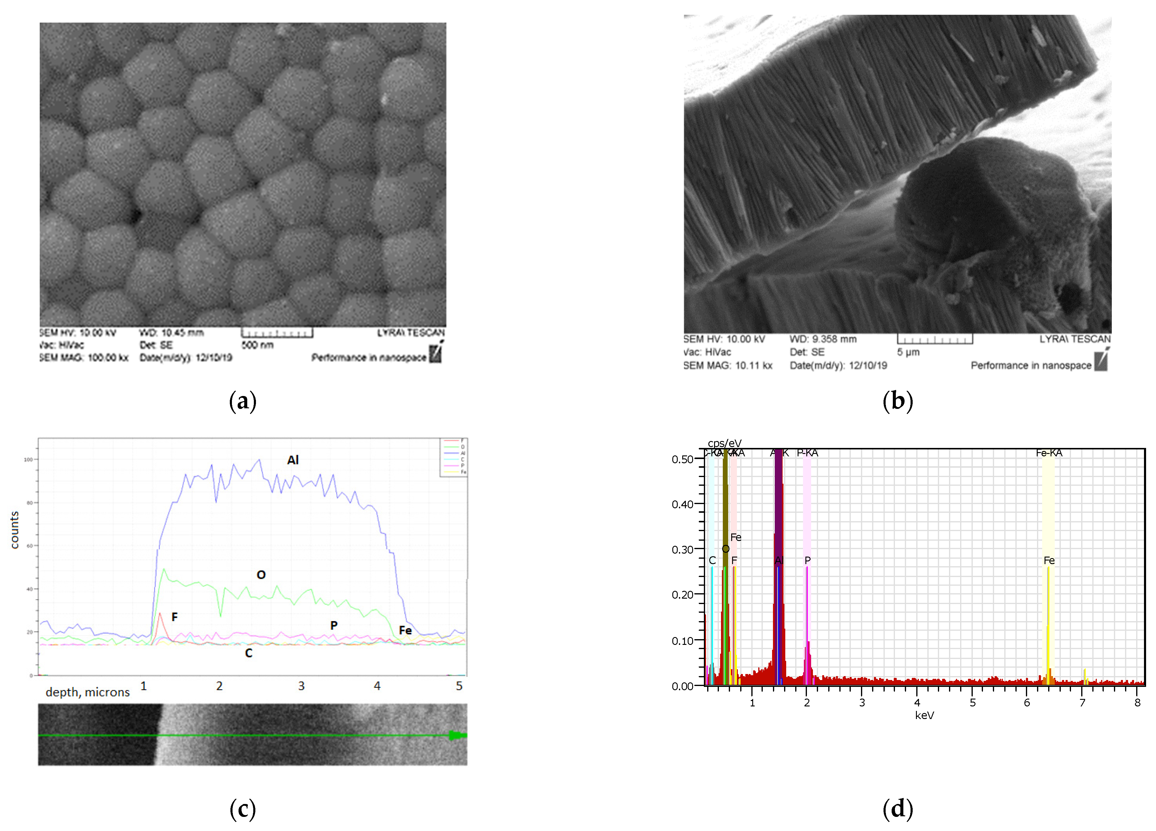
The nanowires were produced via the preliminary enlarging of the nanopores of AAO with a high voltage beyond 100 V, resulting in an increase in their average diameter from 200 nm to approximately 500 nm, as is visible in Figure 2a. It shows how the composite tightly fills the nanopore, forming nanograin top formations that need to be further studied for their effective roughness.
The larger nanopores facilitate the penetration of the mold and the formation of vertically aligned composite nanowires, which is visible from the cross-sectional SEM of the AAO template with nanowire fillers (Figure 2b). Some nanowires are broken due to the preparative cut of the sample. However, it is clearly visible that the non-damaged nanowires are characterized by highly aligned topography, starting from the top and ending at the bottom of the AAO matrix. The overall thickness of the sample is approximately 5.5 µm. It includes the PVDF–TrFE/MWCNT nanotubes with a length of approximately 5 µm as is visible from Figure 2b, together with the smoothing nanocoating from the conjugated polymer poly(3,4-ethylenedioxythiophene) polystyrene sulfonate (PEDOT:PSS) with a thickness of 80 nm, making the surface flatter and with 200 nm thin silver electrodes. To check the homogeneity of AAO filling with PVDF–TrFE/MWCNT, the nanotubes were scanned along the length using the EDX technique and chemical elements distribution, as shown in Figure 2c. It can be noted the presence of the main building elements (F, C) of the composite were present even outside of the AAO nanotubes. There are some traces of P and Fe that come from the etching solution to open the bottoms of the AAO nanotubes and the patterning of the electrode. The EDS spectrum of the filer of PVDF–TrFE/MWCNT in the AAO matrix is shown in Figure 2d. The results are in good agreement with the successfully reported piezoelectric oxide nanowire formation using template-assisted growth and non-chemical methods of synthesis [33].
For reliable electrical contact, the metalized surface should be planar and flat. Therefore, the effective roughness of the nanostructured coating is expected to be lower than 5% of the total thickness of the functional coatings [34]. The AFM 3D topography of the filled membrane, as presented in Figure 3a, shows the planarity and the distribution of the nanograins formed on the top of the filled AAO matrix. The mean roughness Sa was 59 nm, the root mean square (effective or RMS) grain-wise roughness was 77 nm, and the maximum height of the peak detected was 590 nm on a surface area of 625 µm and inclination angle due to the flexible base of the membrane of 0.15°. These values are more than four times lower than the values accepted as limiting for the quality of the metal/functional film interface and can be considered very favorable for the planned application as the energy losses due to contact parasitic effects can be minimized. Figure 3b is a 2D AFM image of the top of AAO nanotubes, filled by PVDF–TrFE/MWCNT, which shows the uniform distribution of the carbon nanotubes with white-colored tiny dots.
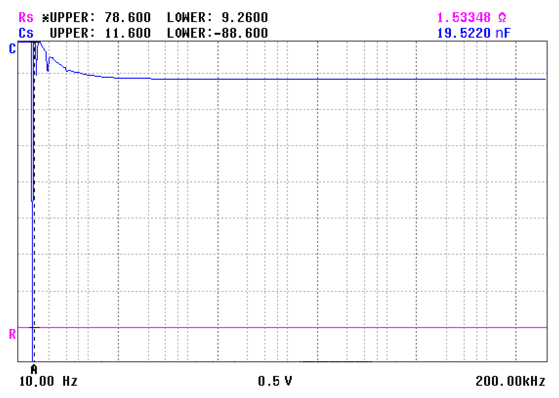
The contact effects were further investigated using impedance spectroscopy. The serial interface resistance and capacitance were extracted and presented at a bias voltage of 0.5 V, which is aligned with the expected range of the generated piezoelectric voltage (Figure 4). As can be seen, the overall range of change in both quantities was 9.2 ÷ 78.6 Ω for the serial resistance Rs and 11.6 ÷ (−88.6) nF for the interface capacitance Cs, respectively. These variations were caused by the dipoles collected near the interface and activated by the frequency of the bias voltage. The average values at low frequencies were reduced to approximately 1.5 Ω and 19.5 nF. These values are negligible and proved that the flat contact formed with the electrode, with a high contact area at the interface and the PVDF–TrFE/MWCNT surface, resulting from the low roughness of the surface.
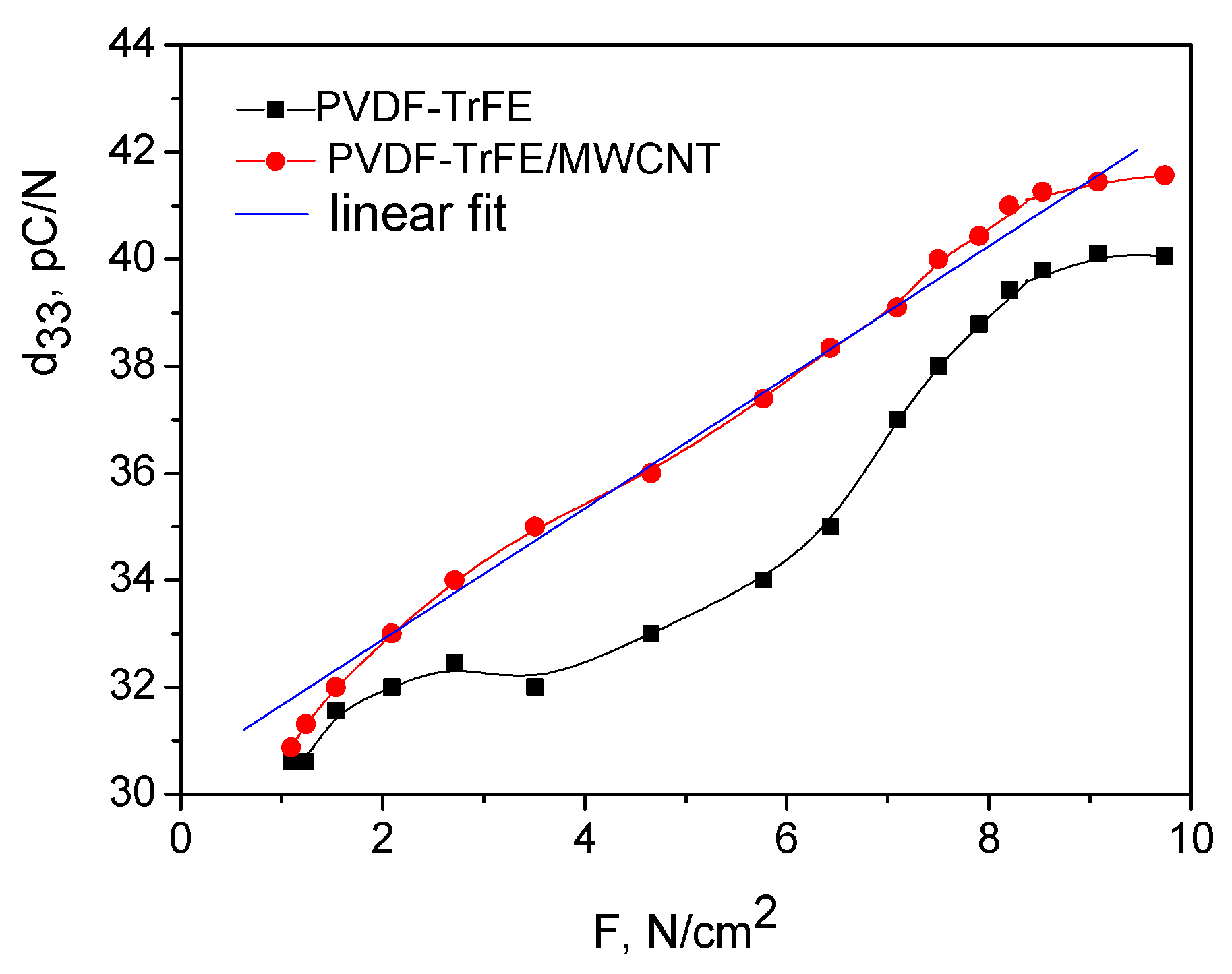
As a consequence, due to the presence of the MWCNT and the low values of the contact parameters, the PVDF–TrFE/MWCNT showed a higher piezoelectric coefficient than pure PVDF–TrFE, which has the advantage of eco-friendly energy harvesting elements (Figure 5). The difference between these two values in the range of the force applied from the setup is almost 9% and can be explained by several factors related to the presence of MWCNT in the PVDF–TrFE polymer. One of the possible reasons is the enhanced stress distribution over the composite material in the matrix. MWCNTs act as reinforcements, distributing the applied stress more evenly throughout the material [35]. This improved stress distribution results in a more linear piezoelectric response and reduces the non-linearities caused by localized stress concentrations in the pure PVDF–TrFE. Another possible reason could be the enhanced filler–matrix interactions. The strong interaction between the MWCNTs and the polymer in the matrix could facilitate better stress transfer, resulting in a more uniform strain distribution. In addition, the modified polymer chain orientation could be the third reason for the improved linearity. The MWCNTs can act as nucleation sites for the polymer chains, promoting a more aligned and polarized structure. This improved chain orientation can contribute to a more linear piezoelectric response [36]. Another benefit, probably due to the uniform vertical alignment of the produced nanowires, is the good linearity of the dependence of the d33 on the applied static force F, which is very favorable for lead-free sensor applications that can monitor human health by tracking processes like heartbeats, breathing, and blood pressure. The deviation from the liner fit (non-linearity) is 1.2%, which is negligible.
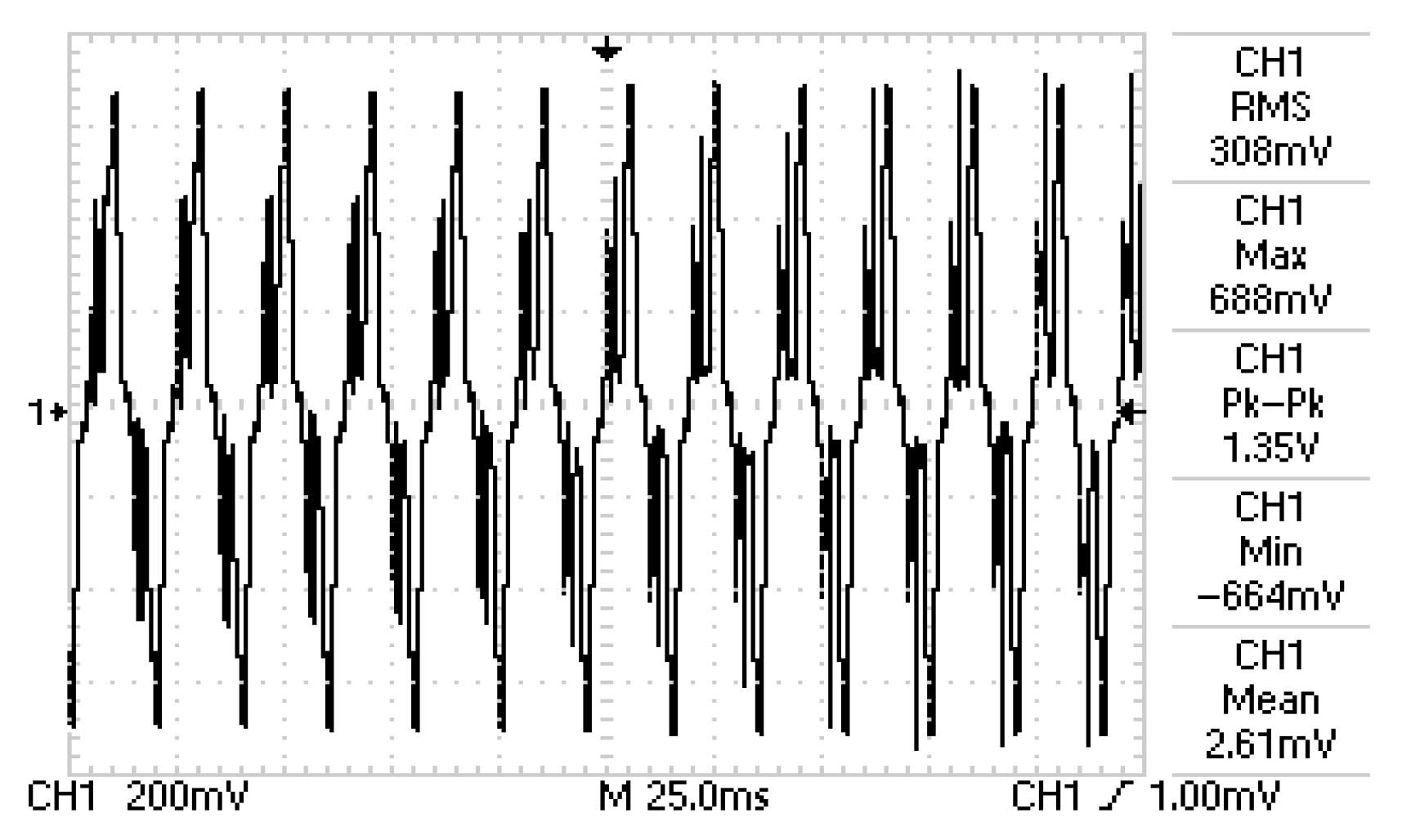
Figure 6 shows that the generated piezoelectric voltage is periodic and strong. The non-linear distortions of the voltage peaks were probably due to the grain-type nature of both sides of the filled membrane, where the copper tape formed contact with the silver thin electrodes. The maximum possible generated voltage was produced at the maximal possible mechanical stress of 90 g/cm2. Its peak value was 688 mV, which is more than twice higher than the generated voltage from PVDF-based elements with a spray-deposited piezoelectric polymer without MWCNT, as reported in our previous study [34]. The maximum generated voltage in [37] in the (dynamic) mode was 300 mV at a vibration load of 3.5 g/cm2 with the same frequency of 50 Hz. To determine the rate of the applied force to a piezoelectric element at a frequency of 50 Hz, the time period (T) of one complete cycle is calculated, and then the derivative with respect to time is taken. The time period (T) is the reciprocal of the frequency; so for a frequency of 50 Hz, the time period is 1/50 = 0.02 s (or 20 ms). The rate of change in the force with respect to time, also known as the force rate or loading rate, can be obtained by taking 1/T since each cycle occurs over a time period of T. So, for a frequency of 50 Hz, the rate of the applied force to the piezoelectric element is 1/T = 1/0.02 = 50 N/s. It is important to note that this calculation assumes a sinusoidal force waveform, which is valid for the studied case. The measured current was 1435 µA, which is, to the best of the authors’ knowledge, the highest reported value for a composite between CNT, MWCNT, and PVDF, or PVDF–TrFE. The highest current value found in the literature was 10 nA for 0.75 wt% of CNT, which was added to PVDF for the strain monitoring device [38]. The effect observed in our work can be ascribed both to the presence of MWCNT and nanostructuring, serving as the superposition and multiplying the effects in a single composite nanowire. The density of the peak electrical energy produced from this generator was 987 µW from an area of a square centimeter at a loading of 90 g/cm2 and a low-frequency activation.
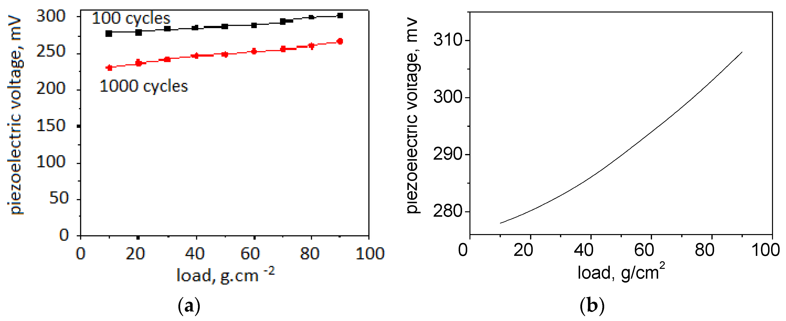
The AAO + PVDF–TrFE/MWCNT exhibited excellent flexibility and kept the generated piezoelectric voltage stable even after 1000 bends. The voltage decrease was averaged at 40 mV or 13% (Figure 7a) and withstood a tension/compression of 90 g/cm2 before beginning to tear. The high durability of the element was due to the superior mechanical characteristics of the anodic aluminum oxide, which is among the most stable materials in the form of a nanoporous membrane [39]. It has an additional function in this case and serves as a fixture for the nanowires during bending. Also, piezoelectric polymers are characterized by enhanced flexibility, and some authors report the enhancement of the mechanical strength of the membrane due to the incorporation of MWCNTs [40]. Figure 7b shows the rescaled dependence of the piezoelectric voltage generated at a certain applied load in the range of 10–90 g/cm2. The characteristic is nearly linear and shows that the generated voltage varies between 278 mV and 308 mV at these loadings. Therefore, it can be accepted that the sensitivity of the element is approximately 375 µV/g if the slight deviation from the linearity at the beginning of the curve is neglected. At low loads, there may be contact resistance between the electrode and the piezoelectric material, causing a non-linear behavior. This resistance may decrease as the load increases and the contact area expands, resulting in a more linear response. Due to the existing contact resistance, the PVDF–TrFE/MWCNT composite can exhibit an initial misalignment of the piezoelectric dipoles at lower loads. This misalignment can lead to a non-linear response, but as the load increases, the dipoles align more uniformly, leading to more linear behavior [38].
Further investigation is needed to establish the quantitative relationships between the nanotubes’ array geometry and the performance of the PVDF–TrFE/MWCNT composite. Based on a previous investigation of a vacuum-sputtered potassium niobate ceramic material that filled the nanopores of anodic aluminum oxide [33], it can be concluded that the aspect ratio of the nanoformations is of great importance for the optimization of the piezoelectric yield. It was demonstrated in [38] that the piezoelectric voltage increased with the length of the KNbO3 nanowires. This correlation suggests that the greater volume of the piezoelectric material in longer nanowires may contribute to the higher voltage output. Alternatively, a higher stress experienced by longer nanowires could also be a contributing factor. A higher nanopore diameter may allow for a greater degree of filling for the PVDF–TrFE/MWCNT composite. This increased filling degree can potentially lead to the higher volume fraction of the piezoelectric material, resulting in an improved piezoelectric response. With larger nanopores, there may be enhanced stress transfer between the AAO template and the PVDF–TrFE/MWCNT composite. This increased stress transfer, which could result in the more efficient transfer of the mechanical strain to the piezoelectric material, enhances the piezoelectric response of the composite structure but, at the same time, makes the structure more brittle. The same is expected to be valid for the longer nanowires. Therefore, the impact of the nanopore diameter and length on the performance of the composite PVDF–TrFE/MWCNT is a complex interplay of various factors, including the specific composite composition, growth conditions, and experimental setup. Therefore, further research and analysis are necessary to precisely determine the effect of the nanopores’ geometry on the performance of the composite material. Considering the great durability of the composite, it is expected that the mechanical strength could improve with the higher aspect ratio of the nanowires.

4. Conclusions

In this paper, we introduced a piezoelectric element based on a PVDF–TrFE/MWCNT composite nanowires created via injection molding through an anodic aluminum nanoporous membrane. The results assumed that the enhancement of the piezoelectric effect is the result of the combined effect of MWCNT and nanostructuring. The nanopatterning obtained with the AAO template-assisted growth enhances the interaction between the PVDF–TrFE matrix and MWCNTs due to the uniaxial alignment of the polymer chains along the length of the nanotubes.
The results indicate that the prepared piezoelectric converter can be used as an alternative energy source for low-power consumers and as a healthcare sensor due to its high efficiency, good linearity to vertical compressive forces, and robust mechanical flexibility. The prepared structures show no significant voltage degradation at long-term dynamic loading, revealing that the fabricated element possesses favorable mechanical stability, which is important for practical applications such as energy harvesting devices. Overall, the combination of the novel fabrication technique, the exploration of cyclic bending and long-term stability, an enhanced piezoelectric response, and favorable electrical properties make the described P(VDF–TrFE)/MWCNT composite research relevant, original, and potentially impactful in the field of piezoelectric materials and energy harvesting applications.
Future work will be focused on the following: a more detailed investigation of the geometry effect (aspect ratio of the nanowires) on the signal generation process (piezoelectric coefficient, current, and voltage) and an investigation of the effect of the AAO membrane’s shape and area on the stability of the produced piezoelectric voltage.

Author Contributions

Conceptualization—M.A., T.T. and K.N.; Formal analysis—M.A., B.K. and D.A.; Methodology: M.A.; Resources—M.A., D.A., I.K. and K.N.; Validation—M.A., D.A., B.K., T.T., K.N. and I.K.; Investigation—T.T., M.A., B.K. and K.N.; Visualization—M.A., T.T. and B.K.; Writing—original draft—M.A.; Writing—review and editing—all co-authors; Funding acquisition—I.K.; Project administration—I.K. All authors have read and agreed to the published version of the manuscript.

Funding

This research was funded by the European Regional Development Fund within the Operational Programme “Science and Education for Smart Growth 2014–2020” under the Project CoE “National center of mechatronics and clean technologies” BG05M2OP001-1.001-0008, 2018–2023. The APC was funded by the same project.

Data Availability Statement

The data is contained within the article.

Acknowledgments

The collaboration with the Lakehead University, Thunder Bay, Canada is under Erasmus+ project 2022-1-BG01-KA171-HED-000072406.

Conflicts of Interest

The authors declare no conflict of interest.

References

  1. Wang, L.; Fei, Z.; Wu, Z.; Ye, Y.; Qi, Y.; Wang, J.; Zhao, L.; Zhang, C.; Zhang, Y.; Qin, G.; et al. Wearable bending wireless sensing with autonomous wake-up by piezoelectric and triboelectric hybrid nanogenerator. Nano Energy 2023, 112, 108504. [Google Scholar] [CrossRef]
  2. Sun, Y.; Li, Y.-Z.; Yuan, M. Requirements, challenges, and novel ideas for wearables on power supply and energy harvesting. Nano Energy 2023, 115, 108715. [Google Scholar] [CrossRef]
  3. Hou, J.; Qian, S.; Hou, X.; Zhang, J.; Wu, H.; Guo, Y.; Xian, S.; Geng, W.; Mu, J.; He, J.; et al. A high-performance mini-generator with average power of 2 W for human motion energy harvesting and wearable electronics applications. Energy Convers. Manag. 2023, 277, 116612. [Google Scholar] [CrossRef]
  4. Divya, S.; Oh, T.H.; Bodaghi, M. 1D nanomaterial based piezoelectric nanogenerators for self-powered biocompatible energy harvesters. Eur. Polym. J. 2023, 197, 112363. [Google Scholar] [CrossRef]
  5. Rashmi, M.R.; Sairam, K.T.; Suresh, A. Energy harvesting through piezoelectric technology. Mater. Today Proc. 2023. [Google Scholar] [CrossRef]
  6. Xue, H.; Jiang, L.; Lu, G.; Wu, J. Multilevel Structure Engineered Lead-Free Piezoceramics Enabling Breakthrough in Energy Harvesting Performance for Bioelectronics. Adv. Funct. Mater. 2023, 33, 2212110. [Google Scholar] [CrossRef]
  7. Rodrigues-Marinho, T.; Correia, V.; Tubio, C.-R.; Ares-Pernas, A.; Abad, M.-J.; Lanceros-Méndez, S.; Costa, P. Flexible thermoelectric energy harvesting system based on polymer composites. Chem. Eng. J. 2023, 473, 145297. [Google Scholar] [CrossRef]
  8. Xie, Z.; Shi, K.; Song, L.; Hou, X. Experimental and Field Study of a Pavement Thermoelectric Energy Harvesting System Based on the Seebeck Effect. J. Electron. Mater. 2023, 52, 209–218. [Google Scholar] [CrossRef]
  9. Nan, Y.; Wang, X.; Xin, S.; Xu, H.; Niu, J.; Ren, M.; Yu, T.; Huang, Y.; Hou, B. Designed a hollow Ni2P/TiO2 S-scheme heterojunction for remarkably enhanced photoelectric effect for solar energy harvesting and conversion. J. Mater. Chem. C 2023, 11, 4576–4587. [Google Scholar] [CrossRef]
  10. Li, F.; Peng, W.; Wang, Y.; Xue, M.; He, Y. Pyro-Phototronic Effect for Advanced Photodetectors and Novel Light Energy Harvesting. Nanomaterials 2023, 13, 1336. [Google Scholar] [CrossRef]
  11. Feng, Z.; Zhao, Z.; Liu, Y.; Liu, Y.; Cao, X.; Yu, D.-G.; Wang, K. Piezoelectric Effect Polyvinylidene Fluoride (PVDF): From Energy Harvester to Smart Skin and Electronic Textiles. Adv. Mater. Technol. 2023, 8, 2300021. [Google Scholar] [CrossRef]
  12. Yan, D.; Wang, J.; Xiang, J.; Xing, Y.; Shao, L.-H. A flexoelectricity-enabled ultrahigh piezoelectric effect of a polymeric composite foam as a strain-gradient electric generator. Sci. Adv. 2023, 9, eadc8845. [Google Scholar] [CrossRef] [PubMed]
  13. Duan, Q.; Peng, W.; He, J.; Zhang, Z.; Wu, Z.; Zhang, Y.; Wang, S.; Nie, S. Rational Design of Advanced Triboelectric Materials for Energy Harvesting and Emerging Applications. Small Methods 2023, 7, 2201251. [Google Scholar] [CrossRef] [PubMed]
  14. Zhang, R.; Hummelgård, M.; Örtegren, J.; Andersson, H.; Olsen, M.; Chen, W.; Wang, P.; Dahlström, C.; Eivazi, A.; Norgren, M. Energy Harvesting Using Wastepaper-Based Triboelectric Nanogenerators. Adv. Eng. Mater. 2023, 25, 2300107. [Google Scholar] [CrossRef]
  15. Chakhchaoui, N.; Farhan, R.; Boutaldat, M.; Rouway, M.; Eddiai, A.; Meddad, M.; Hajjaji, A.; Cherkaoui, O.; Boughaleb, Y.; Van Langenhove, L. Piezoelectric β-polymorph formation of new textiles by surface modification with coating process based on interfacial interaction on the conformational variation of poly (vinylidene fluoride) (PVDF) chains. Eur. Phys. J. Appl. Phys. 2020, 91, 31301. [Google Scholar] [CrossRef]
  16. Guo, J.; Nie, M.; Wang, Q. Self-Poling Polyvinylidene Fluoride-Based Piezoelectric Energy Harvester Featuring Highly Oriented β-Phase Structured at Multiple Scales. ACS Sustain. Chem. Eng. 2021, 9, 499–509. [Google Scholar] [CrossRef]
  17. He, Z.; Rault, F.; Lewandowski, M.; Mohsenzadeh, E.; Salaün, F. Electrospun PVDF Nanofibers for Piezoelectric Applications: A Review of the Influence of Electrospinning Parameters on the β Phase and Crystallinity Enhancement. Polymers 2021, 13, 174. [Google Scholar] [CrossRef]
  18. Chandran, A.M.; Varun, S.; Mural, P.K.S. Development of self-poled PVDF/MWNT flexible nanocomposites with a boosted electroactive β-phase. New J. Chem. 2020, 44, 14578–14591. [Google Scholar] [CrossRef]
  19. Sekine, T.; Ito, K.; Shouji, Y.; Suga, R.; Yasuda, T.; Wang, Y.-F.; Takeda, Y.; Kumaki, D.; Dos Santos, F.D.; Tong, H.; et al. Robotic e-skin for high performance stretchable acceleration sensor via combinations of novel soft and functional polymers. Appl. Mater. Today 2023, 33, 101877. [Google Scholar] [CrossRef]
  20. Sun, L.L.; Li, B.; Zhang, Z.G.; Zhongb, W.H. Achieving Very High Fraction of β-Crystal PVDF and PVDF/CNF Composites and Their Effect on AC Conductivity and Microstructure through A Stretching Process. Eur. Polym. J. 2010, 46, 2112–2119. [Google Scholar] [CrossRef]
  21. Wu, A.Y.; Kong, J.; Zhang, C.; Liu, T.; Kotaki, M.; Lu, X. Polymorphism of Electrospun Polyvinylidene Difluoride/Carbon Nanotube (CNT) Nanocomposites: Synergistic Effects of CNT Surface Chemistry, Extensional Force and Supercritical Carbon Dioxide Treatment. Polymer 2012, 53, 5097–5102. [Google Scholar]
  22. Ahn, Y.; Lim, J.Y.; Hong, S.M.; Lee, J.; Ha, J.; Choi, H.J.; Seo, Y. Enhanced Piezoelectric Properties of Electrospun Poly(vinylidene fluoride)/Multiwalled Carbon Nanotube Composites Due to High β-Phase Formation in Poly(vinylidene fluoride). J. Phys. Chem. C 2013, 117, 11791–11799. [Google Scholar] [CrossRef]
  23. Ryu, M.; Hong, Y.-K.; Lee, S.-Y.; Park, J.H. Ultrahigh loading dry-process for solvent-free lithium-ion battery electrode fabrication. Nat. Commun. 2023, 14, 1316. [Google Scholar] [CrossRef]
  24. Mishra, S.; Kumaran, K.; Sivakumaran, R.; Pandian, S.P.; Kundu, S. Synthesis of PVDF/CNT and their functionalized composites for studying their electrical properties to analyze their applicability in actuation & sensing. Colloids Surf. A Physicochem. Eng. Asp. 2016, 509, 684–696. [Google Scholar]
  25. Han, J.; Kim, D.B.; Kim, J.H.; Kim, S.W.; Ahn, B.U.; Cho, Y.S. Origin of high piezoelectricity in carbon nanotube/halide nanocrystal/P(VDF-TrFE) composite nanofibers designed for bending-energy harvesters and pressure sensors. Nano Energy 2022, 99, 107421. [Google Scholar] [CrossRef]
  26. Lin, X.; Yu, F.; Zhang, X.; Li, W.; Zhao, Y.; Fei, X.; Li, Q.; Yang, C.; Huang, S. Wearable Piezoelectric Films Based on MWCNT-BaTiO3/PVDF Composites for Energy Harvesting, Sensing, and Localization. ACS Appl. Nano Mater. 2023, 6, 11955–11965. [Google Scholar] [CrossRef]
  27. Kumar, A.; Jaiswal, S.; Joshi, R.; Yadav, S.; Dubey, A.; Sharma, D.; Lahiri, D.; Lahiri, I. Energy harvesting by piezoelectric polyvinylidene fluoride/zinc oxide/carbon nanotubes composite under cyclic uniaxial tensile deformation. Polym. Compos. 2023, 44, 4746–4756. [Google Scholar] [CrossRef]
  28. Uddin, A.S.M.I.; Lee, D.; Cho, C.; Kim, B. Impact of Multi-Walled CNT Incorporation on Dielectric Properties of PVDF-BaTiO3 Nanocomposites and Their Energy Harvesting Possibilities. Coatings 2022, 12, 77. [Google Scholar] [CrossRef]
  29. Levi, N.; Czerw, R.; Xing, S.; Preethi Iyer, A.; Carroll, D.L. Properties of Polyvinylidene Difluoride−Carbon, Nanotube Blends. Nano Lett. 2004, 4, 1267–1271. [Google Scholar] [CrossRef]
  30. Xu, D.; Zhang, H.; Pu, L.; Li, L. Fabrication of Poly(vinylidene fluoride)/Multiwalled carbon nanotube nanocomposite foam via supercritical fluid carbon dioxide: Synergistic enhancement of piezoelectric and mechanical properties. Compos. Sci. Technol. 2020, 192, 108108. [Google Scholar] [CrossRef]
  31. Tsanev, T.; Aleksandrova, M.; Videkov, V. Study of nanoporous anodic aluminum oxide as a template filled with piezoelectric materials. In Proceedings of the 31st IEEE International Conference on Microelectronics, MIEL 2019, Nish, Serbia, 16–18 September 2019; pp. 125–128. [Google Scholar]
  32. Aleksandrova, M.P.; Tsanev, T.D.; Pandiev, I.M.; Dobrikov, G.H. Study of piezoelectric behaviour of sputtered KNbO3 nanocoatings for flexible energy harvesting. Energy 2020, 205, 118068. [Google Scholar] [CrossRef]
  33. Aleksandrova, M.; Tsanev, T.; Gupta, A.; Singh, A.K.; Dobrikov, G.; Videkov, V. Sensing Ability of Ferroelectric Oxide Nanowires Grown in Templates of Nanopores. Materials 2020, 13, 1777. [Google Scholar] [CrossRef] [PubMed]
  34. Hatakeyama, T.; Kibushi, R.; Ishizuka, M.; Tomimura, T. Fundamental study of surface roughness dependence of thermal and electrical contact resistance. In Proceedings of the 2016 15th IEEE Intersociety Conference on Thermal and Thermomechanical Phenomena in Electronic Systems (ITherm), Las Vegas, NV, USA, 31 May–3 June 2016; pp. 1078–1082. [Google Scholar]
  35. Qamar, Z.; Zakria, M.; Shakoor, R.I.; Raffi, M.; Mehmood, M.; Mahmood, A. Reinforcement of electroactive characteristics in polyvinylidene fluoride electrospun nanofibers by intercalation of multi-walled carbon nanotubes. J. Polym. Res. 2017, 24, 39. [Google Scholar] [CrossRef]
  36. Park, D.H.; Kan, T.G.; Lee, Y.K.; Kim, W.N. Effect of multi-walled carbon nanotube dispersion on the electrical and rheological properties of poly(propylene carbonate)/poly(lactic acid)/multi-walled carbon nanotube composites. J. Mater. Sci. 2013, 48, 481–488. [Google Scholar] [CrossRef]
  37. Aleksandrova, M. Spray deposition of piezoelectric polymer on plastic substrate for vibrational harvesting and force sensing applications. AIMS Mater. Sci. 2018, 5, 1214–1222. [Google Scholar] [CrossRef]
  38. Milone, G.; Tulliani, J.-M.; Al-Tabbaa, A. PVDF-based coatings with CNT additions for strain monitoring of mortar substrates subjected to bending. MATEC Web Conf. 2023, 378, 05001. [Google Scholar] [CrossRef]
  39. Bankova, A.; Videkov, V.; Tzaneva, B.; Mitov, M.; Potiron, S.; Molinari, M. Nanoindentation study of the mechanical properties and deformation behavior of nanoporous alumina films. J. Phys. Conf. Ser. 2020, 1492, 012020. [Google Scholar] [CrossRef]
  40. Wang, A.; Hu, M.; Zhou, L.; Qiang, X. Self-Powered Wearable Pressure Sensors with Enhanced Piezoelectric Properties of Aligned P(VDF-TrFE)/MWCNT Composites for Monitoring Human Physiological and Muscle Motion Signs. Nanomaterials 2018, 8, 1021. [Google Scholar] [CrossRef]
Figure 1. View and fabrication of the AAO membrane filled with a piezoelectric polymer and dispersed multi-walled nanotubes: (a) an image of the sample; (b) the fabrication process, including the localization of the zones with the open bottom side of the AAO nanopores with photoresist (PR) processing, (c) the application of an electrochemical deposition setup for AAO formation and (d) the principle of injection molding through the AAO template.
Crystals 13 01626 g001
Figure 2. (a) SEM of the top view of the AAO matrix filled by PVDF–TrFE/MWCNT; (b) SEM of the cross-section of the AAO matrix filled by PVDF–TrFE/MWCNT; (c) Distribution of the chemical elements in depth along the AAO nanotubes filled by PVDF–TrFE/MWCNT (the SEM image under the spectrum shows the direction and zone of scanning in-depth along the coating’s thickness with electron dispersive spectroscopy); (d) EDS spectrum of the filer of PVDF–TrFE/MWCNT in the AAO matrix.
Crystals 13 01626 g002
Figure 3. (a) The 3D AFM topography of the surface of PVDF–TrFE/MWCNT in the AAO matrix; (b) The 2D AFM image of the surface of PVDF–TrFE/MWCNT in the AAO matrix.
Crystals 13 01626 g003
Figure 4. Contact resistance and capacitance of the system Ag/PVDF-TrFE/MWCN/Ag measured using an impedance analyzer.
Crystals 13 01626 g004
Figure 5. The piezoelectric coefficient of the system Ag/PVDF–TrFE/MWCN/Ag at different static forces of the vibrational tester.
Crystals 13 01626 g005
Figure 6. Shape and magnitude of the signal generated from the element AAO + PVDF–TrFE/MWCNT at a loading of 90 g·cm−2/50 Hz.
Crystals 13 01626 g006
Figure 7. Dependance of the piezoelectric voltage on the applied load: (a) Stability of the piezoelectric voltage generated from the element AAO + PVDF–TrFE/MWCNT at multiple bending cycles; (b) a rescaled characteristic, demonstrating the sensitivity of the element.
Crystals 13 01626 g007
Disclaimer/Publisher’s Note: The statements, opinions and data contained in all publications are solely those of the individual author(s) and contributor(s) and not of MDPI and/or the editor(s). MDPI and/or the editor(s) disclaim responsibility for any injury to people or property resulting from any ideas, methods, instructions or products referred to in the content.