Abstract
A crystallographic analysis was conducted of the upper bainite nucleated at the austenite grain boundary in Fe-0.6C-0.8Mn-1.8Si (in mass %) steel by the EBSD analysis. The effect of the character of the prior austenite grain boundary (PAGB) on the formation of upper bainite was investigated from several perspectives: PAGB plane, grain boundary energy, and so on. BFs form on both sides of the high-angle PAGBs, while BFs do not form at twin boundaries. It is suggested one of the reasons for the suppression of BF formation at twin boundaries is the lower grain boundary energy. At high-angle grain boundaries, there is no difference in the potency for BFs’ nucleation between the tilt-like PAGBs and twist-like PAGBs, and the formation of BF is not affected by the angle between the rotation axis, the PAGB plane, and grain boundary energy. The variant selection of BFs was investigated. The BFs pair, whose misorientation across the PAGB is small, is formed preferentially. When several variant pairs can form having small misorientation across the PAGB, the variant pair that can reduce the elastic strain energy preferentially forms to accommodate the shape strain.
1. Introduction
Bainite is widely used in high-strength steels, such as transformation-induced plasticity (TRIP) steels, and its importance has been increasing. The bainitic transformation proceeds through the nucleation at prior austenite grain boundaries (PAGBs) and the growth by the subsequent autocatalytic nucleation [1]. Therefore, it is important to clarify the nucleation behavior of bainitic ferrite (BF) at PAGBs in order to understand the transformation process. BF (bcc, α) holds the Kurdjumov–Sachs orientation relationship (K–S OR) with the PAG (fcc, γ) ((1 1 1)γ//(0 1 1)α, [−1 0 1]γ//[−1 −1 1]α [2]); therefore, 24 equivalent orientations (variants) of BF can be formed in a single PAG. The potency for nucleation at PAGB varies, as do the specific variant forms, which is known as variant selection [3,4,5,6,7].
Variant selection rules have been studied for upper bainite [3,4], lath martensite [5], and lenticular martensite [6,7]. From the perspective of the crystal orientation relationship between the BF and the adjacent PAG across the PAGB, the BF, which holds near the K–S OR with the adjacent PAG, forms preferentially (near K-S rule [3]). The BF is reported to have lower interfacial energy with the PAG when the BF satisfies the K-S OR [8]. This selection rule suggests that BF can also form with low interfacial energy with the adjacent PAG [3]) From the perspective of the geometrical relationship between the BF and the PAGB plane, the angles between the PAGB plane and important crystallographic planes and directions, such as close-packed direction (CD, [−1 0 1]γ//[1 −1 −1]α), close-packed plane (CP, (1 1 1)γ//(0 1 1)α), shape deformation direction (SDD) etc., have been investigated. It is reported that the BF whose CD is close to parallel to the PAGB plane forms preferentially (CD//PAGB rule) [3], and the BF whose SDD is close to parallel to the PAGB plane also forms preferentially (SDD//PAGB rule) [4]. Since the CD is considered to be parallel to the growth direction of the BF, the BF can eliminate the PAGB plane when CD is close to parallel to the PAGB plane [3]. Additionally, the SDD is considered to be the direction of maximum misfit strain; therefore, the strain can be plastically accommodated by grain boundary sliding when the SDD is close to parallel to the PAGB plane [4,5].
In addition to the crystal orientation relationship between the BF and the adjacent PAG and the geometrical relationship between the BF and the PAGB plane, the geometrical relationship between the martensite and the martensite in the adjacent PAG, across the PAGB, is considered in the case of lenticular martensite [6,7]. It is reported that the martensite that can satisfy the compatibility of shape strain or the martensite that can minimize the elastic strain energy forms more preferentially [6,7]. However, in the case of upper bainite, the geometrical relationship between the BFs across the PAGB plane is still unclear. In addition, in the case of bainite formation, many studies have mainly focused on the variant selection. However, the effect of the PAGBs character should also be considered to understand the nucleation mechanism. In the case of lenticular martensite formation, some tilt boundaries have higher martensite start temperatures (Ms) than twist boundaries because the martensite that formed on the tilt boundaries can satisfy the compatibility of shape strain [6,7]. It is reported that tilt boundaries are preferentially selected for the nucleation site in the case of upper bainite [3]. However, it is unclear whether the BF forms by the same mechanism.
The formation of BF at the PAGBs has been studied mainly from the viewpoint of the variant selection However, the effect of PAGBs character such as the grain boundary energy on the formation should be examined for the better understanding of the formation of BF. In addition, the variant selection rules have been discussed from the perspective of the crystal orientation relationship between the BF and the adjacent PAG across the PAGB or the geometrical relationship between the BF and the PAGB plane. However, it may be possible to understand the formation of BF at PAGBs by examining the relationship between the BF and the BF across the PAGB from the perspective of the crystal orientation relationship and the effect of the shape strain.
This study aimed to understand the effect of the PAGB character on the formation and variant selection of upper bainite in the early stages of transformation. The character of PAGB, such as the misorientation, grain boundary plane, and grain boundary energy, were investigated. In addition, the geometrical relationship between the BF and PAGB plane, and the crystal orientation relationship between BF and the adjacent PAG, were examined. Furthermore, the geometrical relationship between the BF and the BF in the adjacent PAG was also considered from the perspective of shape strain for a detailed analysis of the variant selection.
2. Materials and Methods
The steel with a chemical composition of Fe-0.61C-0.81Mn-1.79Si-0.027Al-0.001P-0.002S (mass %) was used in this study. The Ms of the steel was 260 °C, which was obtained by the dilatation curve measurement. The steel was homogenized at 1200 °C for 24 h and cut into 8 mm in diameter and 12 mm in height cylindrical samples. Subsequent heat treatment was conducted using a thermomechanical simulator (Thermecmastor-Z, Fuji Electronic Industrial). The samples were austenitized at 1200 °C for 300 s, which was followed by quenching to 450 °C, and it was kept for 15 s to proceed the upper bainite transformation. Approximately 2% of the bainitic transformation proceeded (estimated from the dilatation curve). Subsequently, the samples were cooled to room temperature to stop the bainite transformation by the transformation of untransformed austenite to martensite.
The samples for microstructural characterizations were prepared using the standard metallographic polishing with up to 1 μm of alumina. Microstructural characterizations were conducted using optical microscopy (OM) and scanning electron microscopy (SEM; JSM-7001FA, JEOL) after etching with a 2% Nital solution. Electron backscatter diffraction (EBSD) measurements were performed for the non-etched surface after polishing with 0.04 μm colloidal silica under an SEM equipped with an EBSD system (OIM data collection 7, TSL) at an acceleration voltage of 15 kV and a step size ranging from 0.04 to 0.5 μm.
The character of the grain boundaries comprises the crystal orientation relationship between the grains and the orientation of the grain boundary plane. The crystal orientation of PAGs cannot be obtained directly at room temperature because PAGs transformed into martensite. The crystal orientation of PAGs is estimated from the crystal orientation of martensite using the K–S OR [3]. In this study, the crystal orientation of PAGs was estimated using the TSL–OIM software (OIM analysis 7, TSL) and MATLAB toolbox, MTEX [9], and PAG GUI [10]. The PAGB plane analysis was conducted following Ref. [3], and the depth of polishing was confirmed by two methods. The first method was grinding the Vickers indent [3]. The second method was marking Vickers indents on the side of the sample and measuring the distance between the Vickers indents and the polished surface, as shown in Figure 1. In terms of classical nucleation theory [11,12], ferrite nucleation may occur at PAGBs with higher grain boundary energies; therefore, GB5DOF [13] was used to calculate the grain boundary energy. GB5DOF is a MATLAB program that calculates the grain boundary energy from five degrees of freedom (misorientation and the grain boundary plane). The GB5DOF calculation is based on the results of the molecular dynamics simulations [14,15]. Although no data for austenite exist, polycrystals with the same atomic structure have a similar grain boundary energy distribution [13,16]; thus, the analysis was conducted using the data for Ni, whose lattice constant (0.350 nm [17]) is relatively close to that of the austenite phase in steel (0.360 nm [18]).
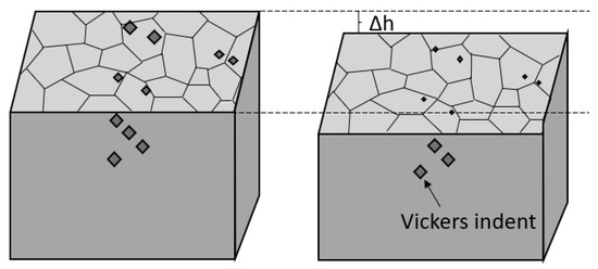
Figure 1.
Schematic of the sample to measure the depth of polishing by Vickers indents on the side.
The phenomenological theory of martensite crystallography [19,20] was used to calculate the SDD and habit plane (HP) of bainite [21,22]. In the bainitic transformation, the shape deformation matrix F is given by (R is the rigid body rotation matrix; B is the Bain deformation; S2 and S1 are lattice-invariant shears; I is the identity matrix; m is the magnitude of shape strain; d is SDD; n is HP). In the case that the HP is parallel to (h k h)γ, the HPs of twin-related variants (ex. V1 and V2 in [23]) are parallel. In this study, the HPs of twin-related variants appeared to be nearly parallel to each other. Therefore, the double shear model [20], which predicts the (5 7 5)γ, was applied. The HP was (0.497 0.711 0.497)γ and SDD was [−0.201 0.707 −0.678]γ, respectively.
3. Results and Discussion
3.1. Morphology of Bainitic Ferrite Formed at Prior Austenite Grain Boundaries
Figure 2a,b show the typical OM and SEM images of the BFs formed at PAGB, respectively. BFs formed on both sides of the PAGBs in feather-like shapes, which is reported as a typical microstructure of upper bainite [24,25,26].
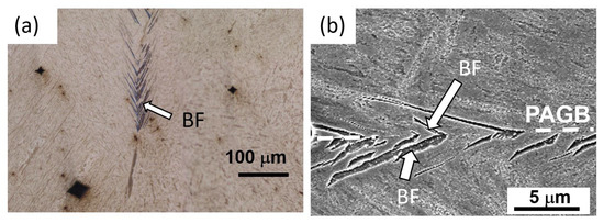
Figure 2.
Typical images of BF formed at PGGB by (a) OM and (b) SEM.
3.2. Effect of the Character of the Prior Austenite Grain Boundary on the Formation of Bainitic Ferrite
The character of the PAGB plane was analyzed from the perspectives of the misorientation between the PAGs (), the angle between the misorientation axis and the PAGB plane normal (), the crystal orientation of the PAGB plane, and the grain boundary energy. Figure 3 shows the relationship between the character of the PAGBs and the formation of BF. In this study, the analysis was mainly conducted in a square with 3000 × 3000 μm2. In this area, BFs were formed in nine out of 75 PAGBs (with an additional 12 twin boundaries). Some PAGBs cannot be analyzed because the PAGB planes were close to parallel to the polishing surface or the PAGB trace cannot be identified by the OM. To compare the character of the PAGBs where BFs were formed with the PAGBs where BFs were not formed, the PAGB where BFs were formed was additionally analyzed. The number of PAGBs where BFs were formed in this study was 21, and the number of PAGBs where BFs were not formed was 55 (twins are not included in this count). In Figure 3, the black circles and crosses correspond to the PAGB planes where BFs were formed and the PAGB where BFs were not formed, respectively. The distributions of and are shown in Figure 3a. It is reported that the BFs more preferentially form at the tilt boundaries [3]. Table 1 shows the numbers of tilt-like PAGBs ( > 45°) and twist-like PAGBs ( < 45°). In Table 1, the number of the tilt-like PAGBs where BFs were formed is bigger than that of the twist-like PAGBs where BFs were formed. The BFs were mainly formed from the tilt-like grain boundary in this study, as previously reported [3]. However, the numbers of tilt-like boundaries and twist-like boundaries are different. If the PAGB planes are randomly distributed, the probability P that is between and is given by
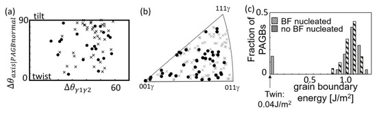
Figure 3.
(a) Distribution of and . (b) Inverse pole figure of the PAGB plane normal. Filled circle and cross correspond to the normal of the PAGB plane where BF forms and BF does not form. The blue plus corresponds to the HP normal. (c) Distribution of grain boundary energy of the PAGB where BF formed and the PAGB where BF did not form.

Table 1.
Numbers of the PAGBs where BFs were formed and the PAGBs where BFs were not formed at twist-like and tilt-like PAGBs and the fraction of twist-like PAGBs.
Using this calculation, the fraction of the twist-like PAGB is expected to be close to 0.3. From Table 1, the fraction of the twist-like PAGB in experiments is also approximately 0.3 for both PAGBs. Thus, it is suggested that the potency for BFs’ nucleation does not depend on the .
Figure 3b shows the inverse pole figure of the PAGB plane normal. The effect of the orientation of the PAGB plane on the formation of BF is considered to be small because the orientations of the PAGB planes where BFs form are randomly scattered. Figure 3c shows the distribution of grain boundary energies calculated using GB5DOF. The grain boundary energies of high-angle PAGBs observed in this study are 0.9–1.3 J/m2, and the grain boundary energy of the twin boundary is 0.04 J/m2. The formation of BFs at twin boundaries was not observed. It is suggested that one of the reasons for the suppression of BFs at twin boundaries is the lower grain boundary energy. In high-angle PAGBs, BFs formed at the PAGBs regardless of the grain boundary energies; thus, the values of , , and the grain boundary energy do not affect the formation of the BF.
3.3. Geometrical Relationship between the Bainitic Ferrite and the Prior Austenite Grain Boundary
The geometrical relationship between the BFs and the PAGB plane was investigated. Figure 4a shows an IPF map of the BFs and martensite. The EBSD orientation map with highlighted BFs and PAGs, and the corresponding (0 0 1)α pole figure of BFs (red) and martensite, are shown in Figure 4b,c, respectively. Figure 4d,e are the pole figures showing the geometrical relationship of PAGB plane and the trace of the PAGB plane in addition to important crystallographic planes and directions, such as CP, HP, CD, SDD, and <0 0 1>α in the sample coordinate system and the BF coordinate system, respectively. In Figure 4e, the axes of the pole figure are [0 0 1]α, [0 1 0]α, and [1 0 0]α of BF. [0 0 1]α, [0 1 0]α, and [1 0 0]α of BF are indexed so that CD is [1 −1 −1]α and CP is (0 1 1)α. In Figure 4e, the crystal orientation of the BF, such as CP, HP, CD, and SDD, are fixed, and the PAGB plane normal becomes a variable.
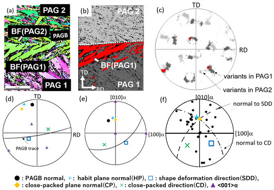
Figure 4.
(a) IPF map of BFs and martensite, (b) the corresponding EBSD orientation map with highlighted BFs (red) and martensite (martensite in PAG1: dark gray, martensite in PAG2: light gray), and (c) (0 0 1)α pole figure of BF (red) and the martensite in PAG 1 and PAG 2 (dark gray and light gray). The corresponding pole figure showing the directions and the normal of the planes of BF, normal of PAGB plane, and the trace of PAGB plane in (d) the sample coordinate system and (e) BF coordinate system. (f) Plots of the PAGB normals in the BF coordinate system. The plots represented by black circle: PAGB normal, light-blue plus: HP normal, blue square: SDD, orange diamond: CP normal, green cross: CD, dashed line: normal to SDD, and dashed–dotted line: normal to CD.
Figure 4f shows the geometrical relationship between the BFs and PAGB planes. In Figure 4f, the normals of PAGB planes are plotted in the reference frame of BF, as shown in Figure 4e. The axes are <0 0 1>α of BF, HP normal, CP normal, CD, SDD, and aggregates of the directions normal to CD and SDD (CD normal line, SDD normal line) are also plotted. The normal of PAGBs are relatively gathered around the HP normal. Since the HP is almost parallel to the CD and SDD, it was confirmed that the BFs whose CD and SDD are preferentially close to parallel to the PAGB plane form, as reported by the previous studies [3,4].
3.4. Crystal Orientation Relationship between the Bainitic Ferrite and the Adjacent Austenite Grain
The crystal orientation relationship between the BF and the adjacent PAG was investigated from the viewpoint of the near K-S rule. Figure 5 shows the distribution of the misorientation angle between the BF and the K-S OR in the adjacent PAG across the PAGB plane (). The is calculated by the following procedures. First, the crystal orientation of 24 variants in the adjacent PAG is calculated. Then, the misorientation between the BF and the variants in the adjacent PAG (~) was calculated. Finally, the minimum value in to is defined as . As shown in Figure 5, the values are smaller than 5° or 10° in 60% or 90% of BF, respectively. It is suggested that the BF with smaller is more likely to be formed. The BFs mainly formed on both sides of the PAGB planes, as shown in Figure 2. The orientation relationship between the BF and the BF in the adjacent PAG across the PAGB plane was investigated from the perspective of the misorientation angle between the BFs pair across the PAGB (). It is considered that the BFs can form with lower interfacial energy by having small .
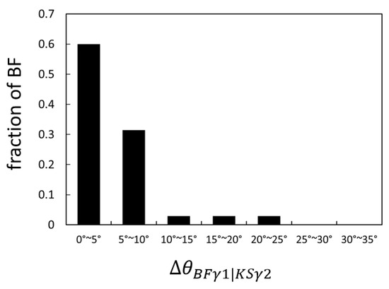
Figure 5.
Distribution of the misorientation angle between the BF and the K-S OR in the adjacent PAG ().
In the previous studies, if the , is smaller than 10°, the BF is considered to satisfy the near K-S rule [3,4]. The percentage of the BFs that satisfy the near K-S rule was 91% in this study, while the percentage of the BFs that satisfy the near K-S rule was 84% in Fe-0.15C-9Ni (wt%) steel transformed at 450 °C for 400 s. Although it was considered that the priority of the near K-S rule decreases because of the higher carbon content, the fraction of the BFs that satisfy the near K-S rule in this study is higher than the previous study despite the higher carbon content. This is considered to be due to the difference in the degree of transformation [3], and it is confirmed that the variant selection rules strongly works in relatively high carbon steels in the initial stage of transformation.
3.5. Crystal Orientation Relationship between the Bainitic Ferrite and the Bainitic Ferrite in the Adjacent Austenite Grain
In most cases, values are equal to values. Therefore, the variant pair whose misorientation across the PAGB forms. However, in some cases, the values of were larger than those of , as shown in Figure 6. Figure 6a shows the image quality map with the highlighted BFs pair, and Figure 6b shows the corresponding (0 0 1)α pole figure of the possible 24 variants of PAG 1 and PAG 2 according to the K-S OR. The of the red and blue BFs pair, which was formed at the PAGB in Figure 6a, is 8.5°, while the variant pair with smaller (7.2°) exists, as shown by the green and orange in Figure 6b. The BFs pair that has the smallest is not necessarily formed. Thus, other factors should be considered.
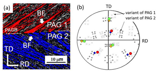
Figure 6.
(a) Image quality map with highlighted BFs and (b) (0 0 1)α pole figure of the variants calculated from the K–S orientation relationship. The BFs pair formed is shown in red and blue, the variants pair whose misorientation angle across the PAGB is the smallest is shown in green and orange, other variants of PAG 1 are shown in crosses, and other variants of PAG 2 are shown in diamonds.
3.6. Effect of the Shape Strain on the Formation of Bainitic Ferrite
It is reported that the shape strain affects the variant selection on the formation of martensite at PAGBs [6,7]. Regarding the formation of the martensite at both sides of the PAGB plane, some variant selection rules were proposed based on the geometrical relationship between the martensite and the martensite formed in the adjacent PAG from the perspective of the accommodation of the shape strain [6,7].
The first proposed mechanism is the accommodation of macroscopic shape strain. When the shape deformation matrix is close to the unit matrix, the increase in the elastic strain energy () is small. For example, it is reported that the macroscopic strain can be reduced when appropriate variants are formed at the PAGBs or in the PAGs. It is known that the average shape deformation matrix is close to the unit matrix when the six variants that compose the packet are formed in the PAGs [23,27]. It has been reported that when lenticular martensite formed on both sides of the tilt PAGB, the variants that reduced preferentially formed [6].
The second proposed mechanism focuses on the continuity of the shape strains at the interface of the different variants. The strain concentrates at the interface of the different variants because of the difference in the shape deformation [28]. The strain concentration is not favored because it is supposed to lead the increase in the strain energy. However, when the shape strain is continuous at the interface, the strain concentration and the increase in the strain energy can be suppressed. The continuity of shape strain has been studied in terms of the connectivity of each component [6,29] and the kinematic compatibility conditions (KC condition) [30,31]. It has been reported that the connectivity of each component is important in the slip transfer or cooperative nucleation of martensite [6,29]. The KC condition is satisfied for variant pairing of the lenticular martensite within PAGs [30]. The calculation methods for each condition are shown in the Appendix A.
The effect of the shape strain on the variant selection was investigated at the PAGBs where several variant pairs can satisfy < 10°. In this study, the number of PAGBs, where several variant pairs can satisfy < 10°, is 8. Table 2 shows the and calculated results of the shape strain from the perspectives of elastic strain energy (), , the shape deformation matrix of the variants in each PAG, and the solution of the KC condition of the variant pair that formed and the variant pair(s) that did not form at these PAGBs. In the case where the differences in are relatively small, while the differences in are relatively large (PAGB 1 and PAGB 2), variant pairs with a smaller are formed. The variant pairs with smaller are formed when the differences in and are small (PAGB 3). However, regarding PAGB 4, PAGB 5, and PAGB 6, the differences in , , and are small. It is difficult to find the differences between the variant pairs that were formed and the variant pairs that were not formed when focusing on the features considered in this study. The components of the shape deformation matrices of BFs are apparently different in PAGB 4, PAGB 5, and PAGB 6; thus, the connectivity of the strain does not seem to affect the variant selection of BF. In terms of the KC condition, the values of the rotation angle q, which is needed to satisfy the KC condition, in PAGB 4 and PAGB 5 are relatively small. However, to satisfy the KC condition, the junction plane and the PAGB plane must be parallel; thus, the KC condition is not satisfied at these PAGBs. Therefore, the KC condition also does not seem to affect the variant selection. In the case where differences in are relatively large (about 5° in this study) (PAGB 7 and PAGB 8), variant pairs with smaller were formed regardless of the shape strain, such as and other factors. By considering the effect of the shape strain, such as , , the connectivity of each component and the KC condition, on the variant selection, it is revealed that when the difference in between the variant pairs is relatively large, the variant pair with a smaller forms. On the other hand, when the difference in between the variant pairs is small, the variant pair that can reduce the preferentially forms.
Table 2.
Summary of the results of the crystal orientation of BF at PAGBs, where several BF pairs can form within 10° of misorientation. : misorientation angle of the BFs across the PAGB, : elastic strain energy, : angle between the SDD and PAGB, : shape deformation matrix of BF in the coordinate system in Figure A1, q: rotation angle of Q in the KC condition, : the angle between the junction plane and PAGB.
This study revealed that the BF forms on both sides of the PAGB, and the BF pair has small By examining the variant selection at PAGB, where several variant pairs can satisfy < 10°, it was also revealed that the or as well as the affect the variant selection of upper bainite.
4. Conclusions
A crystallographic analysis was conducted of the upper bainite formed at the PAGBs in Fe-0.6C-0.8Mn-1.8Si (in mass %) steel. First, the effect of PAGB character on the formation of BF were investigated from the perspective of the PAGBs character, such as misorientation, PAGB plane, and grain boundary energy.
BFs mainly form on both sides of the high-angle PAGBs, while BF formation was not observed at the twin boundary. The grain boundary energy of the twin boundary is quite low compared with typical high-angle PAGBs. It is suggested one of the reasons for the suppression of BF formation at twin boundaries is the lower grain boundary energy. There is no difference in the potency for BFs’ nucleation between the tilt-like PAGBs and twist-like PAGBs. In addition, the differences in the grain boundary energies, , and the orientation of the PAGB planes did not affect the formation of BF in high-angle PAGB.
The variant selection of BF was investigated from the perspective of the crystal and geometrical orientation relationship between the BF and the PAG or the BF across the PAGB from the perspectives of the , , KC condition, and so on. Though the BFs pair whose was small were formed to have low interfacial energy, the BF which has the smallest , was not necessarily formed.
When several variant pairs can satisfy small at a PAGB, the geometrical relationship between the BF and the BF in the adjacent PAG affect the variant selection of BF and the variant pair that can reduce the forms to accommodate the shape strain.
Author Contributions
Conceptualization, S.J. and S.N.; methodology, S.J. and S.N.; validation, S.J. and S.N.; formal analysis, S.J.; investigation, S.J.; resources, S.N.; data curation, S.J.; writing—original draft preparation, S.J.; writing—review and editing, S.N.; visualization, S.J.; supervision, S.N.; project administration, S.N.; funding acquisition, S.N. All authors have read and agreed to the published version of the manuscript.
Funding
This research was conducted as part of a project supported by JSPS KAKENHI (Grant Number 20H02475).
Data Availability Statement
The data are not currently available, since the data in this study will be used in our current research work.
Conflicts of Interest
The authors declare no conflict of interest.
Appendix A
Appendix A.1. Elastic Strain Energy [7,32]
The strain energy, , is calculated by the following equation:
where ; , G is the shear modulus of austenite, ν is Poisson’s ratio, and I is the identity matrix.
Appendix A.2. Connectivity of Each Component [6,29]
If the shape strain tensors, and , maintain the connectivity of the shape strain at the PAGB, the dilatation and shear components of the shape strain tensor against the PAGB should be equal. Therefore, when PAGB is parallel to (0 1 0), the strain components must satisfy the following equation:
In Table 2, to evaluate the connectivity of the shape strain, the shape strain tensors are represented in a specific coordinate system where the PAGB is parallel to (0 1 0), as shown in Figure A1. (To fix the coordinate system, the coordinate system is defined such that the z component of the SDD of BF in γ1 is 0.)

Figure A1.
Schematic of the coordinate system for the analysis in Table 2.
Figure A1.
Schematic of the coordinate system for the analysis in Table 2.

Appendix A.3. KC Condition [30,31]
Whether the shape deformation matrices of BFs () satisfy the KC condition (KC condition is sometimes referred to as Rank-1 connected) can be evaluated using the following equation:
In this equation, Q is the rotation matrix to satisfy the KC condition and is the JP. The rotation angle, q is calculated as . The any vector lying on the satisfies the following equation:
Therefore, the compatibility is satisfied on .
References
- Bhadeshia, H.K.D.H. Bainite in Steels: Theory and Practice; Maney Publishing: Leeds, UK, 2015. [Google Scholar] [CrossRef]
- Kurdjumov, G.; Sachs, G. Uber den Mechanismus der Stahlhartung. Z. Phys. 1930, 64, 325–343. [Google Scholar] [CrossRef]
- Furuhara, T.; Kawata, H.; Morito, S.; Miyamoto, G.; Maki, T. Variant Selection in Grain Boundary Nucleation of Upper Bainite. Metall. Mater. Trans. A 2008, 39, 1003–1013. [Google Scholar] [CrossRef]
- Kaneshita, T.; Miyamoto, G.; Furuhara, T. Variant selection in grain boundary nucleation of bainite in Fe-2Mn-C alloys. Acta Mater. 2017, 127, 368–378. [Google Scholar] [CrossRef]
- Archie, F.; Zaefferer, S. On variant selection at the prior austenite grain boundaries in lath martensite and relevant micro-mechanical implications. Mater. Sci. Eng. A 2018, 731, 539–550. [Google Scholar] [CrossRef]
- Ueda, M.; Yasuda, H.Y.; Umakoshi, Y. Effect of grain boundary on martensite transformation behaviour in Fe–32 at.%Ni bicrystals. Sci. Tech. Adv. Mater. 2002, 3, 171–179. [Google Scholar] [CrossRef]
- Ueda, M.; Yasuda, H.Y.; Umakoshi, Y. Controlling factor for nucleation of martensite at grain boundary in Fe-Ni bicrystals. Acta Mater. 2003, 51, 1007–1017. [Google Scholar] [CrossRef]
- Nagano, T.; Enomoto, M. Calculation of the interfacial energies between α and γ iron and equilibrium particle shape. Metall. Mat. Trans A 2006, 37, 929–937. [Google Scholar] [CrossRef]
- Hielscher, R.; Schaeben, H.J. A novel pole figure inversion method: Specification of the MTEX algorithm. Appl. Crystallogr. 2008, 41, 1024–1037. [Google Scholar] [CrossRef]
- Nyyssönen, T.; Isakov, M.; Peura, P.; Kuokkala, V.T. Crystallography, Morphology, and Martensite Transformation of Prior Austenite in Intercritically Annealed High-Aluminum Steel. Metall. Mater. Trans. A 2016, 49, 6426–6441. [Google Scholar] [CrossRef]
- Christian, J.W. The Theory of Transformations in Metals and Alloys; Pergamon: Oxford, UK, 2002. [Google Scholar] [CrossRef]
- Porter, D.A.; Easterling, K.E.; Sherif, M.Y. Phase Transformations in Metals and Alloys; CRC Press: Boca Raton, FL, USA, 2009. [Google Scholar] [CrossRef]
- Bulatov, V.V.; Reed, B.W.; Kumar, M. Grain boundary energy function for fcc metals. Acta Mater. 2014, 65, 161–175. [Google Scholar] [CrossRef]
- Olmsted, D.L.; Foiles, S.M.; Elizabeth, H.A. Survey of computed grain boundary properties in face-centered cubic metals: I. Grain boundary energy. Acta Mater. 2009, 57, 3694–3703. [Google Scholar] [CrossRef]
- Holm, E.A.; Olmsted, D.L.; Foiles, S.M. Comparing grain boundary energies in face-centered cubic metals: Al, Au, Cu and Ni. Scr. Mater. 2010, 63, 905–908. [Google Scholar] [CrossRef]
- Beladi, H.; Nuhfer, N.T.; Rohre, G.S. The five-parameter grain boundary character and energy distributions of a fully austenitic high-manganese steel using three dimensional data. Acta Mater. 2014, 70, 281–289. [Google Scholar] [CrossRef]
- Davey, W.P. Precision Measurements of the Lattice Constants of Twelve Common Metals. Phys. Rev. 1925, 25, 753. [Google Scholar] [CrossRef]
- Babu, S.S.; Specht, E.D.; David, S.A.; Karapetrova, E.; Zschack, P.; Peet, M.; Bhadeshia, H.K.D.H. In-situ observations of lattice parameter fluctuations in austenite and transformation to bainite. Metall. Mater. Trans. A 2005, 36, 3281–3289. [Google Scholar] [CrossRef]
- Bowles, J.S.; Mackenzie, J.K. The crystallography of martensite transformations I. Acta Metall. 1954, 2, 129–137. [Google Scholar] [CrossRef]
- Kelly, P.M. Crystallography of Lath Martensite in Steels. Mater. Trans. JIM 1992, 33, 235–242. [Google Scholar] [CrossRef]
- Komine, S.; Sekido, K.; Inoue, J. In-situ measurement of surface relief induced by Widmanstätten and bainitic ferrites in low carbon steel by digital holographic microscopy. Scr. Mater. 2019, 162, 241–245. [Google Scholar] [CrossRef]
- Swallow, E.; Bhadeshia, H.K.D.H. High resolution observations of displacements caused by bainitic transformation. Mater. Sci. Technol. 1996, 12, 121–125. [Google Scholar] [CrossRef]
- Morito, S.; Tanaka, H.; Konishi, R.; Furuhara, T.; Maki, T. The morphology and crystallography of lath martensite in Fe-C alloys. Acta Mater. 2003, 51, 1789–1799. [Google Scholar] [CrossRef]
- Tsuzaki, K.; Nakao, C.; Maki, T. Formation Temperature of Bainitic Ferrite in Si-Containing Steels. Mater. Trans. JIM 1991, 32, 658–666. [Google Scholar] [CrossRef]
- Oka, M.; Okamoto, H. Variation of Transition Temperatures from Upper to Lower Bainites in Plain Carbon Steels. J. Phys. IV 1995, 5, 503. [Google Scholar] [CrossRef]
- Ohtani, H.; Okaguchi, S.; Fujishiro, Y.; Ohmori, Y. Morphology and properties of low-carbon bainite. Metall. Trans. A 1990, 21, 877–888. [Google Scholar] [CrossRef]
- Nambu, S.; Shibuta, N.; Ojima, M.; Inoue, J.; Koseki, T.; Bhadeshia, H.K.D.H. In situ observations and crystallographic analysis of martensitic transformation in steel. Acta Mater. 2013, 61, 4831–4839. [Google Scholar] [CrossRef]
- Basak, A.; Levitas, V.I. Nanoscale multiphase phase field approach for stress-and temperature-induced martensitic phase transformations with interfacial stresses at finite strains. J. Mech. Phys. Solids 2018, 113, 162–196. [Google Scholar] [CrossRef]
- Livingston, J.D.; Chalmers, B. Multiple slip in bicrystal deformation. Acta Metall. 1957, 5, 322–327. [Google Scholar] [CrossRef]
- Shinohara, Y.; Akabane, S.; Inamura, T. Analysis of variant-pairing tendencies in lenticular martensite microstructures based on rank-1 connection. Sci. Rep. 2021, 11, 14957. [Google Scholar] [CrossRef]
- Bhattacharya, K. Microstructure of Martensite: Why It Forms and How It Gives Rise to the Shape-Memory Effect; OUP: Oxford, UK, 2003. [Google Scholar]
- Mura, T. Micromechanics of Defects in Solids; Springer: Dordrecht, The Netherlands, 1982. [Google Scholar]


Disclaimer/Publisher’s Note: The statements, opinions and data contained in all publications are solely those of the individual author(s) and contributor(s) and not of MDPI and/or the editor(s). MDPI and/or the editor(s) disclaim responsibility for any injury to people or property resulting from any ideas, methods, instructions or products referred to in the content. |
© 2023 by the authors. Licensee MDPI, Basel, Switzerland. This article is an open access article distributed under the terms and conditions of the Creative Commons Attribution (CC BY) license (https://creativecommons.org/licenses/by/4.0/).