Article

Study on the Microstructure and Mechanical Properties of Martensitic Wear-Resistant Steel

1
Shantui Construction Machinery Co., Ltd., Jining 272073, China
2
School of Mechanical Engineering, Qilu University of Technology (Shandong Academy of Sciences), Jinan 250353, China
3
Shandong Institute of Mechanical Design and Research, Jinan 250031, China
4
Shandong Sun Wearparts Co., Ltd., Jining 272000, China
*
Author to whom correspondence should be addressed.
Crystals 2023, 13(8), 1210; https://doi.org/10.3390/cryst13081210
Submission received: 10 July 2023 / Revised: 30 July 2023 / Accepted: 2 August 2023 / Published: 4 August 2023
(This article belongs to the Special Issue Microstructure and Mechanical Properties of Metallic Materials 2023)

Abstract

:
In order to improve the overall performance of edge plates such as bulldozer blades, composition and heat treatment processes were optimized on the martensitic wear-resistant steel grade 400 HB. Steel billets were first obtained through smelting in a state of hot rolling, followed by quenching and tempering to obtained wear-resistant steel (HB400). Then, HB400 was subjected to metallographic observation, electron backscatter diffraction (EBSD) testing, and transmission electron microscope (TEM) characterization and property testing. The results showed that HB400 exhibited microstructural refinement, characterized by narrower martensite laths and finer grains. The EBSD results indicated a uniform microstructure with a low content of the residual austenite (0.5%), indicating good hardenability. TEM observation of the martensite matrix revealed the presence of substructures, i.e., numerous dislocations in martensite laths. The average Rockwell hardness (HRC) of HB400 was 46.3, and the average Brinell hardness (HB) was 402. A mechanical properties test demonstrated comprehensive properties, which showed that the ultimate tensile strength and yield strength of HB400 were 1495 MPa and 1345 MPa, respectively, with a relative elongation of 12%. Friction and wear experiments showed that the friction coefficient and wear rate in reciprocating mode decreased by 16.1% and 45.4%, respectively, while in rotating mode, they decreased by 27.6% and 2.1%, respectively, as the load increased from 100N to 300N. According to the wear morphology, the main wear mechanisms were identified as adhesive wear, abrasive wear, and oxidative wear. The lubricating effect of the oxide layer generated by wear was identified as the primary reason for the reduction in the friction coefficient. The relationship between microstructures and properties was discussed based on grain refinement strengthening and dislocation strengthening.

1. Introduction

Edge plates of engineering machinery such as bulldozer blades, grader blades, and excavator bucket blades inevitably face the issue of frictional wear under service conditions [1,2]. The service lives of edge plates on engineering machinery are determined by their wear resistance. The research and development of large-scale construction machinery equipment shows that the existing products cannot meet the requirements, and the wear resistance needs to be further improved especially urgently. Frictional wear is influenced by various factors, but it typically occurs on the surface of materials [3]. Therefore, the wear resistance of the material itself is crucial. Enhancing the wear resistance of the material, ensuring its strength, and extending its service life are the primary concerns in the design, manufacturing, and use of engineering machinery edge plates.
High-strength, wear-resistant steel is developed based on low-alloy, high-strength weldable steel. It has good wear resistance and a service life several times that of traditional structural steel plates, and the production process is simple. Common types of wear-resistant steel include the Swedish Hardox series, the Japanese JFE series, the German DILLIDUR series, the Chinese NM series, etc. Among the different structures of wear-resistant steel, martensitic steel exhibits better wear resistance and has a certain toughness, making it suitable for high-wear environments [4]. Additionally, the production process of martensitic wear-resistant steel is relatively simple [5]. Therefore, the majority of these wear-resistant steels are based on the martensitic microstructure [6].
The wear resistance of martensitic steel depends on the martensite structure obtained through quenching, and martensitic steel with better hardenability has better wear resistance. Traditional martensitic steel contains high-cost elements (Cr, Ni, and Mo) and rapid cooling to ensure hardenability, which increases production costs [7]. Researchers have attempted to reduce costs by partially replacing high-cost elements with low-cost ones. For example, Calcagnotto et al. found that the addition of low-cost Mn significantly improved the hardenability, strength, and wear resistance of martensitic wear-resistant steel [7]. A medium-Mn quenching system can effectively replace the traditional Cr–quenching. Steel plates were tempered at 450℃, and the holding time was 80 min, subsequently air–cooled. Ni and Cr–Mo quenching systems shortened the production process [8]. In addition, other elements such as Al, Cu, and Ti also contributed to improved hardenability, as has been validated in austenitic steel [9]. The addition of Ti and Al to low-carbon martensitic stainless steel (MSS) has also shown good results [10]. These studies provide references for the research on martensitic steel in this study.
Besides wear, recent studies have shown that martensitic steel is prone to cracking under cyclic loading [6]. Therefore, another strategy for improving the overall performance of martensitic steel is to optimize the heat treatment process to obtain fine-grained structures that are favorable for toughness [11]. For example, the use of induction quenching generates a hardened region with high hardness and high compressive stress, which benefits the mechanical properties of the components by increasing fatigue strength and wear resistance [12,13]. However, induction quenching tends to cause excessive austenite grain growth or residual stress [14]. Therefore, further treatment is needed for the samples after induction quenching. Tempering after quenching can effectively eliminate residual stress [15]. Deng et al. performed tempering at medium-to-low temperatures on conventionally quenched martensitic steel, resulting in excellent wear resistance as well as high strength and toughness [16]. Therefore, for martensitic wear-resistant steel, the method of induction quenching followed by tempering at medium-to-low temperatures may be feasible.
In this study, based on low-cost consideration, we aimed to obtain martensitic wear-resistant steel (HB400) with high strength by optimizing the composition and heat treatment processes. The microstructure and corresponding mechanical properties of HB400 were analyzed through the strengthening mechanism and Archard wear law. Through this study, we hope to extend the service lives of the relevant products and to further expand its application scope.

2. Material and Methods

The composition of wear-resistant steel in this study was designed according to the composition of Hardox400, which is shown in Table 1. The content of Cr elements was reduced, while Al, Ti, and Cu elements were added. The steel was smelted in a converter with a nominal capacity of no less than 120 tons. The subsequent process outside the furnace consisted of vacuum degassing and refining. Then, continuous casting and rolling were carried out, resulting in steel plates with thicknesses of 30 mm.
Steel plates underwent heat treatment, which consisted of high-temperature quenching followed by tempering at medium-to-low temperatures. During the heating process, a reciprocating heating technique was used to ensure uniform temperature distribution. The temperature detection in the core of the steel plates during the heating process is shown in Figure 1a. Compared with the traditional heating method, the reciprocating heating technology enhanced the speed of heating up the steel plate and improved the temperature uniformity in the core of the steel plates. Steel plates were heated to 880 °C, held for 80 min, and then water–cooled. Induction quenching technology was employed to adjust and control the cooling rate according to the specific dimensions of the plates, aiming to achieve a uniform microstructure and mechanical properties. As shown in Figure 1b, core hardness tests after quenching showed better hardenability of induction quenching compared to traditional quenching. After quenching, the steel plates were tempered at 450 °C, the holding time was 80 min, and they were air–cooled.
After heat treatment, steel plates were cut into small pieces with dimensions of 5 × 5 × 10 mm. The samples marked HB400 were first milled using sandpaper, then polished using a polishing machine with model MP-2A to achieve a smooth and scratch-free surface. A metallographic sample was prepared by etching with a 4% nitric acid alcohol solution. The crystal orientation of HB400 was analyzed using electron backscatter diffraction (EBSD) (EDAX Inc. of Tokyo, Japan) with the model EDAX Velocity Super. The collected voltage was set at 20 kV, and the crystal orientations, including RD (rolling direction), ND (normal direction), and TD (transverse direction), were determined. The microstructure was analyzed using a transmission electron microscope (TEM) (FEI Company of Hillsboro, OR, USA) with the model FEI Talos 200× and an acceleration voltage of 200 kV. TEM samples were prepared with a twin-jet electropolishing device, using a 5% ethanolic perchloric acid solution as the etchant. The voltage was set at 25–28 V, and the temperature was −20 °C.
Hardness tests were conducted using a Brinell hardness tester (Taiming Optical Instrument Co., Ltd. of Shanghai, Shanghai, China) and a Rockwell hardness tester (Taiming Optical Instrument Co., Ltd. of Shanghai, Shanghai, China). Tensile tests were performed using an electronic universal testing machine, model WDW-300E. The tensile rate was set at 0.5 mm/min. Friction–wear tests (Bruker Company of Baden-Württemberg, Ettlingen, Germany) were conducted using a friction tester with the model UMT-3. The upper friction pair was a GCr15 steel ball with a diameter of 6 mm, and the lower friction pair was the sample, in the form of a circular disc with a diameter of 55 mm and a thickness of 10 mm. Before the friction–wear tests, we first used 800#, 1000#, 1200#, and 1500# sandpaper to polish the experimental surface of the sample. Then, we used a polishing machine (model MP-2A) for polishing until the experimental surface became bright and free of scratches. During the polishing process, we used a polishing solution of SiO2 with a particle size of 0.5 µm. The tests were conducted at room temperature under dry friction conditions. The detailed parameters are shown in Table 2. The sliding distance in reciprocal and rotation modes was 24 m and 125.6 m, respectively. The volume of wear and the three-dimensional images were obtained using a white light interferometer (Bruker company of Baden-Württemberg, Ettlingen, Germany), model Bruker Contour GT–K 3D.
After the tensile and friction–wear tests, a scanning electron microscope (SEM) was used to observe the fracture surfaces and wear scars to analyze the fracture types and the extent of wear, respectively.

3. Results and Discussion

3.1. Microstructure

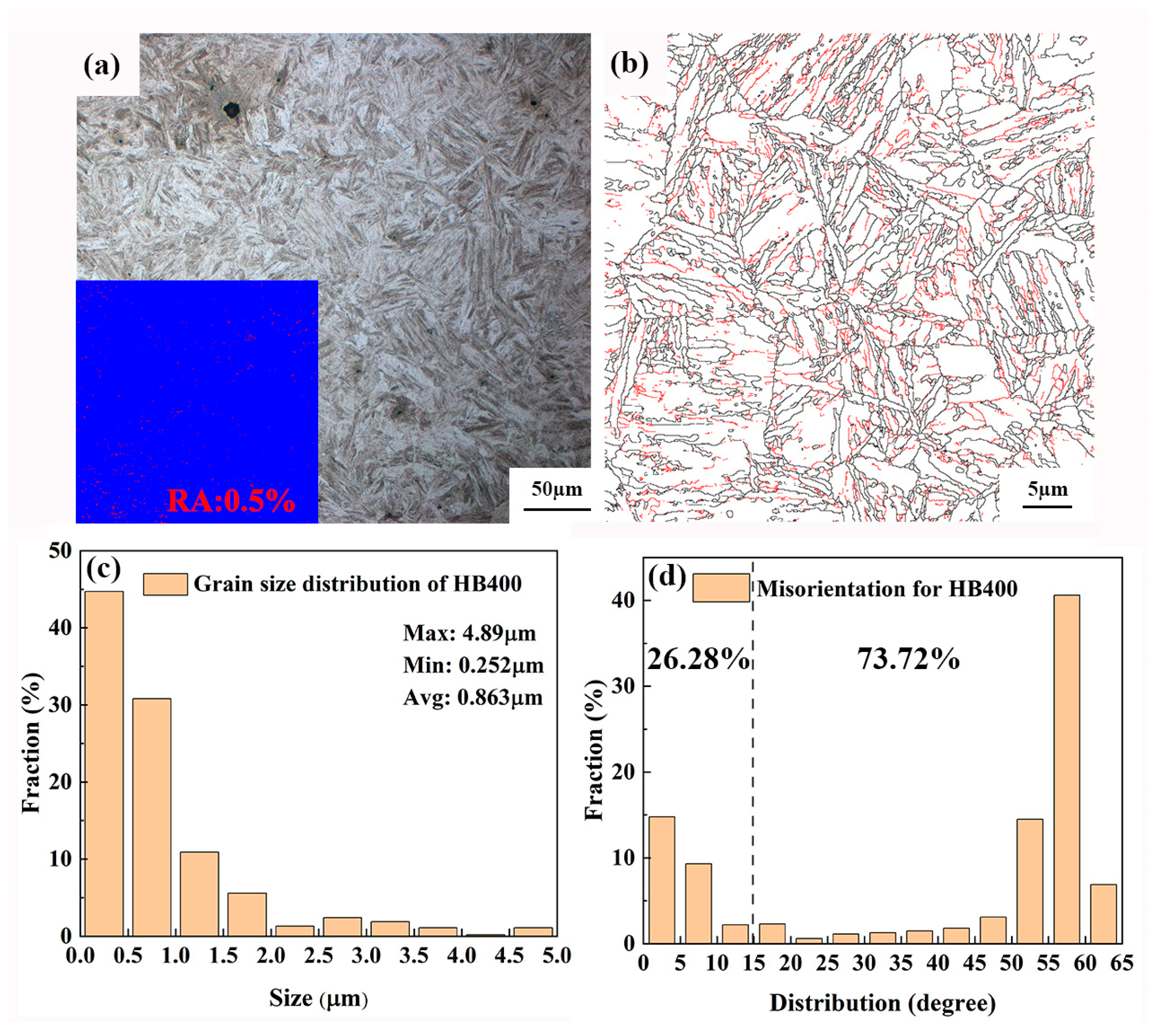
The performance of wear-resistant steel is usually determined by the martensitic microstructure obtained through phase transformation [17]. As shown in Figure 2a, the metallographic structure of wear-resistant steel in this study obtained after heat treatment consisted of lath-shaped martensite with fine grains. In addition, the content of retained austenite (RA) was only 0.5%, indicating good hardenability of the experimental steel. Figure 2b displays the grain boundaries of wear-resistant steel, among which the red and black lines indicate low-angle and high-angle grains, respectively. Figure 2c presents the statistical analysis of average grain size, showing that the majority (75.5%) of the grains had sizes smaller than 1 µm. The largest grain size was 4.83 µm, while the smallest grain size was 0.252 µm, with an average size of 0.863 µm, indicating a small grain size. Figure 2d shows the analysis results of misorientation angles, indicating a content of 26.28% and 73.72% for low-angle and high-angle grain boundaries, which correspond with Figure 2b. Actually, the low-angle grain boundaries represent dislocations, which will be discussed in microstructure of TEM.
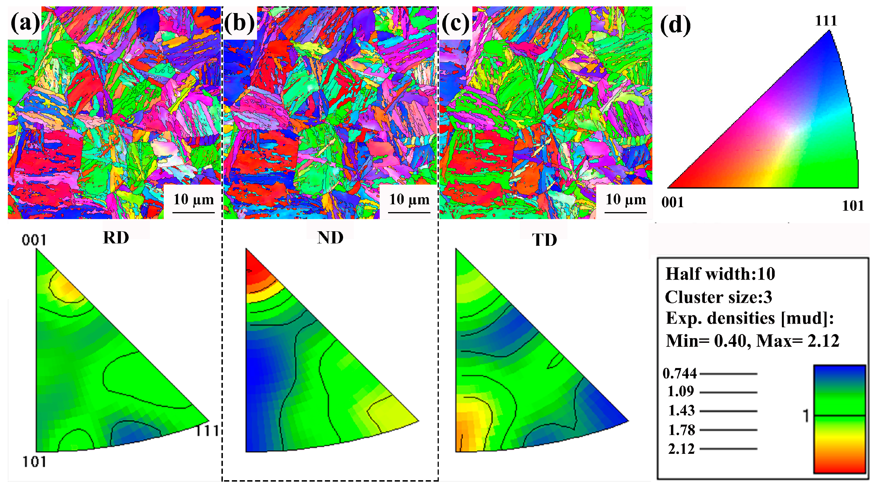
Figure 3 illustrates the inverse pole figures (IPFs) of wear-resistant steel with grain boundaries in the RD, TD, and ND. The colors in Figure 3a–c represent crystal orientations perpendicular to the observed planes in these regions, as depicted by the solid triangular shapes in Figure 3d, while the light black dashed lines represent boundaries between substructures. There was a weak texture present, and the overall microstructure was relatively homogeneous. It can be observed that multiple fine martensite laths combined to form martensite laths, and under all three orientations, the martensite laths were fine, indicating good hardenability.
The microstructure of HB400 was further characterized using TEM at higher magnification, and the results are shown in Figure 4. In the bright-field image (Figure 4a, g3g mode), the martensite laths contained a high density of dislocations, indicated by yellow arrows. The dislocations were characterized using Image J software. A total of about 60–100 dislocations were counted in 3–5 regions to evaluate the density of the dislocations. The statistical results indicated that the density of the dislocations was 1.63 × 10¹⁵/m2. The selected area electron diffraction (SAED) results indicated a single-phase region in this area. In certain regions, polygonal phases appeared, as shown in Figure 4b, with a diameter of 100 nm. SAED confirmed that this region was multiphased. Subsequently, element distribution of this region was performed, as shown in Figure 4(b1–b12), revealing that the primary elements of the polygonal phase were C, N, P, and S. Based on this, it can be inferred that this phase represents inclusions [18].

3.2. Mechanical Performance Test

3.2.1. Hardness Test

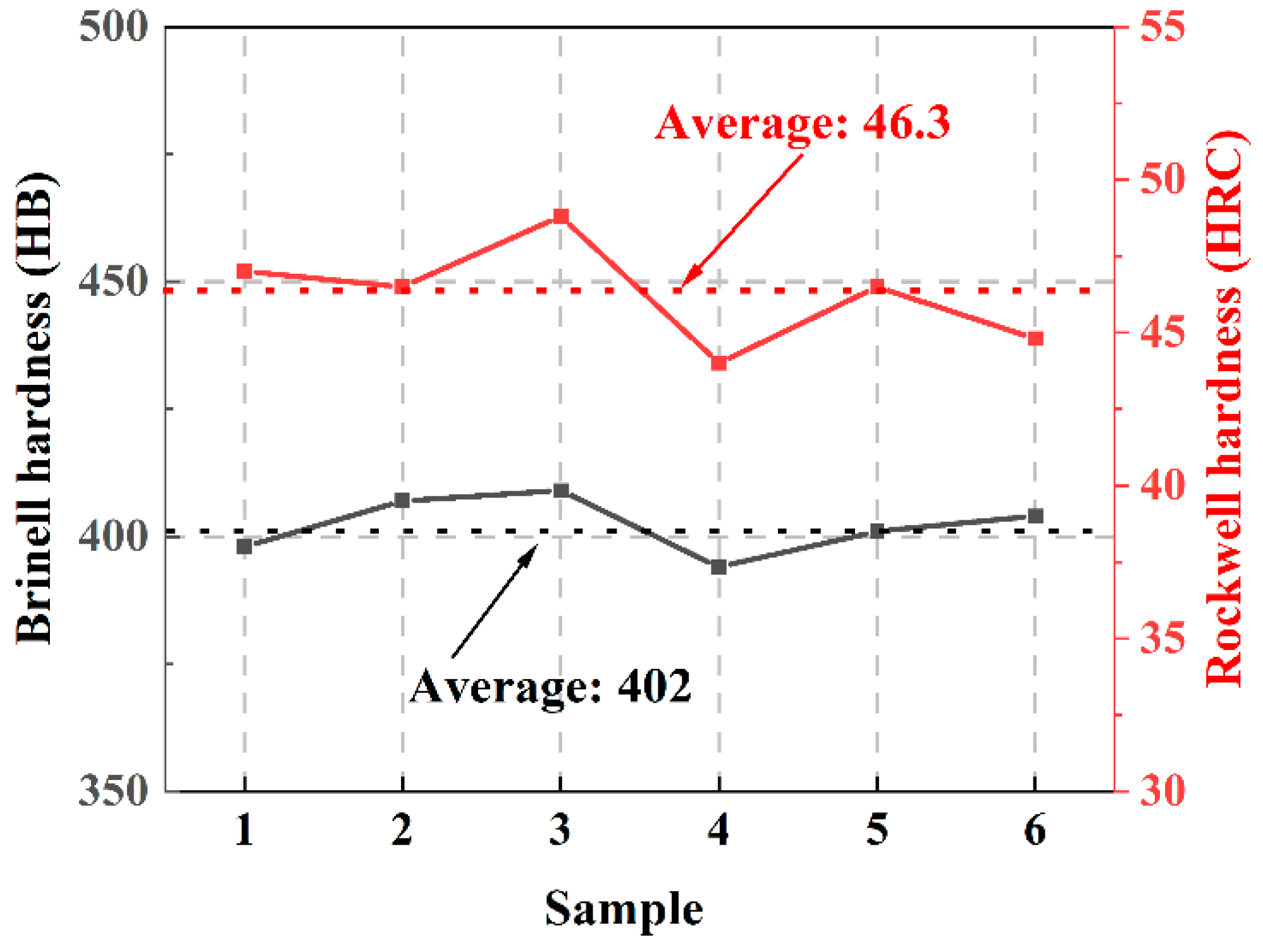
The results of Brinell hardness (HB) and Rockwell hardness (HRC) for HB400 are shown in Figure 5. The average HB of HB400 was 402, and the average HRC was 46.3.

3.2.2. Tensile Properties

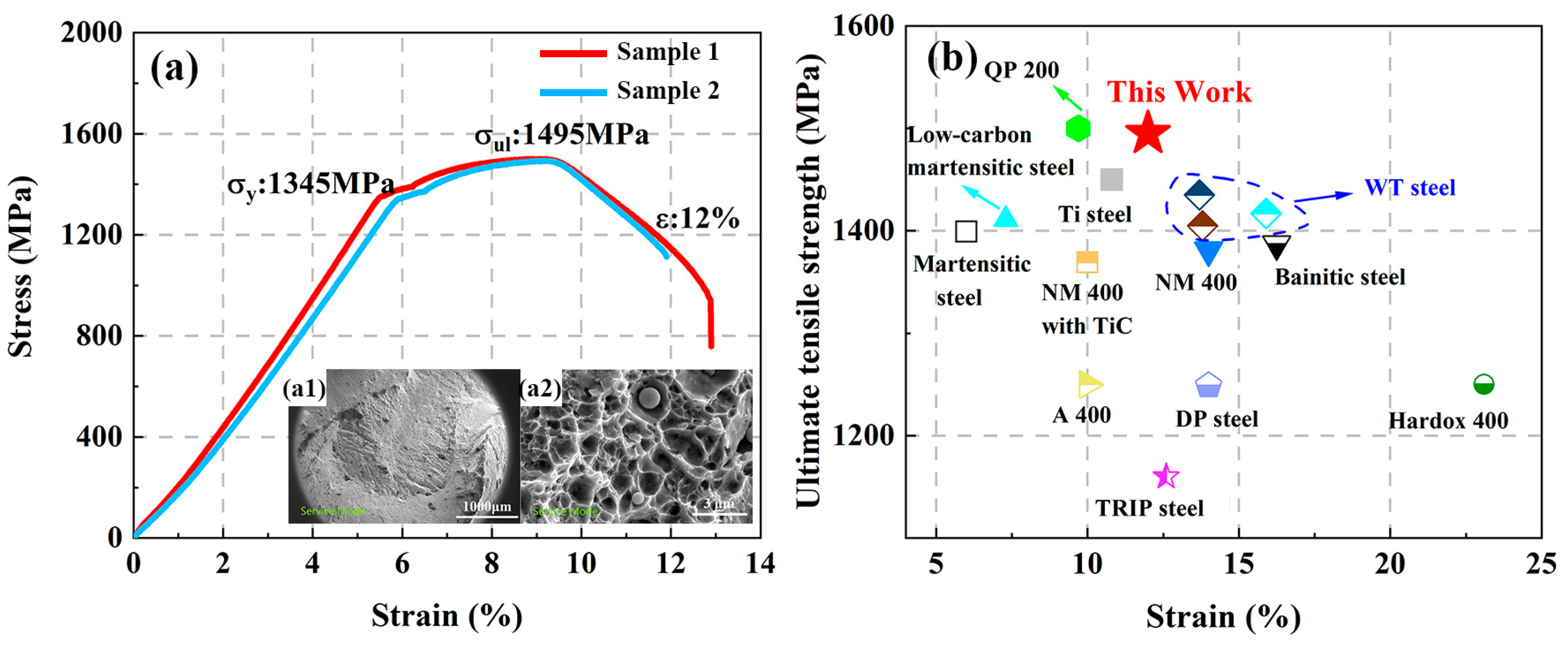
Figure 6a presents the stress–strain curve of HB400, with an average yield strength of 1345 MPa, an average ultimate tensile strength of 1495 MPa, and a relative elongation of 12%. Figure 6(a1,a2) show the macroscopic and microscopic morphologies of the tensile fracture surface of wear-resistant steel, respectively. In Figure 6(a1), it can be observed that the central region of the fracture surface exhibited evident necking and a typical toughness fracture surface composed of a fibrous zone and a shear lip zone, representing crack initiation and shear fracture, respectively. Figure 6(a2) is a high-magnification view of the central region in Figure 6(a1), where dimples can be observed. The direction of the dimples coincided with the direction of the applied stress. Under tensile conditions, the size of the dimples was uneven, with larger and deeper dimples formed by spherical particle distribution. This indicates the occurrence of plastic deformation before fracture. The presence of small cavities suggests rapid nucleation of voids, resulting in failure. Figure 6b compares the ultimate tensile strength and elongation of HB400 with steel grades of 400 HB. The optimized HB400 martensitic wear-resistant steel in this study demonstrated better comprehensive properties in terms of ultimate tensile strength and elongation [6,19,20,21,22,23,24,25,26,27]. The main reason for the material dominated by the martensitic phase in this study having a relative elongation of 12% is the refinement of the grain size and the appropriate tempering process. First, the addition of elements such as Al, Cu, and Ti helps to prevent excessive grain growth, resulting in grain refinement [9]. Secondly, the application of induction quenching technology effectively enhances the cooling rate, leading to a fine-grained microstructure. Additionally, the tempering process after quenching can eliminate residual stresses and balance the strength and toughness [11]. Lastly, in this study, the material dominated by the martensitic phase had a relative elongation of 12%.

3.2.3. Wear Resistance Test

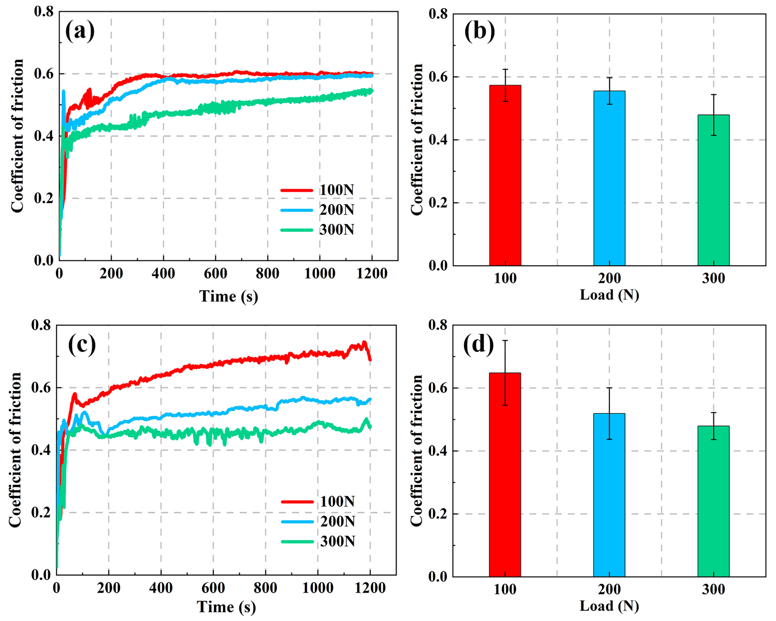
The coefficient of friction is an important indicator of wear-resistant materials. Figure 7 depicts the curve of the coefficient of friction over time for HB400 in reciprocal and rotation modes. The coefficient of friction is influenced by the state of the friction pairs. At the initial stage of friction, the contact between the friction pairs is mainly point contact, resulting in lower friction resistance and a smaller coefficient of friction. As the friction pairs continuously wear and detach during the friction process, the point contact transitions into surface contact, increasing the actual contact area and rapidly increasing the coefficient of friction, as shown in Figure 7a,c. This stage is relatively short, and after approximately 1 min, the coefficient of friction enters the running-in stage. In this stage, the effective contact area between the friction pairs further increases, leading to an increase in the number of abrasive particles and intensifying abrasive wear. Finally, under the combined effects of frictional heat, surface oxidation, and surface hardening, the generation and overflow of abrasive particles reaches a stable state, and the coefficient of friction tends to stabilize [28]. Figure 7b,d indicate that the average coefficient of friction for HB400 in both modes does not increase with increasing load; instead, it decreases.
The wear track profiles under different loads in the reciprocal and rotation modes are shown in Figure 8a,c. With increasing load, both the depth and the width of the wear tracks increased. At a load of 300 N, the wear track reached its maximum depth, measuring 103 μm and 35 μm, respectively. Compared to the reciprocal mode, the rotation mode exhibited protrusions and deformed regions on the inner side. This can be attributed to the greater force exerted on the inner side compared to the outer side during the wear process in rotation mode, resulting in the accumulation of debris formed by the squeezing between the friction pairs. The wear volume under both modes was calculated and is presented in Figure 8b,d. The wear volume also increased with the increasing load, but the increase was not proportionate. The wear volumes under a load of 300 N in both the reciprocal and rotation modes almost ceased to increase compared to the load of 200 N.
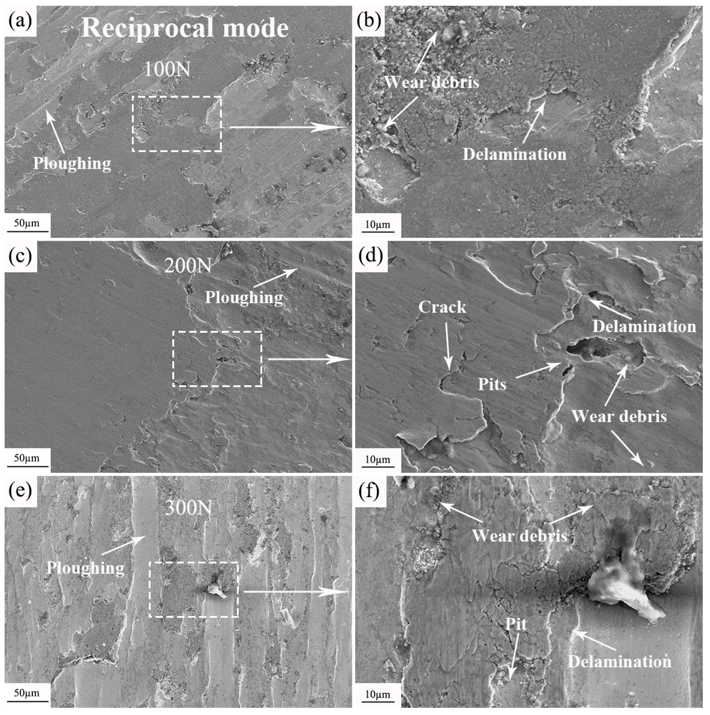
To analyze the reasons for the decrease in the friction coefficient and the slowdown of wear volume growth, the worn surfaces were examined. Figure 9 displays the morphologies of the worn surfaces of HB400 under different loads in the reciprocal mode. As shown in Figure 9a,c,e, all three load conditions resulted in ploughing grooves. The direction of the ploughing grooves was consistent with the direction of wear, and their number increased with the increasing load. The formation of plowing grooves was attributed to the plowing effect between GCr15 and the larger wear particles generated during the wear process. In other words, the abrasive particles wore down the surface. With higher loads, more wear particles were generated, leading to a greater number of plowing grooves.
Figure 9b,d,f are the magnified views of selected areas in Figure 9a,c,e, respectively. Wear particles, some of which may be oxides, were found under all three load conditions [29]. These wear particles, along with the oxides, accumulate and form an oxide layer. The frictional heat generated during wear causes adhesion between the wear particles and oxides, resulting in their accumulation on the material surface. The oxide layer formed after accumulation exhibits weak bonding to the substrate and subsequently detaches during subsequent wear, exposing the material’s surface. Then, a new oxide layer forms, and this cycle continues until wear is stopped [29]. Under higher load conditions, the formation and detachment of the oxide layer occur more frequently. The detached oxide layer acts as a lubricant, corresponding to a lower friction coefficient under high loads [30]. This situation can also be observed in the impact abrasive wear experiments of martensitic steel, where martensitic steel demonstrates better wear resistance under higher impact energy [6]. In addition to the detachment of the oxide layer, the formation of dislocation walls during the wear process also contributes to the wear resistance under high loads [26]. Similarly to impact abrasive wear, cracks and pits were observed under the load conditions of 200 N and 300 N, indicating fatigue wear. The cracks were connected to the pits, leading to surface material spalling. The spalled surface material also exhibits the lubricating effect of the oxide layer. Under the reciprocating mode, the wear mechanisms at a load of 100 N included abrasive wear, oxidative wear, and adhesive wear. With increasing load, fatigue wear was also observed under conditions of 200 N and 300 N.
Figure 10 depicts the morphologies of the worn surfaces of HB400 in the rotation mode. In contrast to the reciprocal mode, no significant plowing grooves were found under the loads of 100 N and 200 N. However, ploughing grooves were observed under a load of 300 N, indicating the occurrence of abrasive wear. After magnifying and observing typical areas under each load condition, it was found that the oxide layer formed by wear particles and oxides increased with the increasing load. However, compared to the oxide layers generated in the reciprocal mode, the oxide layers in the rotation mode were fewer and smaller.
The wear rate can reflect the wear under different loads [31]. The wear rate can be obtained using Archard’s wear law. According to the equation for the wear rate [31]:
W = V N L
where W represents the wear rate, V is the wear volume, N is the applied load, and L is the total sliding distance. The calculation results are summarized in Figure 10. The wear rate in the reciprocal mode is shown in Figure 11a. As the load increased, the wear rate decreased. At 300 N, the wear rate was 2.39 × 10⁻⁵ mm3N−1m−1, which is a 45.4% decrease compared to the wear rate of 4.38 × 10⁻⁵ mm3N−1m−1 at 100 N. This corresponds to a decrease in the friction coefficient and a slowdown in the wear volume growth. The wear rate in the rotation mode is shown in Figure 11b, where the wear rate is generally lower compared to the reciprocal mode. The highest wear rate was observed under a load of 200 N, reaching 1.47 × 10⁻⁶ mm3N−1m−1, and at 300 N, it decreased to 1.09 × 10⁻⁶ mm3N−1m−1, which is a 25.8% decrease. There were fewer friction and wear experiments under a 100–300 N load. By comparing the experimental results of 400 HB-level wear-resistant steel, antibacterial stainless steel, and austempered ductile iron (ADI) [32,33,34,35], it was found that HB400 has a lower wear rate, indicating better wear resistance.
The discussion on wear rate needs to be combined with the microstructure. The wear rate is influenced by the martensitic structure, such as the density of dislocations and the size of the laths [36,37]. During the process of induction hardening, austenite rapidly undergoes a phase transformation into martensite, forming numerous new martensite nuclei and growth. During the subsequent tempering process, the growth rate of martensite grains is slow due to the low tempering temperature [10,11]. In addition, the added Al, Ti, and Cu have the effect of inhibiting grain growth [38,39]. The solid solution-strengthening effect of Al and Cu elements can enhance the hardness of the alloy, increase the energy of grain boundaries, and promote grain boundary migration, thereby helping to refine the size of martensite grains [11]. The addition of Ti elements may promote the redistribution of carbon during the martensite phase transformation process. Ti combines with carbon to form TiC particles, reducing the carbon content. These particles can act as obstacles to pin dislocations and impede grain growth, resulting in grain refinement. Fine grains can reduce a material’s microstructural defects and surface roughness, thereby improving its wear resistance [40].
The strengthening effect of dislocations follows the Taylor hardening model [41]:
σ ρ = m α G b ρ 0.5
where m is the average Taylor factor (about 2.1 for martensitic [41]), α is the constant associated with the crystal structure (about 0.17), G is the shear modulus (81,600 MPa for steels), b is the Burgers vector, 0.248 nm [42], and ρ is the dislocation density 1.63 × 10¹⁵/m2. The calculated dislocation strengthening of HB400 is 291.9 MPa. During dry friction, the density of these dislocations further increases, causing their accumulation along grain boundaries. The accumulation of dislocations leads to an increase in local hardness, thereby enhancing the material’s wear resistance [38,43].
The grain refinement strengthening can be calculated using the Hall–Patch formula [42]:
σ g = k y d 1 / 2
where ky =  0.55 MPa·m−1/2 [37,43] and d represents the grain size, m. The increment of refinement strengthening in HB400 was 592 MPa.
The results indicate that grain refinement contributes to strengthening mechanisms. In this study, element adjustment and induction quenching followed by tempering can effectively refine the martensite structure, thereby increasing the increment of grain refinement strengthening. The smaller martensite grains have a higher dislocation density internally to accommodate plastic deformation, resulting in higher dislocation strengthening within HB400.

4. Conclusions

The aim of this study was to investigate the tempered martensitic wear-resistant steel HB400 after composition adjustment and heat treatment process optimization. By observing the microstructure and conducting mechanical property tests, the relationship between the microstructure, mechanical properties, and friction response of HB400 was analyzed. The main conclusions of this work are as follows:
(1)
The optimized HB400 exhibited finer grains, a uniform distribution of martensite laths, and a residual austenite content of only 0.5%. Additionally, higher-density dislocation loops were observed within the martensite laths.
(2)
In the mechanical property tests of HB400, the hardness met the standard requirements. The grain refinement and dislocation strengthening contributed to the improvement of tensile strength and yield strength.
(3)
Under loads ranging from 100 to 300 N, the wear resistance of HB400 increased with the increasing load. When the load reached 300 N, the growth of wear volume in HB400 slowed down, and the lubricating effect of the peeled oxide layer reduced wear, thereby enhancing the wear resistance of HB400 under high loads.

Author Contributions

Conceptualization and methodology, J.L., S.J. and S.Z.; validation, S.J., S.Z. and X.Z.; formal analysis, S.L.; investigation, S.Z. and X.Z.; data curation, Y.S.; writing—original draft preparation, S.J. and S.Z.; writing—review and editing, J.L. and S.J.; visualization, Y.X.; supervision, J.L.; project administration, W.L. and C.W. All authors have read and agreed to the published version of the manuscript.

Funding

This work was supported by Shandong Province Science and Technology-driven Small and Medium-sized Enterprises Innovation Capacity Enhancement Project (No. 2022TSGC2411) and Shandong Construction Machinery Intelligent Equipment lnnovation & Entrepreneurship Community Major Projects (No. GTT202110, No. GTT20220209).

Data Availability Statement

Not applicable.

Conflicts of Interest

The authors declare no conflict of interest.

References

  1. Xu, X.J.; Xu, W.; Ederveen, F.H.; Zwaag, S.V. Design of low hardness abrasion resistant steels. Wear 2013, 301, 89–93. [Google Scholar] [CrossRef]
  2. Rendón, J.; Olsson, M. Abrasive wear resistance of some commercial abrasion resistant steels evaluated by laboratory test methods. Wear 2009, 267, 2055–2061. [Google Scholar] [CrossRef]
  3. Muley, A.V. Wear and friction (Tribological) characteristic of aluminum based metal matrix hybrid composite: An overview. Mat. Today Proc. 2023. [Google Scholar] [CrossRef]
  4. Haiko, O.; Somani, M.; Porter, D.; Kantanen, P.; Kömi, J.; Ojala, N.; Heino, V. Comparison of impact-abrasive wear characteristics and performance of direct quenched (DQ) and direct quenched and partitioned (DQ&P) steels. Wear 2018, 400–401, 21–30. [Google Scholar]
  5. Haiko, O.; Valtonen, K.; Kaijalainen, A.; Uusikallio, S.; Hannula, J.; Liimatainen, T.; Kömi, J. Effect of tempering on the impact-abrasive and abrasive wear resistance of ultra-high strength steels. Wear 2019, 440–441, 203098. [Google Scholar] [CrossRef]
  6. Valtonen, K.; Ojala, N.; Haiko, O.; Kuokkala, V. Comparison of various high-stress wear conditions and wear performance of martensitic steels. Wear 2019, 426–427, 3–13. [Google Scholar] [CrossRef]
  7. Calcagnotto, M.; Ponge, D.; Raabe, D. On the Effect of Manganese on Grain Size Stability and Hardenability in Ultrafine-Grained Ferrite/Martensite Dual-Phase Steels. Met. Mater. Trans. A 2012, 43, 37–46. [Google Scholar] [CrossRef]
  8. Haiko, O.; Pallaspuro, S.; Javaheri, V.; Kaikkonen, P.; Ghosh, S.; Valtonen, K.; Kaijalainen, A.; Kömi, J. High-stress abrasive wear performance of medium-carbon direct-quenched and partitioned, carbide-free bainitic, and martensitic steels. Wear 2023, 526–527, 204925. [Google Scholar] [CrossRef]
  9. Lai, Z.H.; Sun, Y.H.; Lin, Y.T.; Tu, J.F.; Yen, H.W. Mechanism of twinning induced plasticity in austenitic lightweight steel driven by compositional complexity. Acta Mater. 2021, 210, 116814. [Google Scholar] [CrossRef]
  10. Derazkola, H.A.; García Gil, E.; Murillo-Marrodán, A.; Méresse, D. Review on Dynamic Recrystallization of Martensitic Stainless Steels during Hot Deformation: Part I—Experimental Study. Metals 2021, 11, 572. [Google Scholar] [CrossRef]
  11. Derazkola, H.A.; Garcia, E.; Murillo-Marrodán, A.; Hardell, J. The effect of temperature and strain rate on the mechanical properties and microstructure of super Cr13 martensitic stainless steel. JMRT 2023, 24, 3464–3476. [Google Scholar] [CrossRef]
  12. Zhong, H.L.; Wang, Z.; Gan, J.; Wang, X.L.; Yang, Y.; He, J.X.; Wei, T.T.; Qin, X.P. Numerical simulation of martensitic transformation plasticity of 42CrMo steel based on spot continual induction hardening model. Surf. Coat. Technol. 2020, 385, 125428. [Google Scholar] [CrossRef]
  13. Coupard, D.; Palin-luc, T.; Bristiel, P.; Ji, V.; Dumas, C. Residual stresses in surface induction hardening of steels: Comparison between experiment and simulation. Mater. Sci. Eng. A 2008, 487, 328–339. [Google Scholar] [CrossRef] [Green Version]
  14. Areitioaurtena, M.; Segurajauregi, U.; Fisk, M.; Cabello, M.J.; Ukar, E. Numerical and experimental investigation of residual stresses during the induction hardening of 42CrMo4 steel. Eur. Mech. J. A/Solids 2022, 96, 104766. [Google Scholar] [CrossRef]
  15. Rathinasuriyan, C.; Karthik, K.; Udhayaraj, S.; Bishwakarma, S. Investigation of induction hardening on heat-treated EN8 steel by alternately timed quenching process. Mat. Today Proc. 2023. [CrossRef]
  16. Deng, X.T.; Fu, T.L.; Wang, Z.D. Epsilon carbide precipitation and wear behaviour of low alloy wear resistant steels. Mater. Sci. Technol. 2016, 32, 320–327. [Google Scholar] [CrossRef]
  17. Clarke, A.J.; Miller, M.K.; Field, R.D.; Coughlin, D.R.; Gibbs, P.J.; Clarke, K.D.; Alexander, D.J.; Powers, K.A.; Papin, P.A.; Krauss, G. Atomic and nanoscale chemical and structural changes in quenched and tempered 4340 steel. Acta Mater. 2014, 77, 17–27. [Google Scholar] [CrossRef]
  18. Li, J.; Qiu, H.; Zhang, X.F.; Yu, H.L.; Yang, J.J.; Tu, X.H.; Li, W. Effects of (Ti, Mo) C particles on the abrasive wear-corrosion of low alloy martensitic steel. Wear 2022, 496–497, 204288. [Google Scholar] [CrossRef]
  19. Mondal, J.; Das, K.; Das, S. An investigation of mechanical property and sliding wear behaviour of 400Hv grade martensitic steels. Wear 2020, 458–459, 203436. [Google Scholar] [CrossRef]
  20. Kostryzhev, A.G.; Killmore, C.R.; Yu, D.; Pereloma, E.V. Martensitic wear resistant steels alloyed with titanium. Wear 2020, 446–447, 203203. [Google Scholar] [CrossRef]
  21. Deng, X.T.; Huang, L.; Wang, Q.; Fu, T.L.; Wang, Z.D. Three-body abrasion wear resistance of TiC-reinforced low-alloy abrasion-resistant martensitic steel under dry and wet sand conditions. Wear 2020, 452–453, 203310. [Google Scholar] [CrossRef]
  22. Wei, Z.R.; Wang, W.; Liu, M.; Tian, J.Y.; Xu, G. Comparison of wear performance of bainitic and martensitic structure with similar fracture toughness and hardness at different wear conditions. Wear 2023, 512–513, 204512. [Google Scholar] [CrossRef]
  23. Zhang, Z.; Shen, F.H.; Liu, H.Q.; Könemann, M.; Münstermann, S. Temperature-dependent deformation and fracture properties of low-carbon martensitic steel in different stress states. Mater. J. Res. Technol. 2023, 25, 1931–1943. [Google Scholar] [CrossRef]
  24. Kalácska, Á.; Baets, P.D.; Hamouda, H.B.; Theuwissen, K.; Sukumaran, J. Tribological investigation of abrasion resistant steels with martensitic and retained austenitic microstructure in single- and multi–asperity contact. Wear 2021, 482–483, 203980. [Google Scholar] [CrossRef]
  25. Yan, X.C.; Hu, J.; Zhang, X.; Xu, W. Obtaining superior low-temperature wear resistance in Q&P-processed medium Mn steel with a low initial hardness. Tribol. Int. 2022, 175, 107803. [Google Scholar]
  26. Pei, Z.Z.; Song, R.B.; Ba, Q.N.; Feng, Y.F. Dimensionality wear analysis: Three-body impact abrasive wear behavior of a martensitic steel in comparison with Mn13Cr2. Wear 2018, 414–415, 341–351. [Google Scholar] [CrossRef]
  27. Pondicherry, K.; Fauconnier, D.; Baets, P.D. Synergism in multi-asperity abrasion-corrosion of martensitic and dual phase steels in three aqueous electrolytes. Wear 2020, 452–453, 203286. [Google Scholar] [CrossRef]
  28. Wang, G.; Zhao, H.; Zhang, Y.; Wang, J.; Zhao, G.; Ma, L. Friction and Wear Behavior of NM500 Wear-Resistant Steel in Different Environmental Media. Crystals 2023, 13, 770. [Google Scholar] [CrossRef]
  29. Rajeev, V.R.; Dwivedi, D.K.; Jain, S.C. Effect of load and reciprocating velocity on the transition from mild to severe wear behavior of Al–Si–SiCp composites in reciprocating conditions. Mater. Des. 2010, 31, 4951–4959. [Google Scholar] [CrossRef]
  30. Tang, Y.H.; Ji, P.F.; Li, B.; Zhang, G.F.; Ma, W.; Wang, F.; Zhang, X.Y.; Ma, M.Z.; Liu, R.P. Effect of loading on microstructure and friction and wear behavior of an austenite lightweight steel. Tribol. Int. 2023, 177, 108006. [Google Scholar] [CrossRef]
  31. Yuan, Q.A.; Chai, L.J.; Yang, T.; Wang, H.; Shen, J.; Guo, N.; Yin, X.; Xiao, J. Laser-clad FeCrAl/TiC composite coating on ferrite/martensitic steel: Significant grain refinement and wear resistance enhancement induced by adding TiSurf, C. Coat. Technol. 2023, 456, 129272. [Google Scholar] [CrossRef]
  32. Zhao, G.H.; Li, J.C.; Zhang, R.F.; Li, H.Y.; Li, J.; Ma, L.F. Wear behavior of copper containing antibacterial stainless steel in different environmental media and EBSD analysis of its sub surface structure. Mater. Charact. 2023, 197, 112690. [Google Scholar] [CrossRef]
  33. Mussa, A.; Krakhmalev, P.; Bergström, J. Wear mechanisms and wear resistance of austempered ductile iron in reciprocal sliding contact. Wear 2022, 498–499, 204305. [Google Scholar] [CrossRef]
  34. Wang, Y.H.; Yuan, X.M.; Zhang, Y.; Wang, Q.L. Wear properties and application of hot-rolled medium manganese steel. JCCS 2019, 47, 50–54. [Google Scholar]
  35. Dong, W.L.; Yang, X.F.; Song, F.; Wu, M.; Zhu, Y.Q.; Wang, Z.Y. Anti-friction and wear resistance analysis of cemented carbide coatings. IJAMT 2022, 122, 2795–2821. [Google Scholar]
  36. Kennett, S.C.; Krauss, G.; Findley, K.O. Prior austenite grain size and tempering effects on the dislocation density of low-C Nb-Ti microalloyed lath martensite. Scr. Mater. 2015, 107, 123–126. [Google Scholar] [CrossRef]
  37. Huang, H.H.; Yang, G.W.; Zhao, G.; Mao, X.P.; Gan, X.L.; Yin, Q.L.; Yi, H. Effect of Nb on the microstructure and properties of Ti-Mo microalloyed high-strength ferritic steel. Mater. Sci. Eng. A 2018, 736, 148–155. [Google Scholar] [CrossRef]
  38. Gündüz, S.; Kaçar, R.; Soykan, H.Ş. Wear behaviour of forging steels with different microstructure during dry sliding. Tribol. Int. 2008, 41, 348–355. [Google Scholar] [CrossRef]
  39. Zhou, L.; Liu, G.; Han, Z.; Lu, K. Grain size effect on wear resistance of a nanostructured AISI52100 steel. Scr. Mater. 2008, 58, 445–448. [Google Scholar] [CrossRef]
  40. Nabarro, F.R.N.; Basinski, Z.S.; Holt, D.B. The plasticity of pure single crystals. Adv. Phys. 1964, 13, 193–323. [Google Scholar] [CrossRef]
  41. Han, R.Y.; Yang, G.W.; Fu, Z.X.; Xu, D.M.; Xu, Y.W.; Zhao, G. Effect of low-temperature hot rolling on the microstructure and mechanical properties of air-cooling medium manganese martensitic wear-resistant steel. Mater. Charact. 2023, 203, 113139. [Google Scholar] [CrossRef]
  42. Li, C.S.; Chen, J.; Tu, X.Y.; Han, Y.H. Effect of finish rolling temperature on microstructures and mechanical properties of 1000 MPa grade tempered steel plate for hydropower station. Manuf. J. Process. 2021, 67, 1–11. [Google Scholar] [CrossRef]
  43. Suh, N.P. An overview of the delamination theory of WEAR. Wear 1977, 44, 1–16. [Google Scholar] [CrossRef]
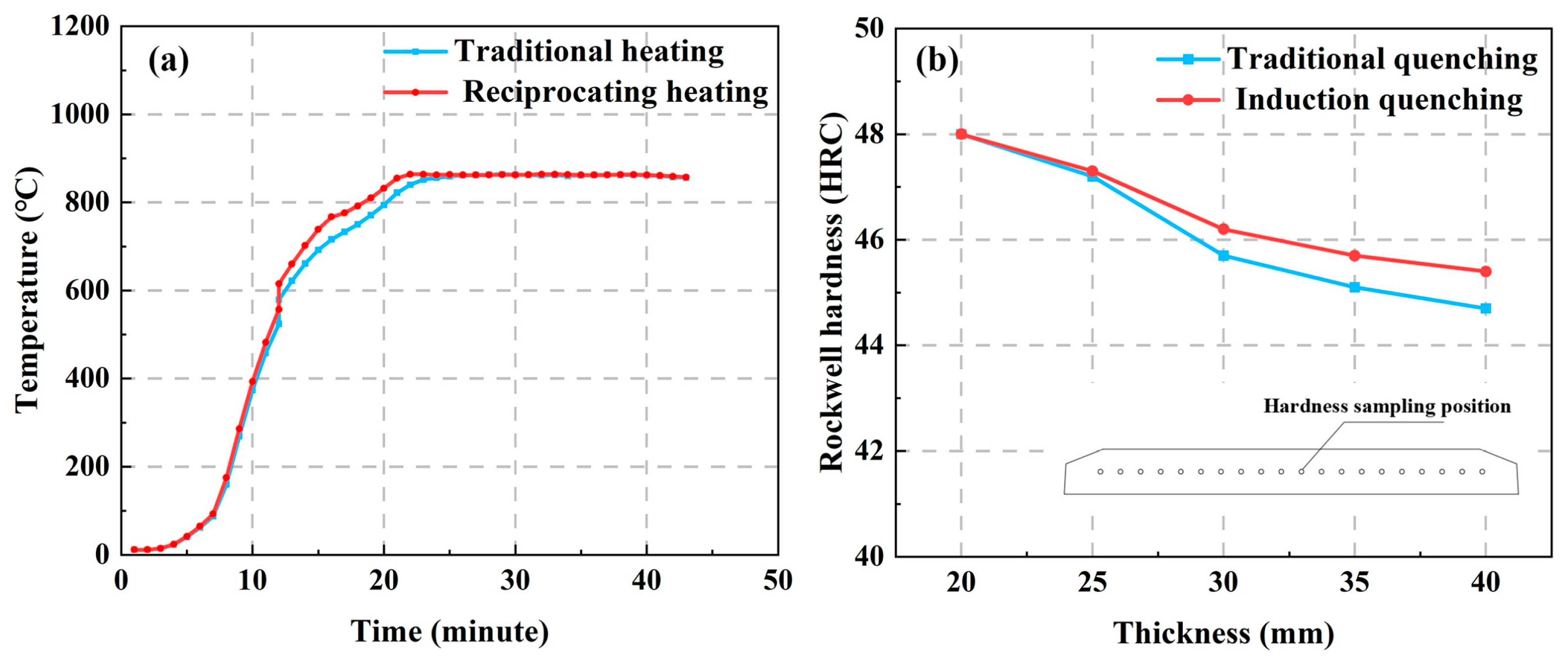
Figure 1. (a) Temperature detection in the core of the steel plates. (b) Relationship between core hardness and plate thickness after induction hardening.
Crystals 13 01210 g001
Figure 2. (a) Metallographic structure; (b) crystal boundary; (c) grain size distribution; (d) orientation angle distribution.
Crystals 13 01210 g002
Figure 3. HB400 IPF: (a) RD; (b) ND; (c) TD; (d) example of IPF diagram in each direction.
Crystals 13 01210 g003
Figure 4. Microstructures of HB400: (a) bright-field image (g3g mode) of dislocations with SAED; (b) bright-field image of polygonal phases with SAED and element distribution.
Crystals 13 01210 g004
Figure 5. The Brinell and Rockwell hardnesses of HB400.
Crystals 13 01210 g005
Figure 6. (a) Stress–strain curves of HB400 transverse longitudinal samples and fracture morphologies (a1,a2); (b) comparison with the same grade of steel (data from [6,19,20,21,22,23,24,25,26,27]).
Crystals 13 01210 g006
Figure 7. (a) Curves of friction coefficient with time for different loads in reciprocal mode and (b) average friction coefficient; (c) curves of friction coefficient with time for different loads in rotation mode and (d) average friction coefficient.
Crystals 13 01210 g007
Figure 8. (a) Wear trajectory profile under different loads in reciprocal mode. (b) Wear volume under different loads in reciprocal mode. (c) Wear trajectory profile under different loads in rotation mode. (d) Wear volume under different loads in rotation mode.
Crystals 13 01210 g008
Figure 9. Wear morphology of HB400 under different loads in reciprocal mode: (a) 100 N; (b) enlarged view of part of the area under 100 N load; (c) 200 N; (d) enlarged view of part of the area under 200 N load; (e) 300 N; (f) enlarged view of part of the area under 300 N load.
Crystals 13 01210 g009
Figure 10. Wear morphology of HB400 under different loads in rotation mode: (a) 100 N; (b) enlarged view of part of the area under 100 N load; (c) 200 N; (d) enlarged view of part of the area under 200 N load; (e) 300 N; (f) enlarged view of part of the area under 300 N load.
Crystals 13 01210 g010
Figure 11. (a) Wear rate of HB400 under different loads in reciprocal mode (data from [19,32,33]). (b) Wear rate of HB400 under different loads in rotation mode (data from [34,35]).
Crystals 13 01210 g011
Table 1. Chemical composition of the Hardox400 and HB400 (wt.%).
ElementFeCSiMnPSCrBCuMoNiTiAl
Hardox400Bal.0.180.71.60.020.011.00.004 0.250.25
HB400Bal.0.210.351.320.0170.0080.610.0020.022 0.0160.039
Table 2. Parameters of the frictional–wear experiment.
ModeLoad (N)Stroke/Diameter (mm)Frequency (Hz)/
Rate (r/min)
Time/s
Reciprocal100/200/3001011200
Rotation100/200/300102001200
Disclaimer/Publisher’s Note: The statements, opinions and data contained in all publications are solely those of the individual author(s) and contributor(s) and not of MDPI and/or the editor(s). MDPI and/or the editor(s) disclaim responsibility for any injury to people or property resulting from any ideas, methods, instructions or products referred to in the content.