Article

Study and Design of the Mitigation Structure of a Shell PBX Charge under Thermal Stimulation

1
State Key Laboratory of Explosion Science and Technology, Beijing Institute of Technology, Beijing 100081, China
2
The Eighth Military Representative Office of Air Force Equipment Ministry, Xi’an 710000, China
3
Naval Institute, Beijing 100161, China
4
Chongqing Hongyu Precision Industry Co., Ltd., Chongqing 402760, China
5
Xi’an Changfeng Research Institute of Mechanical-Electrical, Xi’an 710065, China
*
Author to whom correspondence should be addressed.
Crystals 2023, 13(6), 914; https://doi.org/10.3390/cryst13060914
Submission received: 5 May 2023 / Revised: 30 May 2023 / Accepted: 2 June 2023 / Published: 5 June 2023
(This article belongs to the Special Issue Advanced Energetic Materials: Testing and Modeling)

Abstract

:
To study the design method and pressure relief effect of the mitigation structure of a shell under the action of thermal stimulation, a systematic research method of theoretical calculation-simulation-experimental verification of the mitigation structure was established. Taking the shelled PBX charge as the test material, the pressure relief area that can effectively reduce the reaction intensity of the charge is obtained by theoretical calculation. The influence of the pressure relief hole area, distribution mode, and other factors on the pressure relief effect is calculated by simulation. The pressure relief effect of the mitigation structure was verified by the low-melting alloy plug with refined crystal structure for sealing the pressure relief hole and the cook-off test. The research results show that the critical pressure relief area is when the ratio of the area of the pressure relief hole to the surface area of the charge is AV/SB = 0.0189. When the number of openings increases to 6, the required pressure relief coefficient decreases to AV/SB = 0.0110; When the length/diameter ratio is greater than 5, the opening at one end cannot satisfy the reliable pressure relief of the shell. The designed low-melting-point alloy mitigation structure can form an effective pressure relief channel. With the increase in AV/SB from 0.0045 to 0.0180, the reaction intensity of the cook-off bomb is significantly reduced in both fast and slow cook-off, which improves the safety of the charge when subjected to unexpected thermal stimulation.

1. Introduction

During the process of production, transportation, storage, and usage, ammunition could be stimulated by unexpected sources, such as fire, which will lead to violent reactions and bring about major safety accidents. Accidental thermal stimulation is one of the most common accidental excitable sources encountered in the whole life cycle of ammunition. The charge ignites and burns under thermal stimulation. Huge personnel and economic losses would occur when the shell is sealed because the temperature and pressure will rise rapidly in the confined space of the charge, resulting in a chain reaction from combustion to deflation to detonation. Aiming at the thermal safety of ammunition, the improvement methods mainly include insensitive explosive and charging technology, shell pressure relief technology, thermal shock buffer technology, and other aspects [1]. The principle of shell pressure relief technology is that when ammunition is under a certain thermal stimulation condition, a pressure relief channel is formed through the mitigated structure on the shell to relieve the internal pressure of the ammunition, the self-heating reaction rate of the charge is suddenly reduced, so the severity of charge response is reduced. The decrease in the internal temperature, the decrease in the natural reaction rate, and the convection driven by the product bubbles collectively lead to a delay in the ignition time [2]; these factors reduce the reaction intensity of the charge, achieving the purpose of improving the safety performance of the assembly.
Research on the design of mitigation structures had already begun when the United States and European countries developed insensitive ammunition in the last century. After considerable technical accumulation, some mitigation structure design technologies have been successfully applied to model ammunition [3,4,5,6,7]. Therefore, the pressure relief technology of designing vent holes on the shell is an effective control method to improve the thermal safety of ammunition. William et al. [8] studied the response characteristics of explosives through a fast cook-off test and measured the internal pressure of ammunition through a pressure sensor. The results show that a vent hole can effectively reduce the response intensity of the ammunition under the condition of fast cooking. Glascoe et al. [9] conducted a slow cook-off test equipped with a pressure relief hole, compared a molten Composition-B explosive with an HMX-based agglomerated explosive, and found that the size of the molten cast explosive pressure relief hole was too small, which may improve the response intensity of the ammunition. The gas pressure inside the condensed explosive cannot be discharged in the form of bubbles, and the pressure relief hole has almost no effect. Kinney [10] calculated the critical area of the pressure relief channel according to the dynamic equilibrium relationship between the pressure increase rate when the charge facilitated the combustion reaction and the pressure decrease rate when the pressure relief channel was relieved. Hakan et al. [11] calculated the critical pressure relief area of the pressure relief channel according to the dynamic transport equilibrium relationship between the mass of the gas generated during the combustion of the charge and the mass of the gas discharged from the channel. Wardel et al. [12] set up two different venting methods to leak the gas inside the explosive from the top center and the top edge and found that the cook-off bomb with the vent set at the top center had a more severe response. Niu Gongjie [13] studied the influence of different distribution modes of pressure relief holes on the dose-response intensity and pointed out that the pressure relief hole should be set near the ignition position of the charge. Madsen et al. [14] studied the cook-off characteristics of four explosives, including molten Composition-B explosive, PAX-28, PBXN-109, and PBXN-9, under different vent hole sizes by scale testing and analyzed the selection of a low-melting-point material for plugging the pressure relief hole.
However, the abovementioned studies were only verified through theoretical calculations or experiments. The area of the pressure relief channel, the size of the pressure relief hole, or the feasibility of the low-melting-point material as a mitigation structure were not considered comprehensively, and the actual shell installation was not considered. It is difficult to provide a complete basis for the design of the mitigation structure of a shell without forming a systematic research method of the theoretical calculation-simulation-experimental verification of the mitigation structure.
Therefore, in this study, the pressure relief area and the distribution of pressure relief holes through the systematic design method of the mitigation structure was investigated, the appropriate filling material was selected, and the pressure relief effect under different pressure relief conditions and shell failure strength thresholds were analyzed by means of simulation and experimentation. Taking a polymer bonded explosive (PBX) charge as the research object, slow cook-off, and fast cook-off tests were used for verification, which can provide a reference for the design of insensitive munitions mitigation structures.

2. Shell Mitigation Structure Design

The key to the design of the mitigation structure is determining the area of the pressure relief channel, the arrangement of the pressure relief holes, and the selection of the filling material for the pressure relief holes. The material filling the pressure hole should not affect the use under normal working conditions so that it cannot only perform a sufficient role in exhaust and pressure relief but also meet the requirements of the structural strength of the shell.
Taking a standard cook-off bomb as an example, the shell mitigation structure was designed. The materials of the shell and end cover are #45 steel. The shell is 240 mm long, 60 mm in inner diameter, 66 mm in outer diameter, and 3 mm in thickness, and both ends of the body were machined with 45 mm external threads. The thickness of the end cover is 5 mm, the diameter is 73 mm, the internal thread is processed, the pitch is 1.5 mm, the charge is Φ60 mm × 240 mm, the length-diameter ratio is 4:1, the PBX pressed charge is filled, its content component is RDX/Al/Viton F2602 is 65.5/30/4.5, and the charge density is 1927 kg m−3. Among them, the RDX used is Class II, 0.075~0.300 mm. Al powder is 1–2 μm.

2.1. Pressure Relief Area Design

The pressure relief area of the mitigation structure needs to be designed according to different conditions to ensure the effect of the mitigation structure. The determination of the pressure relief area mainly considers the relationship between the pressure increase rate in the shell and the pressure release rate of the pressure relief passage. According to the research of Kinney [10], the pressure growth rate of the charge in the shell when burning is:
d p d t = R T B V d n d t = R T B V ρ M α ( A B T 0 ) S B P
where TB (°C) is the flame temperature when the charge burns; R is the universal gas constant, which is 8.314 J·mol−1·°C−1; V is the volume (m3); ρ is the density of the charge (kg m−3); M is the average molar mass of the gas molecules during combustion (kg mol−1); T0 is the temperature of the charge at ignition (°C); SB is the surface area of the charge (m2); P is the absolute charge pressure (bar); and α, A, and B are constants for the charge burning rate and temperature.
The pressure release rate of the pressure relief channel is calculated by the following formula:
d p d t = A V C D V a P
where AV is the area of the pressure relief hole (m2); CD is the exhaust coefficient, which is taken as 0.82 [15]; and a’ is the speed of the air passing through the air hole (m/s).
Combining Equations (1) and (2), when the pressure increase rate in the shell and the pressure release rate of the pressure relief channel are equal, the calculation formula of the critical area of the pressure relief channel can be obtained as:
A V S B = α ρ R T B M C D a A B T 0
Equation (3) shows that the ratio of the area of the exhaust passage to the combustion area of the charge can be directly obtained from the relevant physical and chemical parameters of the charge, and the critical pressure relief area can be determined.
The molar mass of the gaseous product of the elemental explosive RDX (C3H6N6O6) in the PBX charge is [16]:
M = 56 c + 88 d 8 b 2 c + 2 d + b = 27.2 g m o l
According to ref. [17] of the burning rate parameter:
1 r = A B T 0
In the formula, r is the burning speed of the charge. The other parameters were calibrated from previous studies [18] and experiments and the size of the pressure relief hole required for the ignition of PBX charges at different temperatures was calculated, as shown in Table 1.
Therefore, for a PBX charge with a charge size of Φ60 × 240 mm, the minimum AV/SB is 0.0189 when ignited at a temperature of 237 °C.

2.2. Design of the Pressure Relief Hole Distribution

At present, most of the pressure relief holes are designed to be distributed in the tail of the projectile, the wall of the projectile, etc. The distribution mode has an important influence on the charge reaction level, and the design of the pressure relief channel near the ignition position has a significant effect.
A numerical calculation model was established based on the cook-off experiment and the data in the literature [20], and the simulation model was a standard cook-off bomb of Φ60 × 240 mm. CFD fluent software was used to calculate the response position of the PBX charge at heating rates of 3.3 °C/h (0.055 °C/min), 0.1 °C/min, 0.5 °C/min, 1 °C/min, and 3.3 °C/min. The position distribution of the pressing holes provides the design basis. Figure 1 shows the position distribution of the ignition time. Figure 2 shows the changes in ignition position under different heating rates. When the charge material and the charge structure size are determined, the ignition position is mainly affected by the heating rate. With the acceleration of the heating rate, the reaction position first moved from the center of the charge to the two ends along the axis, then moved to the corner of the cylindrical section and the end cap.
Since the thermal decomposition temperature of the charge is constant when the charge reaches the decomposition temperature, the charge begins to decompose, and the released heat is transferred to the low-temperature charge and the outside of the shell. When the heating rate is low, there is more time for slow thermal decomposition to occur. At the same time, because the heat of charge decomposition is greater than the heat provided by the heating of the shell, the inward transfer of heat will lead to the decomposition of the internal charge. In contrast, the outward transfer is relatively smooth, and the temperature increase process in the shell is mainly caused by the heat of the charge decomposition control, resulting in the continuous movement of the reaction center to the charge center. When the temperature of the reaction center reaches the ignition temperature, ignition occurs, and the reaction center at this moment becomes the ignition position. When the heating rate is fast, ignition occurs before the high-temperature point is transferred to the center of the charge. The pressure relief channel is designed near the ignition position, which is conducive to the timely dissipation of the heat generated by the decomposition and reduces the temperature of the charge.
Therefore, for the PBX charge with a charge size of Φ60 × 240 mm, the pressure relief hole design can be considered at one or both ends close to the ignition position.

2.3. Design of Pressure Relief Hole Filling Material Design

Low-melting alloys are heat-sensitive, and their mechanical strength decreases at high temperatures. Under a certain ambient temperature and internal pressure, the mitigation structure of low-melting alloys are disabled and destroyed. These alloys can be used in the starting device of mitigation structures. Design requirements for mitigation structures of low-melting alloy plugs are as follows [21]:
(1)
These structures have sufficient strength under storage and transportation conditions and do not affect the normal use requirements of ammunition.
(2)
When the ammunition is subjected to unexpected thermal stimulation, such as high temperature, before reaching the lowest ignition point or explosion point of the ammunition, the mitigation structure must lose most of the strength, and the exhaust channel must be opened to reduce the reaction strength of the ammunition and improve the safety.
The slow cook-off response temperature of the PBX charge (RDX/Al/binder mass fraction of 65.5/30/4.5) used in this paper was obtained from the preliminary test of approximately 237 °C. Strickland et al. [22] pointed out that to effectively suppress the deflagration to detonation transition of energetic materials, the opening temperature of the pressure relief channel should be more than 60 °C lower than the slow cook-off response temperature; that is, the opening temperature of the pressure relief channel is approximately 177 °C. Therefore, the melting point of the low-melting-point alloy for the mitigation structures of the shell should be below the slow cook-off response temperature of the charge, and the mechanical strength of the low-melting alloy material is significantly reduced at a temperature of 177 °C. The structure is destroyed in this situation of internal pressure to open the pressure relief channel.
The melting point of the Sn-Zn binary alloy system is 198.5 °C, which meets the design requirements of mitigation structures. At the same time, the low-melting-point alloy must meet the requirements of temperature environment adaptability; that is, it must have good mechanical properties from −50~70 °C. Therefore, the Sn9Zn-3Al0.2La low-melting-point alloy with good mechanical properties was selected as the filling material of the pressure relief channel [23], and its mechanical properties are shown in Table 2. The addition of La element is to refine its crystal structure and improve its mechanical properties.

3. Analysis of Factors Affecting the Pressure Relief Effect

3.1. Simulation Model

The pressure relief process of the shell mitigation structure is a competitive process of unburned charge combustion and gas release, and different mitigation structures (such as the length/diameter ratio of the shell, the number of pressure relief holes, and the location) have a great influence on the pressure relief of confined spaces. The explosion process time of the charge is very short, the internal pressure changes greatly, and the explosion process is dangerous. The experimental research will be limited by the conditions of the site, testing methods, and safety. The simulation calculation can easily change the conditions, such as different mitigation structures, and a comprehensive analysis of the internal pressure of the shell can be conducted. The commonly used commercial software ANSYS Fluent was used to simulate the pressure relief process of the shelled charge under three-dimensional conditions. The purpose is to obtain the internal pressure changes in the shell during the pressure relief process in different sustained-release structural conditions and provide data information support for the design of mitigation structures.
The inlet mass source term can be defined as the product of the total reaction volume Aburn, the explosive burning velocity rburn, and the combustion product density ρburn in the shell [11]:
m ˙ inlet = A b u r n r b u r n ρ b u r n
The simple expression for the mass outflow after opening the pressure relief channel is:
m ˙ outlet = A v e n t u * ρ * C D
In the formula, CD is the exhaust coefficient, which is taken as 0.82 [15], and the other terms are solved by the following isentropic equations:
ρ * = P v e n t R T v e n t
u * = k R T v e n t M
P * = P c h a m b e r 1 + k 1 2 M 2 k k 1
T * = T c h a m b e r 1 + k 1 2 M 2 k k 1
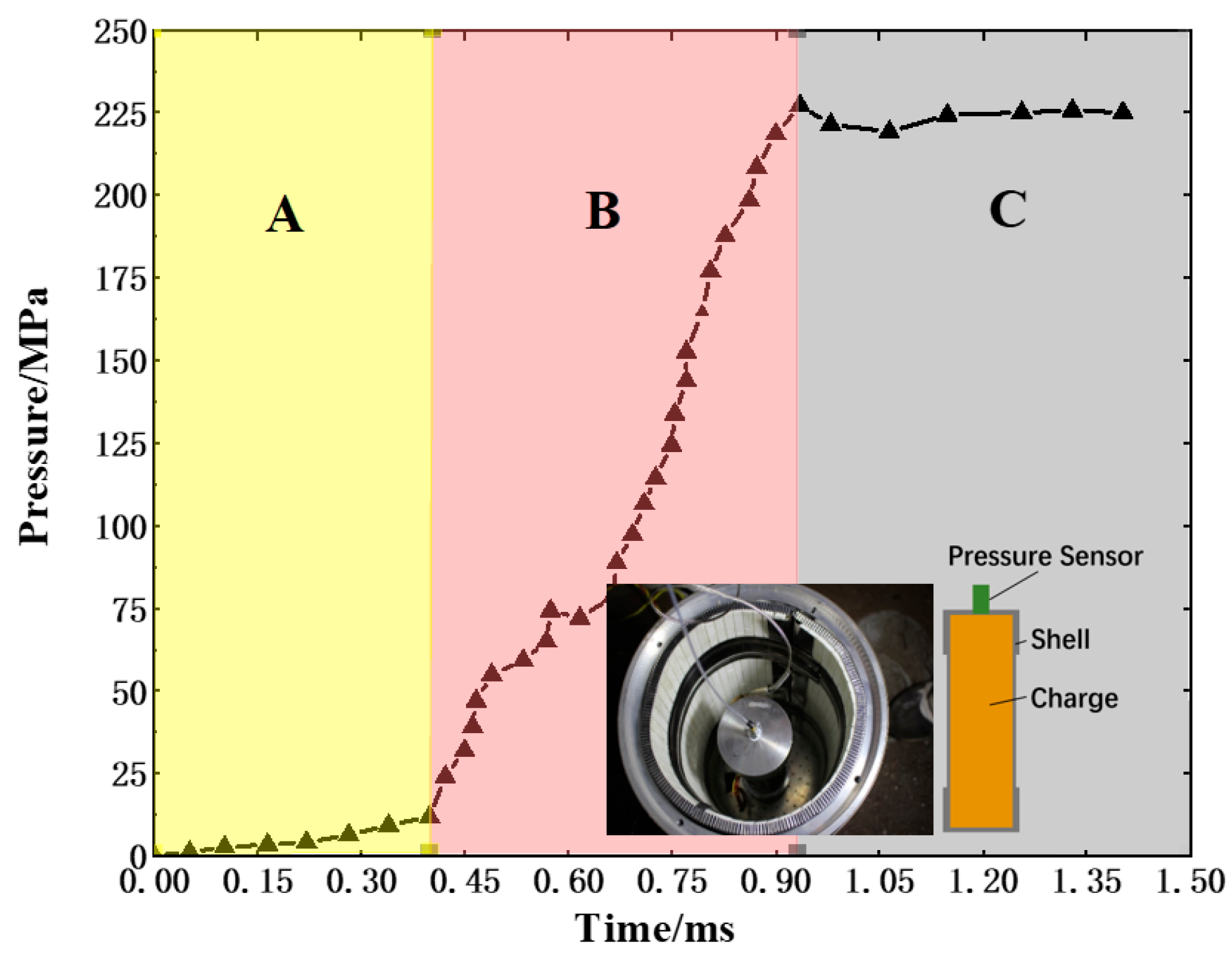
A schematic diagram of the description of the exhaust gas pressure relief process of the projectile is shown in Figure 3. The pressure-rising stage of the charge ignition stage is used as the input condition, and the UDF is loaded into the software to simulate the pressure-rising process. The pressure rise process caused by the combustion of the charge is calibrated with reference to the test results [24] (the pressure curve is shown in Figure 4). Test method: During the cook-off test, a piezoelectric pressure sensor is used to measure the pressure time-history curve inside the cook-off bombshell.

3.2. Simulation Results

3.2.1. Influence of the Number of Pressure Relief Holes

Figure 5 shows the variation in pressure with time when there is no mitigation structure and the critical dimension AV/SB = 0.0189. The different colored lines represent the pressure curves of different monitoring points, and the yellow stars represent the positions of the monitoring points. The curve with a sharp rise in pressure is the pressure curve designed without the mitigation structure, and monitoring points 1–7 are the critical pressure relief area pressure curve when the pressure relief channel is opened. The pressure rises when the charge starts to respond quickly is recorded as 0 times. It can be seen from the pressure curve without the mitigation structure that when the pressure relief channel is not opened, the pressure rises exponentially according to the set pressure rise rate. At 0.45 ms, the pressure reached 20.8 MPa, and finally exceeded the shell burst pressure and exploded. When the pressure relief channel is opened, when the breaking pressure of the low-melting-point alloy plug is 20.8 MPa, the pressures of monitoring points 1 and 2 near the pressure relief channel fluctuate rapidly, then fluctuate and rise and finally stabilize at 7.71 MPa and 17.08 MPa at 6 ms, respectively. Due to the pressure hysteresis effect, monitoring point 7 away from the pressure relief channel will first rise and reach a maximum value of 28.05 MPa at 1.07 ms, then oscillate and decrease. Then, the pressure in the shell is gradually decreased, then fluctuates. At approximately 4 ms, the pressure remains basically unchanged and stabilizes at 19.79 MPa. The pressure at other monitoring points has the same trend as monitoring point 7. The pressure first rises to a maximum value, then oscillates down due to the hysteresis effect over time, and the pressure at the last stable point is below 20 MPa, at this time, all areas in the shell exhibit equilibrium pressure relief. The timely opening of the pressure relief channel can effectively reduce the pressure in the shell, make the charge undergo a relatively stable combustion reaction, and reduce the probability of a more severe reaction. Since the pressure relief channel is a type of pressure opening, and the pressure at monitoring point 7, far from the pressure relief channel, is the innermost pressure point. If the equilibrium pressure of monitoring point 7 meets the design requirements, then other positions in the shell will also meet the design requirements. In the subsequent research and analysis of the pressure relief effect, only the pressure curve at monitoring point 7 away from the pressure relief channel was analyzed.
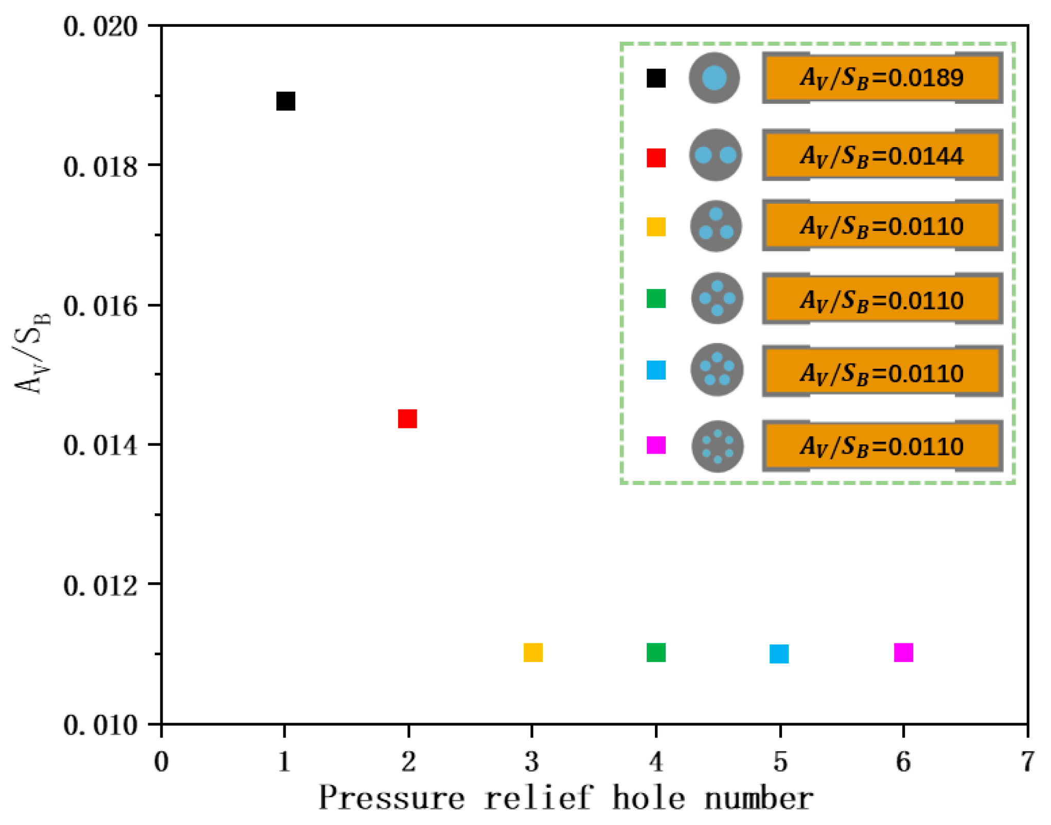
The influence of different numbers of relief holes (the number of relief holes is 1 to 6) on the pressure relief effect was studied, and the relief area at the same equilibrium pressure is shown in Figure 6. When the number of relief holes is 2, AV/SB = 0.0144 can achieve equilibrium pressure relief, and when the number of relief holes is 3~6, AV/SB is smaller, and only 0.0110 can achieve equilibrium pressure relief. This is because when the number of pressure relief holes increases, the air convection will be accelerated, the pressure will drop faster, and the degree of weakening of the shell will be reduced when the opening area is small. Therefore, the number of wells is 6, and AV/SB = 0.0110 is the control data.

3.2.2. Influence of Pressure Relief Area

Taking the number of openings as 6 and AV/SB = 0.0110 as the control, the influence of the area of the pressure relief holes (AV/SB are 0.0015, 0.0045, 0.0110, 0.0180, and 0.0268, respectively) on the pressure relief effect was investigated. The curve is shown in Figure 7. It can be seen that when the pressure relief channel is opened at 20.8 MPa, the pressure rise rate in the shell changes. However, because the monitoring point is located in the inner position, the pressure drop is delayed, so the pressure will continue to rise, and the pressure reaches a maximum value of 28 MPa at 1.06 ms. Then, according to the size of the pressure relief area, the subsequent pressure will oscillate down or up. When the aperture is 11 mm, the equilibrium pressure is maintained at 19.74 MPa at approximately 4 ms. It can be seen that the area of the pressure relief channel at this time is the equilibrium pressure threshold in this condition. When the apertures are 14 mm and 17 mm, the area is in an equilibrium pressure relief state, and the equilibrium pressures at 6 ms are 18.24 MPa and 17.00 MPa, respectively. When the aperture is 4 mm and 7 mm, disequilibrium pressure relief occurs at this time, and the pressures at 6 ms are 36.93 MPa and 22.72 MPa, respectively. Then, the pressure inside the shell will continue to rise, eventually reaching the burst pressure of the shell. It can be seen that the timely opening of the pressure relief channel can effectively reduce the pressure in the shell, and with the reduction in the pressure relief area, the pressure in the shell will change from equilibrium pressure relief to disequilibrium pressure relief.

3.2.3. Influence of the Length/Diameter Ratio

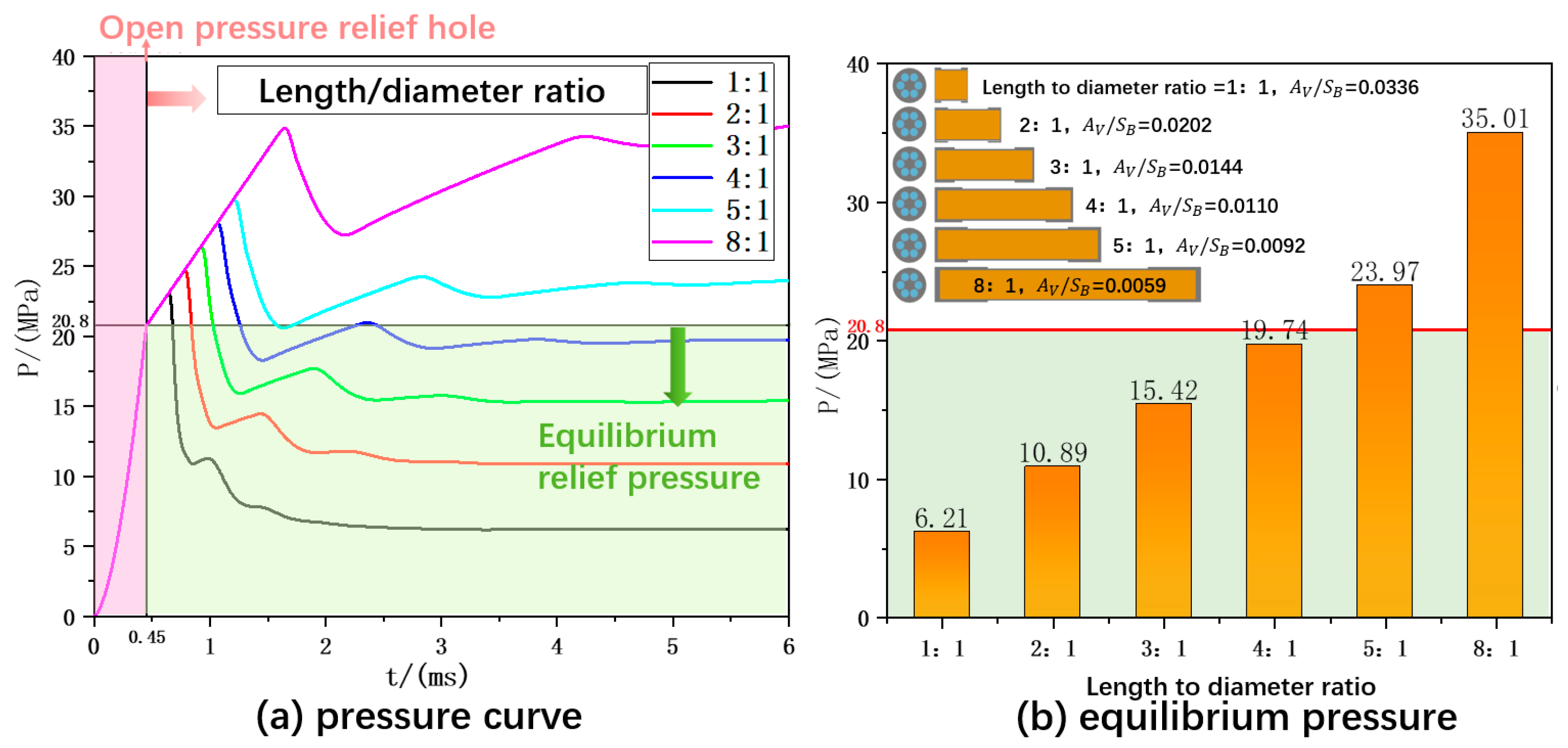
The pressure curves in different length/diameter ratios (we kept the hole size unchanged at this time, and the hole size under different length/diameter ratios was 11 mm) are shown in Figure 8. It can be seen that with an increasing length/diameter ratio, the pressure hysteresis effect is more serious after the pressure relief channel is opened. When the length/diameter ratio is 4, the equilibrium pressure relief state will finally be formed, and the pressure is 19.74 MPa at 6 ms. When the length/diameter ratio is less than 4, the equilibrium pressure relief is satisfied, and the pressure is all less than 20.8 Mpa. As the length/diameter ratio decreases, the pressure in the shell at equilibrium is also smaller. When the length/diameter ratio is 5 and 8, the pressure first oscillates and drops to a certain value, then continues to rise while the pressure relief channel is opened. The rising rate is related to the length/diameter ratio. The larger the length/diameter ratio, the faster the rising rate. At 6 ms, the pressure in the shell is 23.97 MPa and 35.01 MPa, which cannot provide a good pressure relief effect, resulting in unequal pressure relief. When the length/diameter ratio is 4, it is the pressure relief threshold in this condition, and when the length/diameter ratio is greater than 4, equilibrium pressure relief cannot be formed.
The equilibrium pressure in different length/diameter ratios was studied, the AV/SB required to achieve equilibrium pressure relief in different length/diameter ratios was calculated, and the results are shown in Figure 9. It can be seen that with an increasing length/diameter ratio, a larger pressure relief area is needed, and the increase is approximately exponential. When the length/diameter ratio is 5, the pressure relief area has reached the maximum critical area at this time (one end can no longer open a larger aperture). When the aspect ratio is 8, the equilibrium pressure relief cannot be performed in the condition that one end is fully open, indicating that the opening of one end cannot meet the pressure relief conditions at this time, and it needs to be considered in combination with other mitigation structure designs.

3.2.4. Influence of the Pressure Relief Hole Location

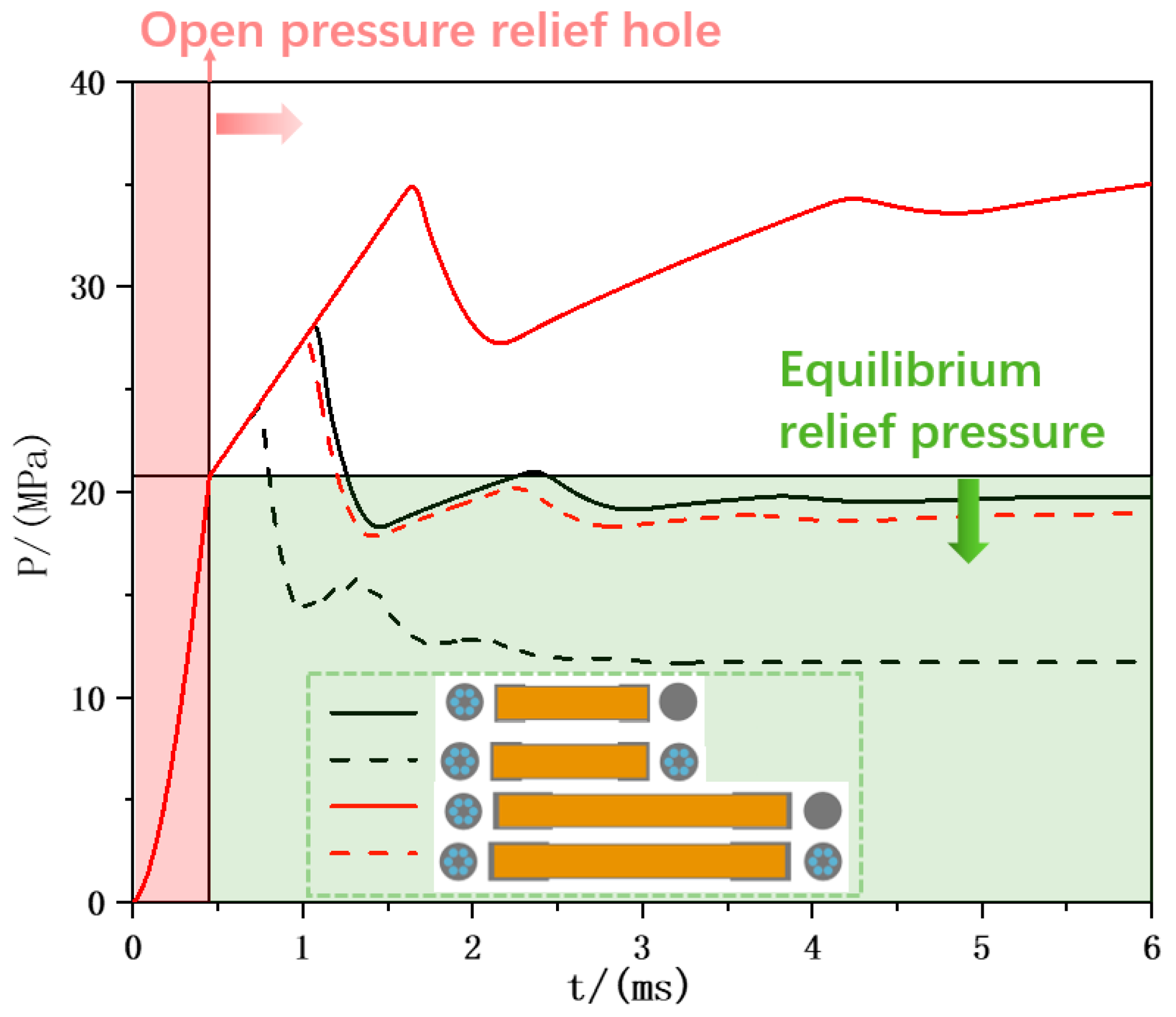
Taking the hole diameter as 11 mm and comparing the influence of the position of the pressure relief hole on the pressure relief effect in different length/diameter ratios, the pressure curve is shown in Figure 10. When the length/diameter ratio is 4, an equilibrium pressure relief will be formed, and at 6 ms, the equilibrium pressure of the openings at both ends is 11.71 MPa, which is lower than the equilibrium pressure of the openings at one end of 19.74 MPa. When the ratio is 8, one end of the hole cannot meet the pressure relief requirements, but when the two ends are opened, the pressure is 18.95 MPa at 6 ms, which meets the equilibrium pressure relief requirements. When the length/diameter ratio is too large, the pressure relief method can be adopted at both ends to relieve pressure. The reason for the analysis is that when the holes are opened at both ends, the pressure at the central position can be released from both ends at the same time, which actually reduces the length/diameter ratio of the shell. Therefore, the pressure relief effect of the holes at both ends is better than that of the holes at one end. Therefore, when the holes are opened at both ends, the disequilibrium pressure relief can be transformed into an equilibrium pressure relief in certain conditions, and the pressure originally in the equilibrium pressure relief state can be lower so that the pressure can be released faster and more effectively.

4. Test of Pressure Relief Hole Plugging Structure Strength

4.1. Hydrostatic Pressure in the High-Temperature Test

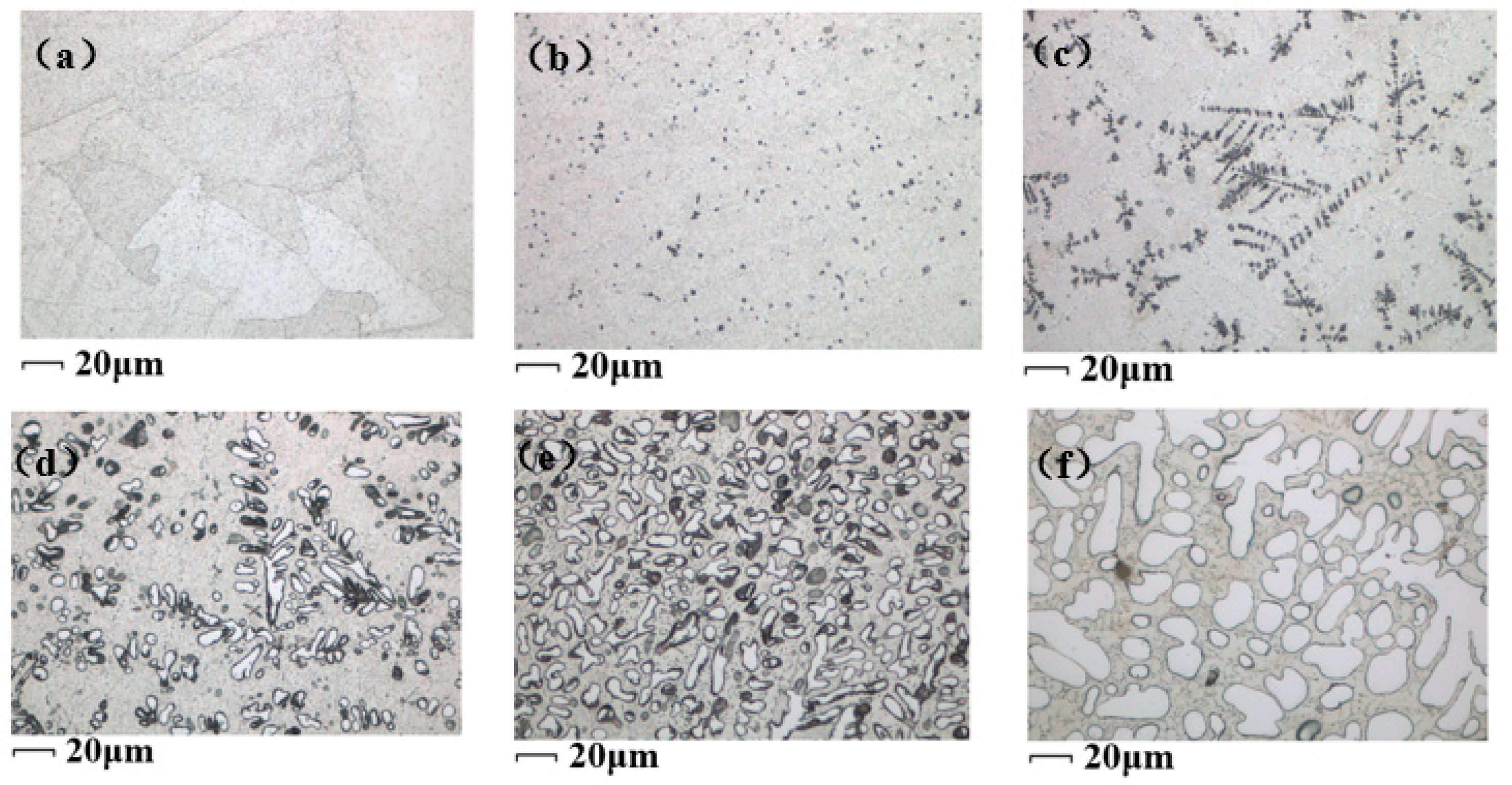
Figure 11 shows the metallographic structure of six Sn-Zn-Al La alloys with different Al contents. It is found that as the Al content increases, the gray matrix is an Sn-Zn eutectic phase, while the dotted black is a rich Zn phase. With the addition of Al, the microstructure becomes coarser and coarser. Black dendritic tissue gradually increases and the microstructure distribution of each alloy phase in the eutectic alloy Sn9Zn is relatively uniform. As the Al content continues to increase, needle-like or dendritic Al phases gradually appear at grain boundaries or interdendritic boundaries. When the Al content increases to 10%, the black dendritic structure gradually decreases, and increasingly circular silver phases are formed in the alloy phase. The finer the crystal, the stronger the mechanical properties. Therefore, we chose Sn9Zn-3Al0.2La for the design of the sustained-release structure.
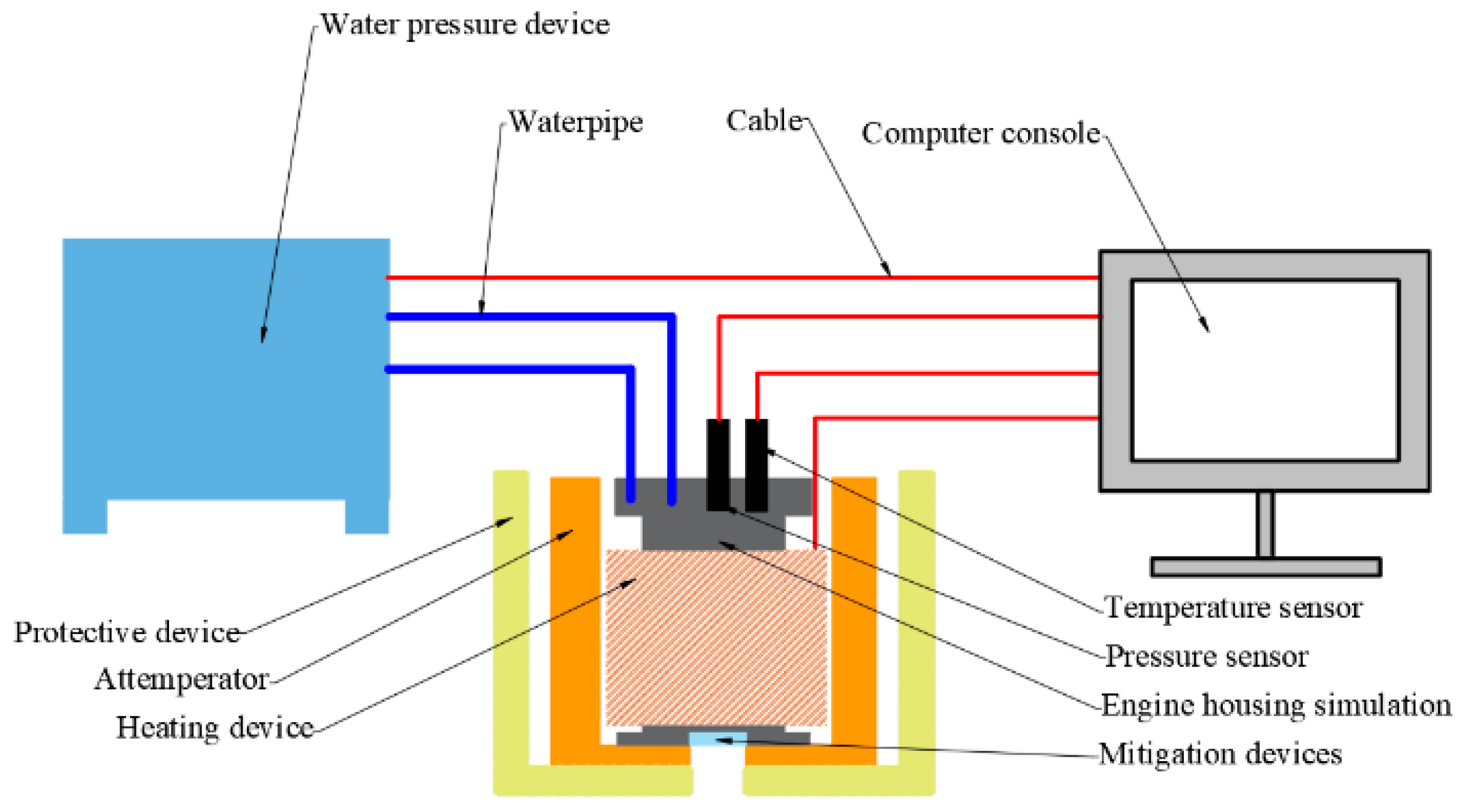
According to the self-developed hydrostatic pressure of the high-temperature test system [25], a comparative experiment was carried out to test the actual pressure-bearing capacity and pressure relief effect of low-melting-point alloys in a set high-temperature environment. The hydrostatic pressure in the high-temperature test system is shown in Figure 12. Three experiments were carried out, namely, the high-temperature blasting pressure of the shell without a mitigation structure and the normal-temperature/high-temperature blasting pressure of the Sn9Zn-3Al0.2La mitigation structure. The test methods are shown in Table 3.

4.2. Results of the Low-Melting-Point Alloy Plug Strength Test

The pressure time-history curve of the hydraulic experiment of the shell-simulated sample is shown in Figure 13. It can be seen from the comparison that the mitigation structure has a complete structure at normal temperature. In the temperature environment of 175 °C, through the design of the pressure relief diaphragm mitigation structure, the restraint strength of the simulation shell at 175 °C is reduced by nearly 50%, from 40 MPa to 21.21 MPa, which basically meets the start-up requirements of the pressure relief channel. It can be seen from the photos of the wreckage of the pressure relief diaphragm after the experiment that the mitigation structure loses most of its strength under the action of high temperature, fails under the action of internal pressure, and forms a pressure relief channel, which can be applied to the design of the mitigation structure of the shell. This experiment verifies that the low-melting-point alloy mitigation structure can open the pressure relief exhaust channel in advance under the action of a particular temperature environment and internal pressure, which meets the design requirements of the low-melting-point alloy plug mitigation structure.

5. Mitigation Design and Cook-Off Test of the Cook-Off Bomb

To verify the pressure relief effect of the designed mitigation structure, a standard cook-off bomb was designed and sealed with low-melting-point alloy plugs. The test site was arranged to conduct fast cook-off and slow cook-off tests to study the mitigation effect of insensitive munitions for reference.

5.1. Design of the Mitigation Structure of the Shelled PBX Charge

A schematic diagram of the structure of the cook-off bomb is shown in Figure 14. Its structure is mainly composed of a shell, front and rear covers, a charge column, and a low-melting-point alloy plug. Six circular holes were opened along the periphery of one end face, and four pressure relief areas were chosen for the circular holes (without the mitigation structure, AV/SB were 0.0045, 0.0110, and 0.0180, respectively). The mitigation structure design of the shell was carried out under preset working conditions. The low melting point alloy material used to seal the pressure relief channel must meet the structural strength requirements. Therefore, the pressure relief mitigation structure adopted a threaded mechanical connection. The material of the low-melting-point alloy plug is Sn9Zn-3Al0.2La, which was processed according to the size of different pressure relief channels.

5.2. Test Conditions

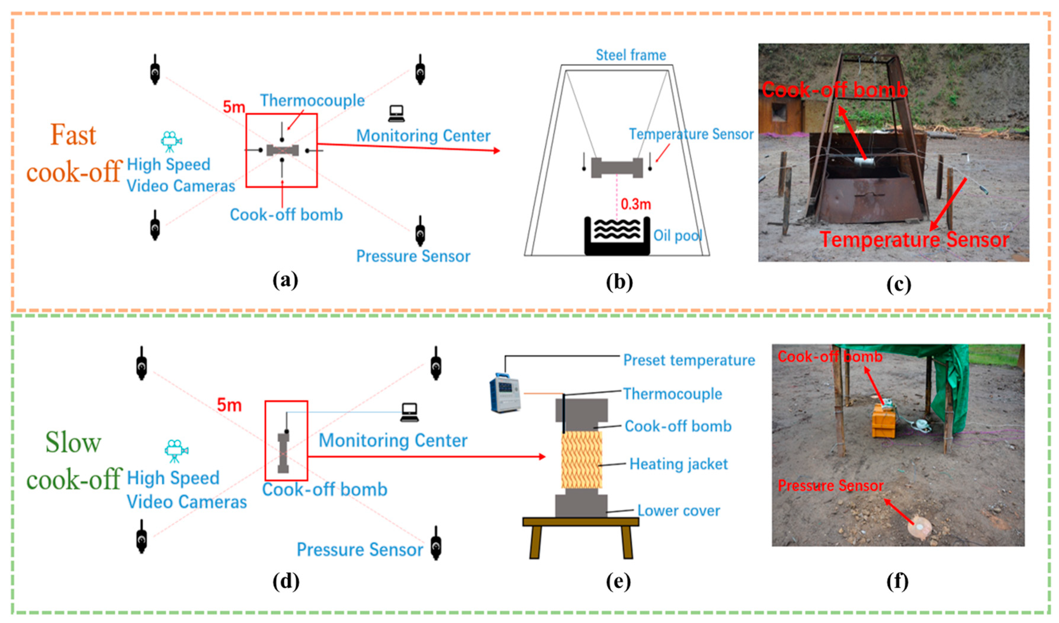
The layout of the test site is shown in Figure 15, and the design test is shown in Table 4. In the slow cook-off test, the bomb was heated by remote control, and the temperature rose at the rate of 1 °C/min until the cook-off bomb experienced combustion and an explosion reaction or the temperature reached 400 °C and no reaction occurred. After the test was completed, the cook-off bomb was destroyed. The prepared cook-off bomb was hung horizontally on the support frame. The center was 300 mm directly above the combustion source. Aviation kerosene and an appropriate amount of gasoline were injected into the oil tank to the specified scale line, and the electric ignition device was placed into the base and energized. At the same time, a ground field overpressure sensor was placed 5 m before and after the cook-off bomb. Place the Revealer High-Speed Camera X113, the maximum shooting rate is 25,000 FPS, the maximum memory is 64 GB, the full resolution is 1280 × 1024, and the minimum exposure time is 1 μs, as shown in Figure 16. The response characteristics of the bomb under the state of cook-off were evaluated by the state of the cook-off bomb after the test, the deformation of the shell, and other effective verification methods. Refer to the US military standard MIL-STD-2105D “Nonnuclear ammunitions of risk assessment” [26] to determine the response level.

5.3. Results and Analysis

5.3.1. Slow Cook-Off Test

To study the pressure relief effects of the mitigation structure in the condition of slow cook-off, the cook-off bomb S-1 without mitigation structure and the cook-off bomb S-2 with AV/SB = 1.10% and the mitigation structure were tested. Relevant experiments were carried out, and the reaction characteristics and the effectiveness of the mitigation structure were studied.
During the test, a large amount of gas was first observed in the mitigation structure cook-off bomb, as shown in Figure 17. It can be seen that the exhaust effect of the mitigation structure is obviously. Due to the burning rate of the charge in the later stage is too fast, a thrust is formed, which makes the cook-off bomb break away from the shackles of the heating belt, which stops the heating environment, as shown in Figure 17d. The charge was kept away from the fire environment, and it failed to react completely. The residual charge is shown in Figure 17e. It was further confirmed that the mitigation structure could open well and form a pressure relief channel.
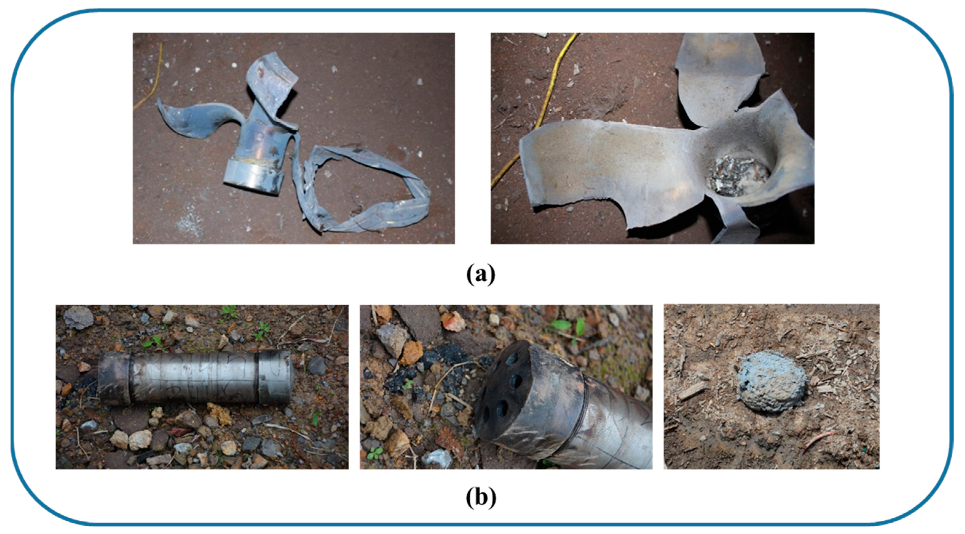
The slow cook-off results of the cook-off bomb are shown in Table 5, and the shell fragments are shown in Figure 18. The end cover at one end of the shell was punched open after the reaction of the S-1 cook-off bomb, and the end cover at the other end was still connected to the shell. The side wall of the shell was severely torn and broken into several large fragments, there was almost no residual explosive inside, no shock wave overpressure was detected in the test, and the reaction level was deflagration. When the temperature of the S-2 cook-off bomb is approximately 193 °C, the shell end cap screws are punched out. During the initial reaction of the charge, the gas generated by thermal decomposition forms a thrust, which keeps the bomb shell away from the fire environment but does not react completely. The end caps at both ends of the shell are slightly deflected, but the shell is intact and not damaged, and there is residual explosive inside that has not reacted completely. No shock wave overpressure is detected, and the reaction level is combustion and below. Therefore, it can be seen that the mitigation structure can effectively reduce the internal pressure of the shell during the reaction of the charge, keep the shell away from the fire environment, effectively reducing the intensity of the thermal reaction of the PBX charge, and improve the safety of the slow cook-off of the charge

5.3.2. Fast Cook-Off Test

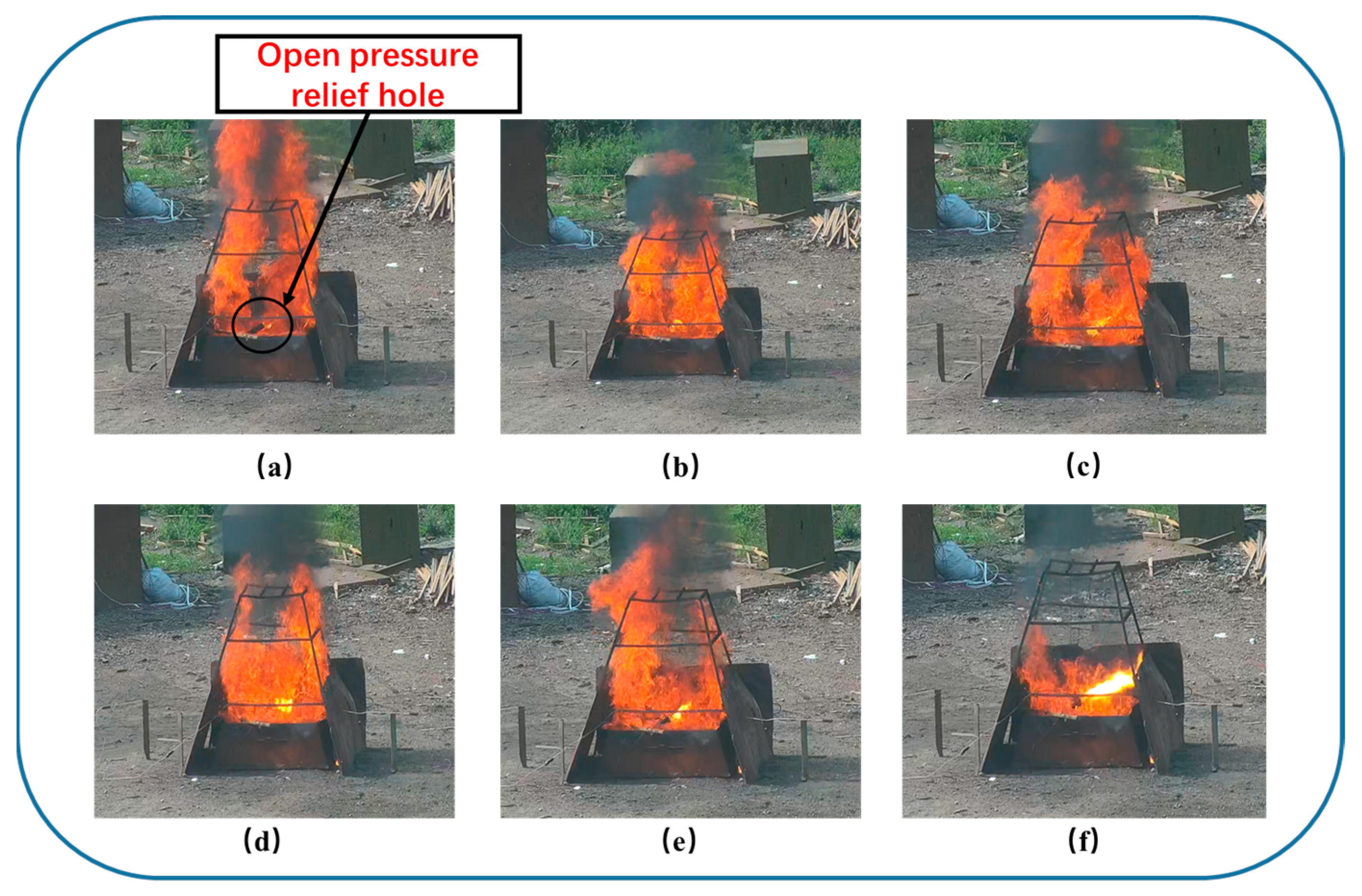
To study the pressure relief reaction of the mitigation structure in the condition of fast cook-off, relevant experiments were carried out on three kinds of mitigation structure cook-off bombs with pressure relief areas (AV/SB are 0.45% (F-1), 1.10% (F-2) and 1.80% (F-3)), and the reaction characteristics and the pressure relief effect of the mitigation structure were studied. During the test, a large amount of gas can be observed from the mitigation structure cook-off bomb, as shown in Figure 19. For the cook-off bomb with the mitigation structure, there is a clear gas flow discharged from the pressure relief channel before the reaction, which confirms that the pressure relief channel can perform a good role in pressure relief.
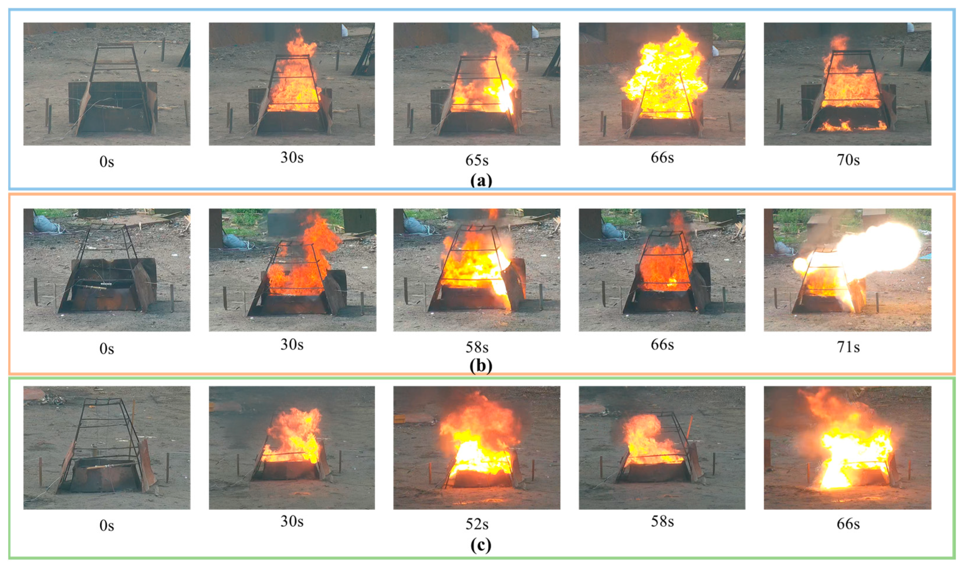
Video screenshots of each cook-off bomb at different times are shown in Figure 20. It can be seen that it experienced two explosions at 58 s and 71 s, respectively, while F-3 experienced two explosions at 52 s and 66 s, respectively. This is because the response of the cook-off bomb is divided into two stages. In the first stage, after the internal pressure of the charge reaches the pressure threshold of the alloy plug, the alloy plug is destroyed, the gas product breaks through the mitigation structure, the pressure relief channel is opened, and a large-scale fireball is formed, which lasts for approximately 13~14 s. In the second stage, the area of the pressure relief channel formed by the mitigation structure is small, and the pressure release rate of the pressure relief channel is less than the increased rate of the pressure in the shell, resulting in a secondary explosion. The upper-end cover is slightly deformed to create a deflection until the charge in the shell is completely burned. The F-1 cook-off bomb only exploded once at 65 s because the pressure relief area is small, so the pressure release rate is much smaller than the pressure growth rate in the shell, which causes direct damage to the shell, as shown in Figure 20a at 70 s. The shell fragments impacted and destroyed the oil sump. Therefore, when AV/SB is more than 1.10%, it can be clearly observed that the pressure relief channel is open, while when AV/SB is 0.45%, the pressure relief area is small, and the pressure relief cannot be fully discharged.
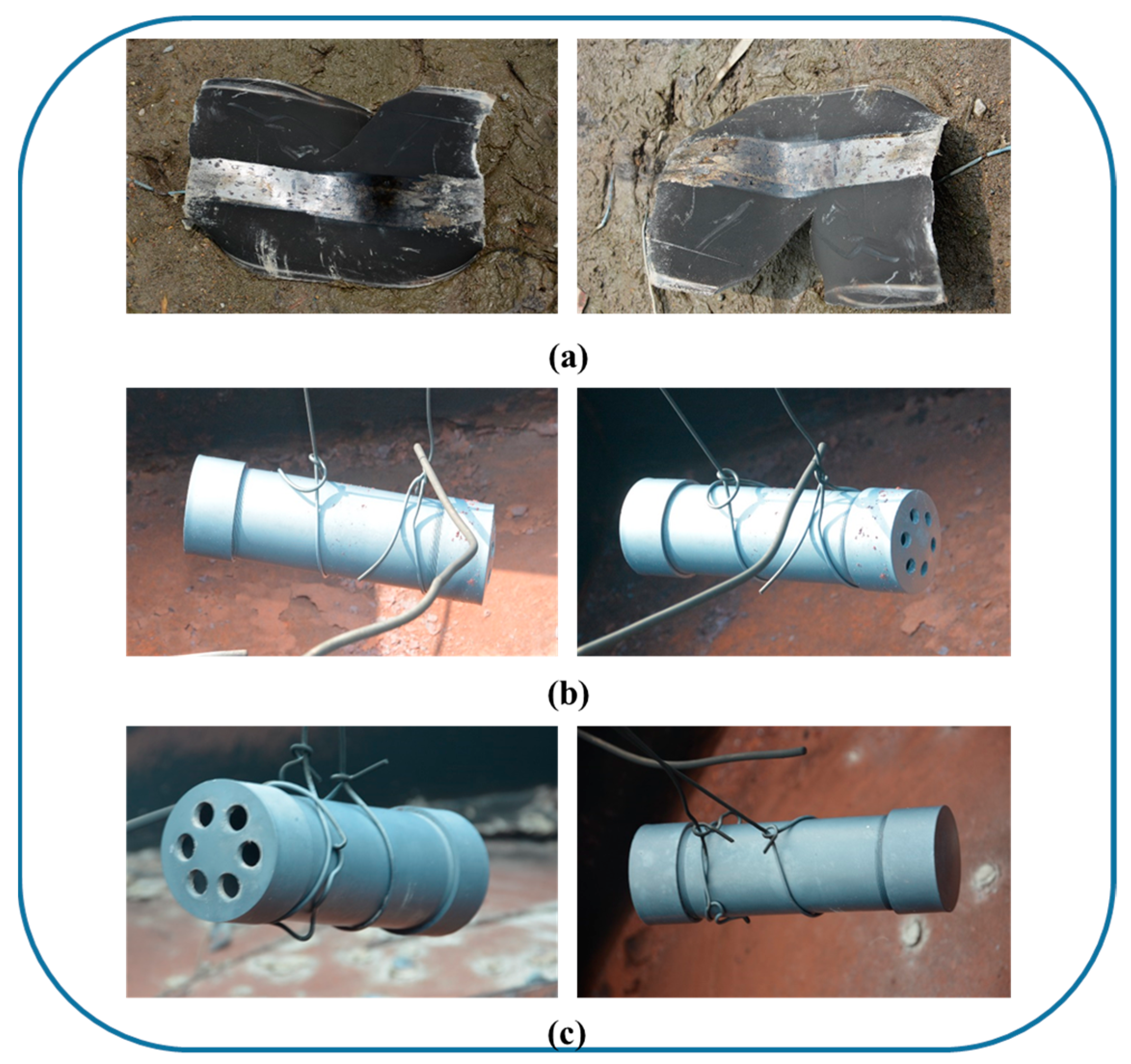
The fast cook-off results of the cook-off bomb are shown in Table 6, and the shell fragments are shown in Figure 21. The difference in the reaction time of different mitigation structures is very small, and the reaction levels are also combustion, but the intensity of combustion is different. The shell of the F-1 cook-off bomb is punched open, the two end caps are washed away, the shell is torn and deformed, and the reaction level is deflagration. The end cap screws of the F-2 cook-off bomb are punched out, the shell is completely without tearing occurs, the end caps at both ends are deformed, and the reaction level is combustion. The end cap screws of the F-3 cook-off bomb are punched open, the shell is intact, and no tearing occurs. The end cap at the end with the pressure relief channel is slightly deformed, and the reaction level is burning. Deflagration and the following reactions all occur for cook-off bombs with mitigation structures. When the pressure relief area increases, although the combustion reaction occurs, the severity of the reaction gradually decreases from the rupture of the product on site and the video. This shows that the increase in the pressure relief area has a certain effect on reducing the reaction level of the ammunition, which can improve the thermal safety of the ammunition.
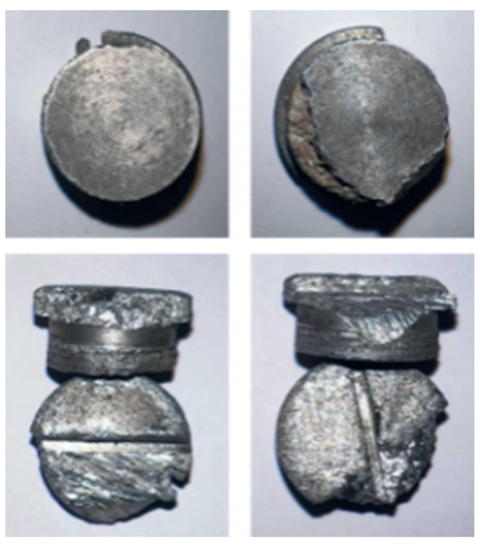
Figure 22 shows the wreckages of the low-melting-point alloy plug with a diameter of 14 mm in the F-3 cook-off bomb after the test. The alloy plugs of the F-1 and F-2 cook-off bombs were not found. The overall structure of the alloy plug is basically intact. The reason why the screw is ejected is because the high temperature softens the alloy plug and reduces the mechanical strength. During the action of the internal pressure of the shell, the thread fails and is damaged, and the pressure relief channel is opened to achieve effective pressure relief inside the shell. The damage to the screw cap is caused by spraying out during the first explosion and hitting the witness board or other objects, and experiencing damage. In summary, the above phenomena show that the designed mitigation structure can reliably relieve pressure during the cook-off process and improve the thermal safety of the charge.

6. Conclusions

In this paper, the design method of the mitigation structure is established, the influence of different mitigation structure designs on the pressure relief effect is simulated and calculated, and the mitigation structure is designed and verified by the cook-off experiment. The study found:
(1)
For PBX explosives, when the length/diameter ratio is 4 and AV/SB = 0.0189, the reaction intensity can be effectively reduced.
(2)
As the number of relief holes increases, the required relief area will decrease. When the number of relief holes is 6, AV/SB = 0.0110 is the equilibrium pressure relief size.
(3)
When AV/SB ≤ 0.011, the balanced pressure relief of the shell pressure relief process can be effectively realized, and as the pressure relief area of the mitigation structure is larger, the reaction intensity is smaller.
The work of this paper provides a reference research method for the design of the mitigation structure of a shelled charge under the action of thermal stimulation and the mitigation structure of the shell.

Author Contributions

Conceptualization, J.N. and R.L.; methodology and formal analysis, J.L.; investigation, J.L. and M.H.; resources, G.J.; data curation, X.S.; writing—original draft preparation, J.L.; writing—review and editing, J.N.; supervision, X.W. and B.H.; funding acquisition, J.N. All authors have read and agreed to the published version of the manuscript.

Funding

This work was supported by the National Natural Science Foundation of China [grant numbers 11772058] (Jianxin Nie).

Institutional Review Board Statement

Not applicable.

Data Availability Statement

The raw/processed data required to reproduce these findings cannot be shared at this time as the data also forms part of an ongoing study.

Conflicts of Interest

The authors declare no conflict of interest.

References

  1. Powell, I.J. Insensitive Munitions—Design Principles and Technology Developments. Propellants Explos. Pyrotech. 2016, 41, 409–413. [Google Scholar] [CrossRef]
  2. Wang, Q.; Zhi, X.; Xiao, Y. Analysis of the effect of a venting structure on slow cookoff of Comp-B based on a universal cookoff mode. Explos. Shock Waves 2022, 42, 61–69. [Google Scholar] [CrossRef]
  3. Robert, H.; Zachary, A. Spears Matthew Sanford. Advanced Precision Kill Weapon System (APKWS) IM Solutions. In Proceedings of the Insensitive Munitions & Energetic Materials Technology Symposium (2006), Bristol, UK, 24–28 April 2006. [Google Scholar]
  4. Stephen, K.; Fred, B. Joint General Purpose Bomb Insensitive Munitions Program. In Proceedings of the Insensitive Munitions & Energetic Materials Technology Symposium (2006), Bristol, UK, 24–28 April 2006. [Google Scholar]
  5. Tony, W. General Purpose Bomb Fast Cook-off Mitigation Techniques. In Proceedings of the Insensitive Munitions & Energetic Materials Technology Symposium (2010), Munich, Germany, 11–14 October 2010. [Google Scholar]
  6. Stephen, K. Venting Techniques for Penetrator Warheads. In Proceedings of the Insensitive Munitions & Energetic Materials Technology Symposium (2010), Munich, Germany, 11–14 October 2010. [Google Scholar]
  7. Stephen, K. Success in Venting Penetrator Warheads. In Proceedings of the Insensitive Munitions & Energetic Materials Technology Symposium (2012), Las Vegas, NV, USA, 14–17 May 2012. [Google Scholar]
  8. William, C.; Enic, E.; Adcl, S. Fast Cook-off Tests Report; Center for the Simulation of Accidental Fires & Explosions: Salt Lake City, UT, USA, 2003. [Google Scholar]
  9. Glascoe, E.; Dehaven, M.; McClelland, M.; Greenwood, D.; Springer, H.; Maienschein, J. Mechanisms of Comp-B Thermal Explosions. In Proceedings of the 15th International Detonation Symposium (2014), San Francisco, CA, USA, 13–18 July 2014. [Google Scholar]
  10. Kinney, G.; Sewell, R. Venting of Explosions; NWC TM 2448; Naval Weapons Center: China Lake, CA, USA, 1974. [Google Scholar]
  11. Sahin, H.; Narin, B.; Kurtulus, F.D. Development of a design methodology against fast cook-off threat for insensitive munitions. Propellants Explos. Pyrotech. 2016, 41, 580–587. [Google Scholar] [CrossRef]
  12. Wardell, J.; Maienschein, J. The Scaled Thermal Explosion Experiment. In Proceedings of the 12th International Detonation Symposium (2002), San Diego, CA, USA, 11–16 August 2002. [Google Scholar]
  13. Niu, G. Experimental study on the fast cook-off of ammunition with pressure mitigation structure at head. In Proceedings of the Symposium on Energetic Materials and Insensitive Munitions (2016), Nashville, TN, USA, 12–15 September 2016. [Google Scholar]
  14. Madsen, T.; Fisher, S.; Baker, E.; Suarez, D.; Fuchs, B. Explosive Venting Technology for Cook-off Response Mitigation; Technical Report ARMET-TR-10003; Army Armament Research Development and Engineering Center Picatinny Arsenal nj Energetics Warheads and Manufacturing Technology Directorate: Picatinny Arsenal, NJ, USA, 2010. [Google Scholar]
  15. Mcchristian, L.; Cistano, J.; Foxx, C.; Hartmann, W.; Murphy, W.; Stauner, R.; Takata, A. Vulnerability of Nuclear Weapon Systems to Fire Studies of Burning Explosives; Report RTD-TDR-63-3086; IIT Research Institute: Chicago, IL, USA, 1963. [Google Scholar]
  16. Hu, R.; Zhao, F.; Gao, H.; Yao, E. Estimation of detonation performances of explosives using M, ρ, ∆fH, Cp, Tig or b of C-H-O-N explosives and ∆fH of detonation products. Chin. J. Explos. Propellants 2013, 36, 20–23. [Google Scholar] [CrossRef]
  17. Graham, J. Mitigation of Fuel Fire Threat to Large Rocket Motors by Venting. In Proceedings of the 2010 Insensitive Munitions & Energetic Materials Technology Symposium (2010), Munich, Germany, 11–14 October 2010. [Google Scholar]
  18. Sinditskii, V.; Levshenkov, I.; Egorshev, Y.; Serushkin, V. Study on Combustion and Thermal Decomposition of 1,1-Diamino-2,2-dinitroethylene (FOX-7). In Proceedings of the Inter Seminar Europyro & Inter Pyrotechnics Seminar, Saint-Malo (2003), Saint-Malo, France, 23–27 June 2003. [Google Scholar]
  19. Chen, K.; Huang, H.; Lu, Z.; Nie, S.; Jiang, Z. Experimental Study on Cook-Off Test for Melt-Cast and Cast-Cured Explosive at Strong Constraint. J. Sichuan Ordnance 2015, 36, 133–136. [Google Scholar] [CrossRef]
  20. Kou, Y.; Chen, L.; Ma, X.; Zhao, P.; Lu, J.; Wu, J. Cook-off experimental and numerical simulation of RDX-based aluminized explosives. Acta Armamentarii 2019, 40, 978–989. [Google Scholar] [CrossRef]
  21. Fisher, M. Shape Memory Polymer (SMP) Venting Mechanism for Munitions. In Proceedings of the NDIA/MSIAC Insensitive Munitions & Energetic Materials Technology Symposium (2010), Munich, Germany, 11–14 October 2010. [Google Scholar]
  22. Strickland, A. Development of IM Brimstone rocket motor; An IM, minimum smoke, air-launched system. In Proceedings of the 2015 Insensitive Munitions & Energetic Materials Technology Symposium (2015), Rome, Italy, 18–21 May 2015. [Google Scholar]
  23. Wei, T.; Li, N.; Nie, J.; Liang, J.; Guo, Z.; Yan, S.; Zhang, T.; Jiao, Q. The properties of Sn–Zn–Al–La fusible alloy for mitigation devices of solid propellant rocket motors. Def. Technol. 2022, 18, 1688–1696. [Google Scholar] [CrossRef]
  24. Nie, J.; Li, X.; Guo, X.; Zhang, H.; Yan, S.; Zhang, T. Study on Response Characteristics of Insensitive PBX Explosive in Shell under Slow Cook-off. J. Saf. Environ. 2022, 23, 1085–1092. [Google Scholar] [CrossRef]
  25. Nie, J.; Wei, Z.; Guo, X.; Yan, S.; Jiao, Q.; Fan, W.; Liang, X. A Temperature Controllable Engine Casing Hydraulic Blasting Experiment System and Method. CN112748013A, 10 June 2022. [Google Scholar]
  26. MIL-STD-2105D; Hazard Assessment Tests for Non-Nuclear Munitions. The Department of National Defense of USA: Washington, DC, USA, 2011.
Figure 1. Ignition positions at different heating rates.
Crystals 13 00914 g001
Figure 2. Schematic diagram of the ignition position change.
Crystals 13 00914 g002
Figure 3. Schematic diagram of the exhaust pressure relief process of the projectile. (a) suffer from thermal stimulation; (b) cook-off bomb; (c) thermal decomposition diagram.
Crystals 13 00914 g003
Figure 4. Pressure rise curve during charge ignition. (A—thermal decomposition; B—explosive combustion; C—shell rupture).
Crystals 13 00914 g004
Figure 5. Pressure graph of a single pressure relief hole.
Crystals 13 00914 g005
Figure 6. Pressure relief area required to reach equilibrium pressure with different numbers of relief holes.
Crystals 13 00914 g006
Figure 7. Pressure curves in different pressure relief areas.
Crystals 13 00914 g007
Figure 8. Pressure curves under different length/diameter ratios.
Crystals 13 00914 g008
Figure 9. Balance factor at different length/diameter ratios.
Crystals 13 00914 g009
Figure 10. Pressure curves under different pressure relief hole locations.
Crystals 13 00914 g010
Figure 11. Microstructure of Sn-Zn-Al-La with Different Al and La Content. (a) Sn9Zn; (b) Sn9Zn-0.8Al0.2La; (c) Sn9Zn-3Al0.2La; (d) Sn9Zn-10Al0.3La; (e) Sn9Zn-20Al0.3La; (f) Sn9Zn-20Al0.3La.
Crystals 13 00914 g011
Figure 12. Schematic diagram of the hydrostatic pressure in the high-temperature test.
Crystals 13 00914 g012
Figure 13. Pressure curve of the hydrostatic pressure in the high-temperature test of the simulation shell. (a) simulation shell 1, without mitigation Structure; (b) simulation shell 2, Sn9Zn-3Al0.2La; (c) simulation shell 3, Sn9Zn-3Al0.2La.
Crystals 13 00914 g013
Figure 14. Standard cook-off bomb structure diagram.
Crystals 13 00914 g014
Figure 15. The layout of the cook-off site. (a) Layout of fast cook-off Test; (b) Oil pool layout plan; (c) Physical image of fast cook-off test; (d) Layout of slow cook-off Test; (e) cook-off bomb layout plan; (f) Physical image of slow cook-off test.
Crystals 13 00914 g015
Figure 16. Revealer High-Speed Camera X113.
Crystals 13 00914 g016
Figure 17. Effect diagram of the mitigation structure during the slow cook-off. (ad) Slow cook-off test process; (e) Residual charge.
Crystals 13 00914 g017
Figure 18. Slow cook-off test wreckage. (a) S-1 (without mitigation structure); (b) S-2 (mitigation structure).
Crystals 13 00914 g018
Figure 19. Effect diagram of the effect of the mitigation structure in the process of fast cook-off. (af) Fast cook-off test process.
Crystals 13 00914 g019
Figure 20. Video screenshot of the response process of the cook-off bomb. (a) F-1 video screenshot of fast cook-off response process; (b) F-2 video screenshot of fast cook-off response process; (c) F-3 video screenshot of fast cook-off response process.
Crystals 13 00914 g020
Figure 21. Cook-off bomb wreckage. (a) F-1 Cook-off bomb wreckage; (b) F-2 Cook-off bomb wreckage; (c) F-3 Cook-off bomb wreckage.
Crystals 13 00914 g021
Figure 22. Wreckages of 14 mm alloy plug after fast cook-off.
Crystals 13 00914 g022
Table 1. The size of the pressure relief holes required for the ignition of PBX explosives at different temperatures.
Temperature/°C A V / S B
160 [19]0.0100
177 [19]0.0128
237 *0.0189
Note: * is the ignition temperature obtained from the preliminary test.
Table 2. Mechanical properties of Sn9Zn-3Al0.2La.
AlloyHigh and Low Temperature Mechanical Properties/MPaMelting Point/°C
−50 °C25 °C70 °C125 °C175 °C
Sn9Zn-3Al0.2La133.6167.1860.431.599205.6
Table 3. Test method for hydrostatic pressure in a high-temperature test system.
LabelMitigation StructureExperimental ConditionsExperimental Method
1-high temperature① Pressurize the shell to 20 MPa and maintain the pressure.
② Heat the shell; set the temperature to approximately 150 °C.
③ Pressurize; the maximum pressure is set to 60 MPa, until the shell bursts.
2Sn9Zn-3Al0.2Lanormal temperature① Pressurize the shell to 2 MPa and keep the pressure for 0.5 min.
② Pressure; the maximum pressure is set to 31.5 MPa.
3Sn9Zn-3Al0.2Lahigh temperature① Pressurize the shell to 2 MPa and keep the pressure for 0.5 min.
② Heat the shell to 175 °C.
③ Pressurize; the maximum pressure is set to 31.5 MPa.
Table 4. Cook-off bomb design.
Test NameTest Condition Number ( A V / S B ) Diameter/mm
Slow cook-offS-10-
S-20.011011
Fast cook-offF-10.00457
F-20.011011
F-30.018014
Table 5. Slow cook-off test results.
Cook-Off Bomb ( A V / S B ) Reaction Temperature/°CShock Wave Overpressure at 5 m/MPaResponse Level
S-10237.0Not detectedDeflagration
S-21.10193.6Not detectedCombustion and below
Table 6. Fast cook-off test results.
Cook-Off Bomb ( A V / S B ) Time of the Pressure Relief Channel Is Open/sTime of Charge Reaction/sShock Wave Overpressure at 5 m/MPaResponse Level
F-10.4565Not detectedDeflagration
F-21.105871Not detectedCombustion
F-31.805266Not detectedCombustion
Disclaimer/Publisher’s Note: The statements, opinions and data contained in all publications are solely those of the individual author(s) and contributor(s) and not of MDPI and/or the editor(s). MDPI and/or the editor(s) disclaim responsibility for any injury to people or property resulting from any ideas, methods, instructions or products referred to in the content.