Article

Research on Microstructure, Synthesis Mechanisms, and Residual Stress Evolution of Polycrystalline Diamond Compacts

School of Electromechanical Engineering, Guangdong University of Technology, Guangzhou 510006, China
*
Author to whom correspondence should be addressed.
These authors contributed equally to this work.
Crystals 2023, 13(8), 1286; https://doi.org/10.3390/cryst13081286
Submission received: 29 July 2023 / Revised: 15 August 2023 / Accepted: 17 August 2023 / Published: 20 August 2023

Abstract

:
The microstructure and residual stress of polycrystalline diamond compact (PDC) play crucial roles in the performance of PDCs. Currently, in-depth research is still to be desired on the evolution mechanisms of microstructure and residual stress during high pressure high temperature (HPHT) synthesis process of PDCs. This study systematically investigated the influencing mechanisms of polycrystalline diamond (PCD) layer material design, especially the Co content of the PCD layer, on microstructure and residual stress evolution in PDCs via Raman spectroscopy and finite element micromechanical simulation. The research shows that when the original Co content of the PCD layer is higher than 15 wt.%, the extra Co in the PCD layer will migrate backwards towards the carbide substrate and form Co-enrichment regions at the PCD–carbide substrate interface. As the original Co content of the PCD layer increases from 13 to 20 wt.%, the residual compressive stress of diamond phase at the upper surface center of the PCD layer gradually decreases and transforms into tensile stress. When the original Co content of the PCD layer is as high as 30 wt.%, the residual stress transforms back into significant compressive stress again. The microstructure-based micromechanical simulation at the PCD–carbide substrate interface shows that the Co-enrichment region is the key for the transformation of the residual stress of the diamond phase from tensile stress into significant compressive stress.

1. Introduction

Polycrystalline diamond compact (PDC) is a kind of superhard composite composed of a polycrystalline diamond (PCD) layer and carbide substrate [1,2,3,4]. During high pressure and high temperature (HPHT) synthesis processes, a significant diamond–diamond (D-D) bond forms between diamond particles by a dissolution and re-precipitation process, leading to the formation of the PCD layer, which is firmly bonded with the carbide substrate [1,5,6]. PDCs have been widely used in oil and gas drilling, ore mining, and the machining of non-ferrous metals and hard materials due to their high wear resistance and hardness, good impact resistance, and excellent brazing performance [2,7,8,9].
The thermal stability has always been a critical property for the application of PDCs. Due to the significant difference of the coefficient of thermal expansion between the PCD layer and the carbide substrate, residual stress will inevitably come into being during the cooling stage of the HPHT process, which can potentially result in cracks and complete failure of PDCs in various applications [10,11]. The magnitude and distribution of the residual stress of PDCs are closely related to the diamond grain size and thermal treatment of the PCD layer [12,13,14], the geometry design of the PCD-cemented carbide substrate [10], and the feedstock diamond powder morphology [15]. The existence of residual stress will have a significant impact on the thermal stability of PDCs. During the application of PDCs, as the number of impact and thermal cycles increase, the combination of residual stress and external stress may lead to micro-cracks, edge collapse, and even spalling of the PCD layer, resulting in the abnormal failure of PDCs [16,17,18,19,20]. Therefore, it is of great significance to study the mechanism of residual stress evolution in PDCs in order to better understand and reduce the negative effect.
Non-destructive testing methods such as laser Raman spectroscopy [21], X-ray diffraction [22] and Neutron diffraction [23] are generally used to measure the residual stress of PDCs. In order to evaluate the residual stress more accurately, especially to analyze the internal stress distribution of PDCs, finite element modeling (FEM) can be used to simulate the stress distribution inside PDCs [10].
McNamara et al. [12] investigated the effect of diamond grain size and the oil quenching process on the residual stress of PDCs. They found that a finer diamond grain size resulted in higher residual stress and oil quenching can lead to tensile residual stress in the PCD layer. Lin et al. [18] conducted a comprehensive FEM investigation on the effect of carbide substrate thickness on the residual stress of the PCD layer. They found that with the increase in carbide substrate thickness, the radial compressive stress of the PCD layer increased, which was favorite for the performance of PDCs. Krawitz et al. [23] evaluated the residual stress of PDCs using neutron diffraction. In view of the great penetration depth, the residual stress for both PCD layer and carbide substrate can be measured. It was found that the in-plane stress of the PCD layer increased with the thickness ratio of carbide substrate/PCD layer and there existed a significant stress gradient in the thickness direction for both the PCD layer and the carbide substrate. Debkumar [24] found that the leaching of Co from a PCD layer resulted in the decrease in residual compressive stress of the PCD layer. Yue et al. [14] found that vacuum annealing can effectively reduce the residual stress of a PCD layer. Chen et al. [25] added graphene to feedstock diamond powder and found that the residual stress of a PCD layer was significantly reduced. Peishen et al. [15] showed that feedstock diamond powder morphology had a significant effect on the residual stress of PDCs, and the higher specific surface area of diamond powder led to higher compressive stress of a PCD layer.
Over the current residual stress investigations on PDCs, the effect of the Co content of PCD layers on the residual stress of PDCs has rarely been reported yet. Moreover, in spite of the fact that FEM has been widely employed for residual stress investigation on PDCs, the current FEM method based on the macro-structure of PDCs simplifies the PCD layer and cemented carbide substrate into homogeneous material units. The influence of the characteristic microstructure of PDCs on the residual stress evolution, especially the residual stress of a diamond phase, has not been fully considered yet.
In this study, the feedstock diamond powder (average particle size 11 μm) was mixed with different contents of Co powder (average particle size 1 μm) to prepare the PDCs via the HPHT process. The effect of Co content of a PCD layer on the evolution of the microstructure and residual stress of a diamond phase was systematically investigated via both Raman spectrum and FEM. In particular, micromechanical FEM was made based on the microstructure of PCD-cemented carbide substrate interface to reveal the unique micromechanism of residual stress evolution from a new perspective.

2. Experimental Materials and Methods

2.1. Experimental Materials

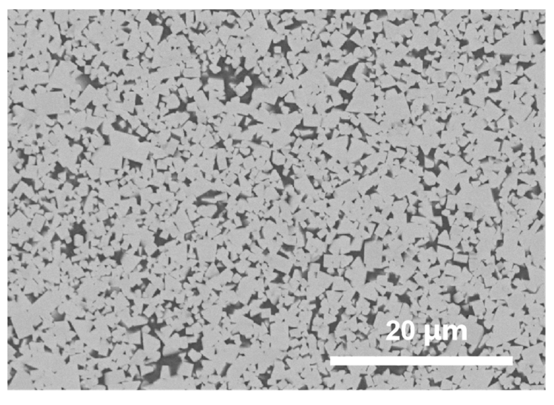
The morphology, particle size distribution and Raman spectrum test results of the feedstock diamond powder employed in this study (Zhecheng Huifeng Diamond Technology Co., Ltd., Shangqiu, China) are shown in Figure 1. The median particle size D50 of the diamond powder is 11μm. The feedstock diamond powder used in this study is the same batch of the regular diamond powder used in [15]. The average particle size of Co powder in this study (Shanghai ST-Nano Material Technology Co., Ltd., Shanghai, China) is 1μm, and the purity is 99.9%. The dimension of the WC-13 wt.% Co cemented carbide substrate (Zhuzhou Cemented Carbide Group Co., Ltd., Zhuzhou, China) is 16.5 mm diameter and 12 mm height, and the microstructure of the carbide substrate is shown in Figure 2. A flat PCD layer–carbide substrate interface was adopted in this study to remove any extra residual stress possibly caused by interface structure design.

2.2. Experimental Methods

2.2.1. Preparation of Initial Powder of PDCs

As shown in Table 1, the composition design of PCD layer in this study includes four different Co contents ranging from 13 to 30 wt.%. During the diamond–Co powder milling process, anhydrous ethanol was used as the dispersing medium. A horizontal ball mill (LHK-1.5-I, Haoqiang Machinery Factory, Yixing, China) was used for powder milling. A 4 mm diameter YG6 (WC-6 wt.% Co) milling ball was used and the ball/powder ratio was 1:1. The milling speed was 120 rpm and the milling time was 4 h. Then, the mixed diamond–Co powders were dried in a rotary evaporation instrument (RE-52C, Shanghai Leighton Industrial Co., Ltd., Shanghai, China), and purified in vacuum (5 × 10⁻³ Pa) at 500 °C for 1.5 h in a tube furnace (GSL-1500X-OTF, Hefei Kejing Material Technology Co., Ltd., Hefei, China).

2.2.2. HPHT Process

In this study, cubic press (CS-6X29500KN, Guilin Guiye Machinery Co., Ltd., Guilin, China) was used for the HPHT synthesis process. The above purified diamond–Co powder mixture and cemented carbide substrate were encapsulated in niobium and molybdenum cups, and then assembled into a pyrophyllite composite block, which was then put into a cubic press for HPHT process. The sintering temperature was 1580℃ and pressure was 5.5 GPa. The encapsulation and HPHT processes used in this study are similar to those adopted in [15,23]. The selection of sintering temperature and pressure is to ensure the melting of Co and the thermal stability of diamond during the HPHT process. The HPHT process can have an apparent effect on the residual stress of PDCs, while in this study, the research focus is the Co content of PCD layer, so only a set of commonly used HPHT process has been employed according to the general synthesis routine in PDC manufacturing industry. After HPHT process, the PDCs were removed from the pyrophyllite composite block, the metal cups on the surface of the PDCs were removed by sand blasting, and then the PDCs were finally cleaned and dried for further testing.

2.2.3. Residual Stress Evaluation

In this study, the residual stress of PDCs was determined via the position shift of the characteristic diamond peak from its stress-free position in Raman spectrum per the following equation [12,13]:
σ = v 0 v α
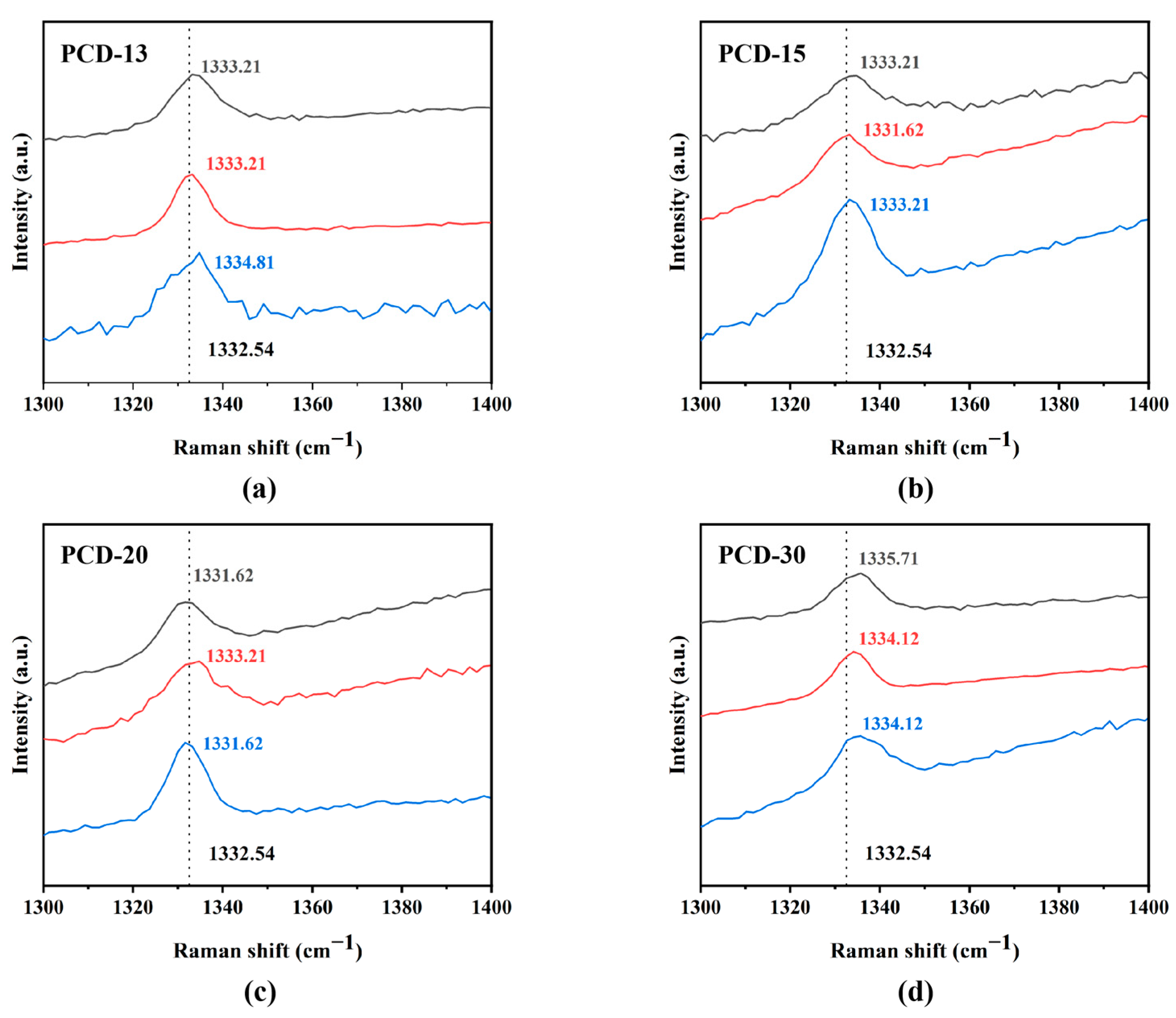
where σ is the residual stress at the test point (positive value means tensile residual stress and negative value means compressive residual stress), v 0 is the wave number of characteristic diamond peak without any residual stress, v is the measured wave number of characteristic diamond peak at the testing point, and α is the stress deviation coefficient, which is taken as 1.92 cm−1/GPa according to [26]. In this study, v 0 was taken as 1332.54 cm−1, corresponding to the wave number of stress free diamond powder in Figure 1c.

2.2.4. Property Characterization of Diamond Powder and Microstructure Analysis of PDCs

In this study, the particle size of the feedstock diamond powder was measured by laser particle size analyzer (Malvern, Mastersizer 3000). For HPHT-processed PDCs, metallographic samples were made by first EDM cutting the PDCs into half and then mounting the sectioned sample with bakelite. The mounted samples were then ground with 50 micron diamond slurry. The ground samples were then, respectively, polished with the 20, 10, 6, 3, and 1 micron diamond pastes in sequence. Field emission scanning electron microscopy (Hitach, SU8220) was used to analyze the morphology of the diamond powder and the microstructure of PDCs. Raman spectra of both diamond powder and PDCs were made by HORIBA Jobin Yvon (LabRAM HR Evolution) confocal Raman spectrometer. The metallographic samples of PDCs were prepared by a single-sided lapping machine (SS-15H, Lemat Walters (Shenyang) Precision Machinery Co., Ltd., Shenyang, China) and polishing equipment (Buehler, MetaServ 250).

2.3. FEM Simulation of Residual Stress

In this study, the residual stress was investigated based on the real-time simulation of the temperature field evolution of PDCs and the shrinkage behavior of PCD layer and cemented carbide substrate during the cooling stage. It is generally believed that the uneven distribution of temperature and the difference of physical parameters such as thermal expansion coefficient and elastic modulus between PCD layer and carbide substrate result in the residual stress of PDCs. According to Fourier heat transfer law and energy conservation law, the thermal conduction equation of the object can be described as [27]
x ( k x T x ) + y ( k y T y ) + z ( k z T z ) + ρ Q = ρ C p T t
where ρ is the density, C p the specific heat, k is the thermal conductivity, T is temperature, t is time, x–z are 3 directions, and Q is the thermal intensity inside the object.
The thermal strain caused by differences in material properties can be expressed as [27]
ε t h = α T · T ( x , y , z )
where is ε t h thermal strain, α T is coefficient of thermal expansion, and T ( x , y , z ) is thermal gradient.
Based on the thermal strain information per Equation (3), the residual stress of PDCs was calculated by generalized Hooke’s law.
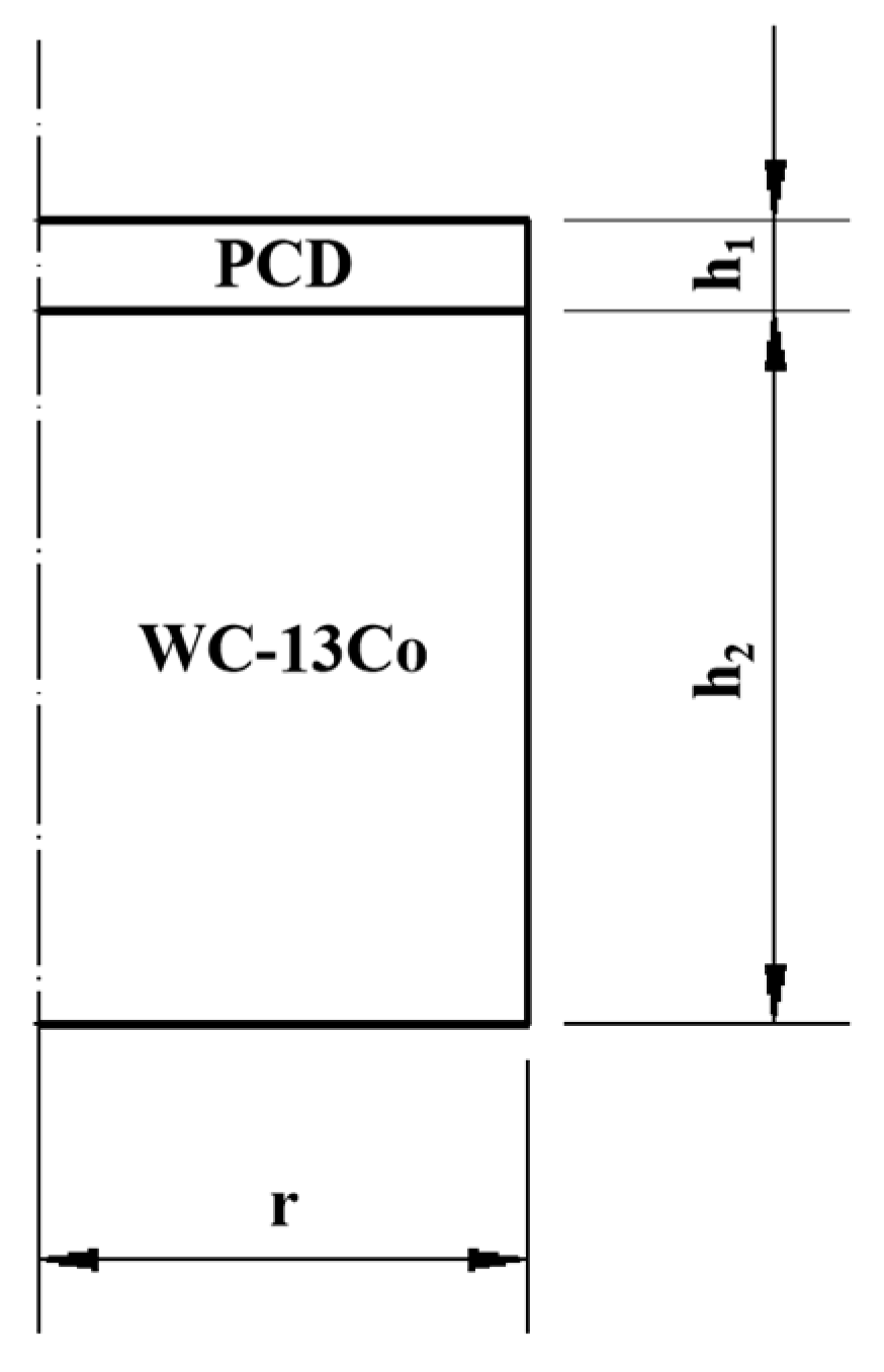
As shown in Figure 3, an axisymmetrical PDC model was established in this study to simulate the residual stress evaluation during the cooling stage. The simulation details will be given in the experimental results and discussion section.
The physical properties of diamond, cobalt and carbide substrate used in the FEM simulation in this study are shown in Table 2.
Since the PCD layer itself is a diamond–cobalt composite, the physical properties of the PCD layer for FEM simulation were calculated by the equivalent principle formula [29]. The equivalent physical properties of PCD layers with different cobalt contents and the dimensions of PDCs (Figure 3) are shown in Table 3. It should be mentioned that for experimental testing, only four kinds of PDCs have been synthesized, i.e., PDC-13, 15, 20, and 30, while for FEM simulation, many more PDCs with different Co contents (0–50 wt.%) have been utilized in order to make a more systematic investigation of the effect of Co content of PCD layers.

3. Experimental Results and Discussion

3.1. Microstructure of the PDCs

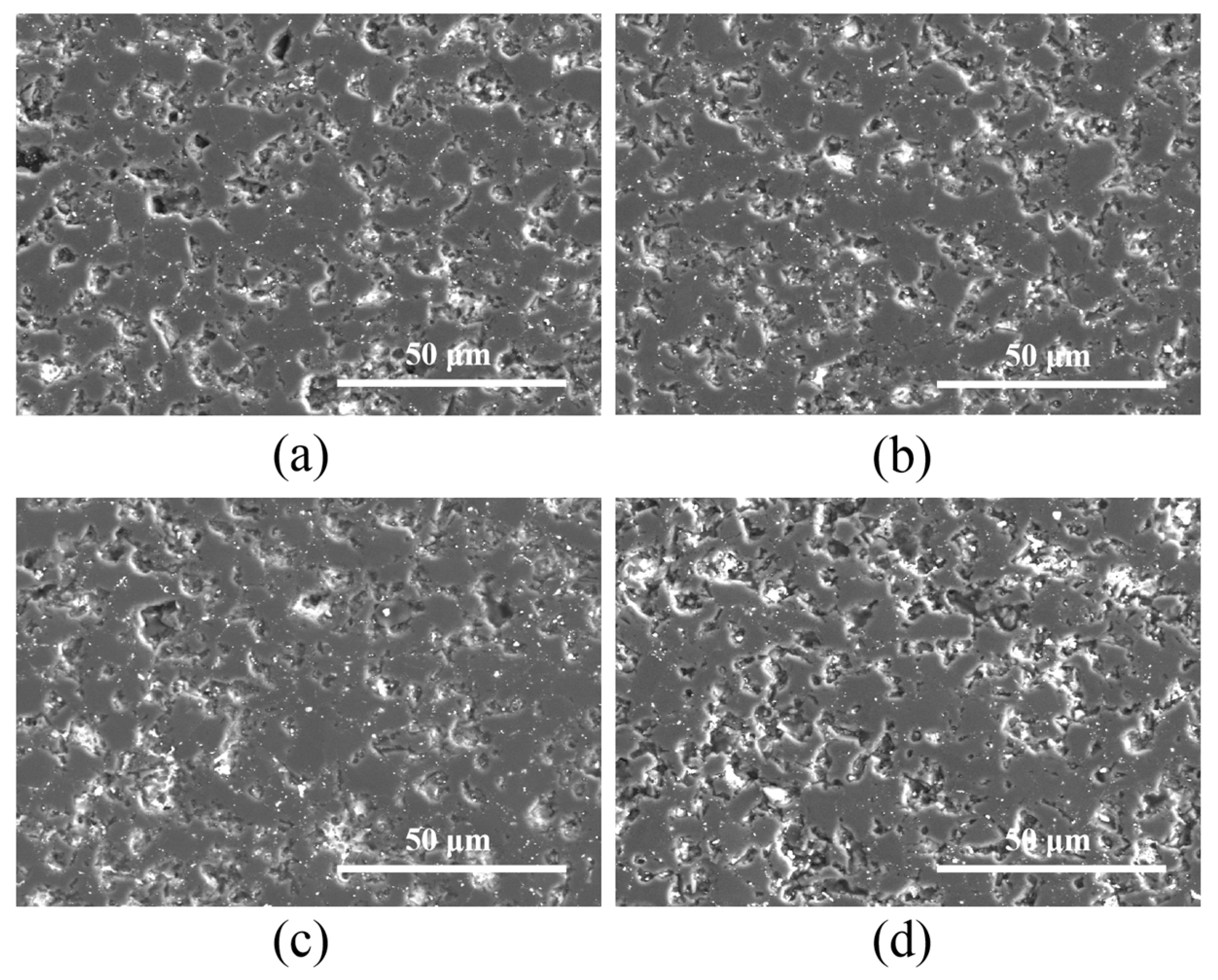
The microstructure of the PCD layer of the PDCs is shown in Figure 4, in which the gray region is a diamond phase, and the bright region and the concave pore-like region are actually a Co phase, which was almost totally removed during the polishing process and looks like pores. The pore-like Co phase was quite commonly observed in polished PDC samples [30] due to the extremely significant hardness difference between the diamond and Co phases. It can be observed that after the HPHT process, the original diamond particles have formed an interconnected diamond skeleton structure in all four PDCs, and the Co phase is distributed in between the diamond skeleton structure.
The formation of a diamond skeleton in Figure 4 is mainly attributed to the diamond dissolution and re-precipitation process during the HPHT sintering process [1,5,6]. During the HPHT process, when the sintering temperature is over the melting point of Co, liquid Co will flow between diamond particles. Due to the thermal stability difference between finer and coarser diamond particles or between the sharp corner and flat surface (or concave surface, especially the diamond-diamond contact region) of diamond particles, the finer diamond particles and the sharp corner of diamond particles will dissolve into liquid Co first and then re-precipitate onto the coarser diamond particles or a flat or concave surface of diamond particles, resulting in the diamond grain growth as well as the flattening and connecting of diamond particles. Eventually, the interconnection of diamond particles (D-D bond) will happen between diamond particles to form the diamond skeleton in Figure 6 via Ostwald ripening [31]. Such a dissolution and re-precipitation process of diamond particles will happen only in liquid Co, Ni, or Fe due to their significant catalytic effect for carbon–diamond transformation processes.
The microstructure of the PCD–carbide substrate interface is shown in Figure 5. It can be observed that for PCD-13 and -15, there are clear interfaces between the PCD layer and carbide substrate, while for PCD-20 and -30, significant Co-enrichment regions exist at the PCD–carbide substrate interface. The formation of Co enrichment regions can also be explained by the dissolution and re-precipitation process of diamond particles during the HPHT process.
As shown in Figure 6, during the HPHT process, liquid Co will penetrate into the PCD layer from the carbide substrate under high pressure. Both the liquid Co penetrating into the PCD layer and the Co in the initial PCD layer will interact with the diamond powder to complete the above mentioned dissolution and re-precipitation process of diamond particles, resulting in a D-D bond and the growth of diamond particles into a skeleton structure [1,4,32]. With the growth of diamond particles becoming more and more significant and the gaps between the diamond skeleton structure becoming smaller, the extra Co between diamond particles will be expelled back to the carbide substrate, resulting in the reverse migration of Co. As compared with PCD-13 and 15, more Co in PCD-20 and 30 were involved in the dissolution-re-precipitation process of diamond particles and more significant reverse migration of Co will happen. Due to the fact that the carbide substrate cannot absorb the extra Co involved in reverse migration in a short sintering time, the Co-enrichment regions will form at the PCD–carbide substrate interface as shown in Figure 5. Compared with PCD-13 and 15, PCD-20 and 30 have noticeable Co-enrichment regions at the PCD–carbide substrate interface. The Co-enrichment region may enhance the bonding between the PCD layer and the carbide substrate. In addition, due to the significant CTE difference between diamond and Co, a Co-enrichment region can possibly alter the residual stress of a PCD layer, while up until now, related research has rarely been reported.

3.2. Raman Spectrum Analysis

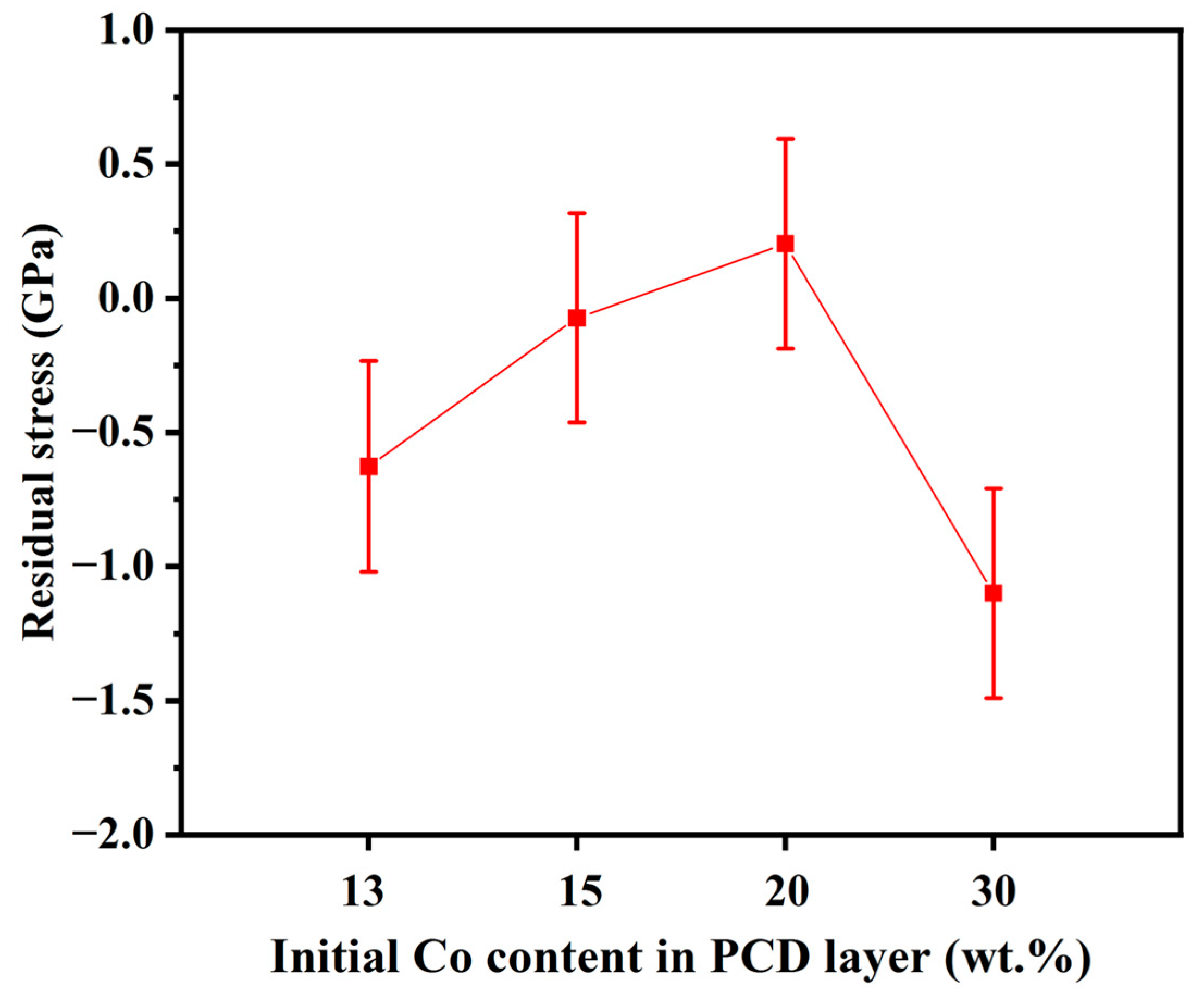
As shown in Figure 7, Raman spectroscopy was used to evaluate the characteristic diamond peaks at the center of the upper surface of the PCD layer of all the PDCs. The diamond peak around 1332.54 cm−1 has been observed and no graphite peaks appear for all the PDCs. The residual stress results calculated per Equation 1, based on the accurate diamond peak position in Figure 7, are shown in Figure 8. The residual stress at the center of the upper surface of the PCD layer of PCD-13 is compressive stress, and with the increase in Co content in the PCD layer, the compressive stress gradually decreases and turns into tensile stress when the Co content in the PCD layer is as high as 20 wt.% (PCD-20). A further increase in Co content results in significant compressive stress (PCD-30). Comprehensive FEM simulation has to be made in order to investigate the main reason for the abrupt transition of residual stress from tensile (PCD-20) to significant compressive (PCD-30).

3.3. FEM Simulation of Residual Stress for PDCs

It is generally believed that the residual stress of PDCs is mainly caused by the difference of the thermal expansion coefficient and Young’s modulus between the PCD layer and carbide substrate [10,12]. Based on the two-dimensional planar structure model commonly used in residual stress simulation, this study carried out FEM simulation of the residual stress. According to the actual synthesis process, the initial temperature for FEM was set to 1580 ℃, the ambient temperature was 25 °C, and the length of the analysis step was set to 480. The transient temperature-displacement coupling method was used for simulation calculation. The factors of the axisymmetric interface wedge condition were set to XSYMM, structured grid partitioning was used for meshing process, and the mesh cell type was set to CAX4T, which shows good mesh quality and high mesh sensitivity. In addition, the surface heat transfer coefficient of the upper and lower surfaces and sides of the PDCs was set to 0.042.
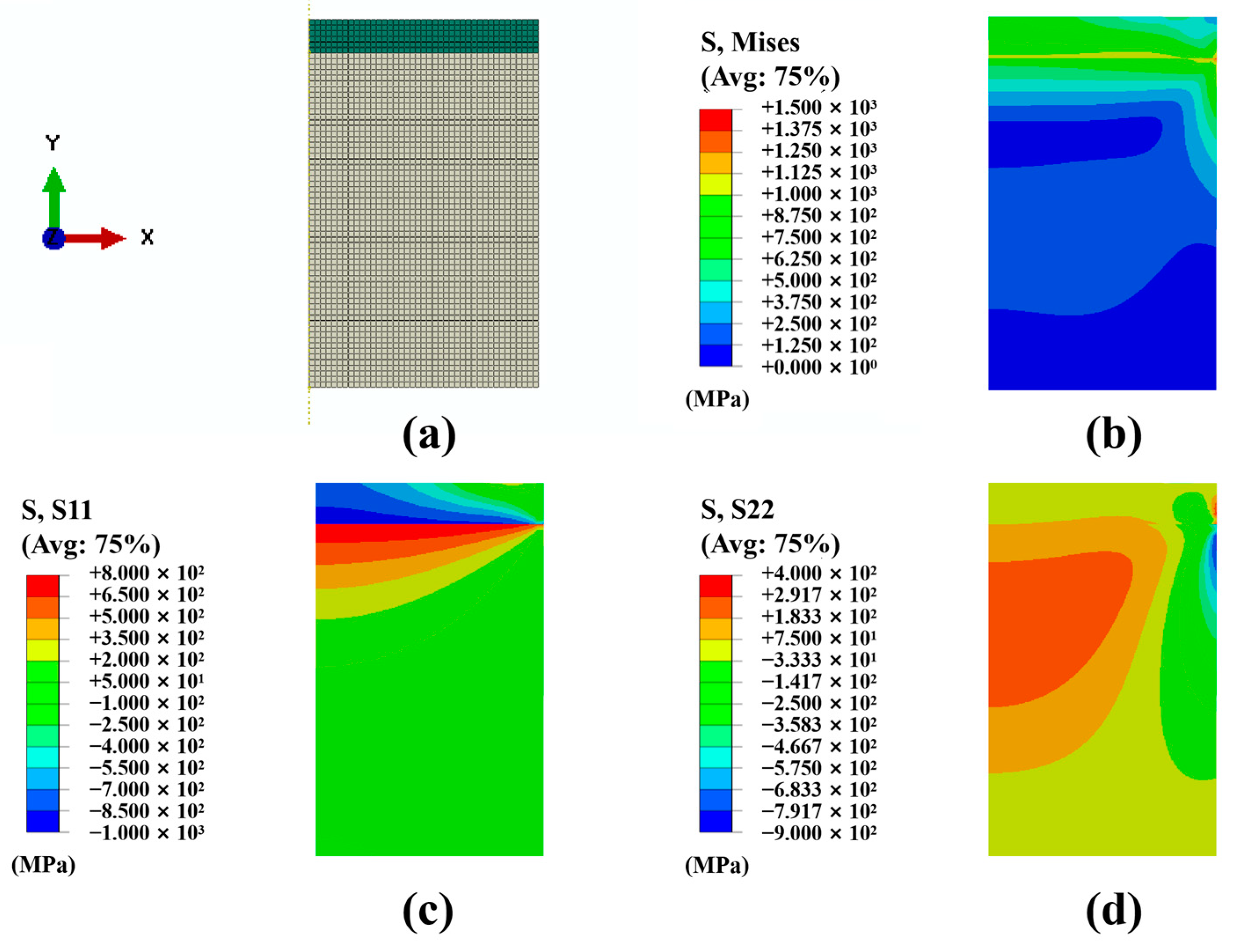
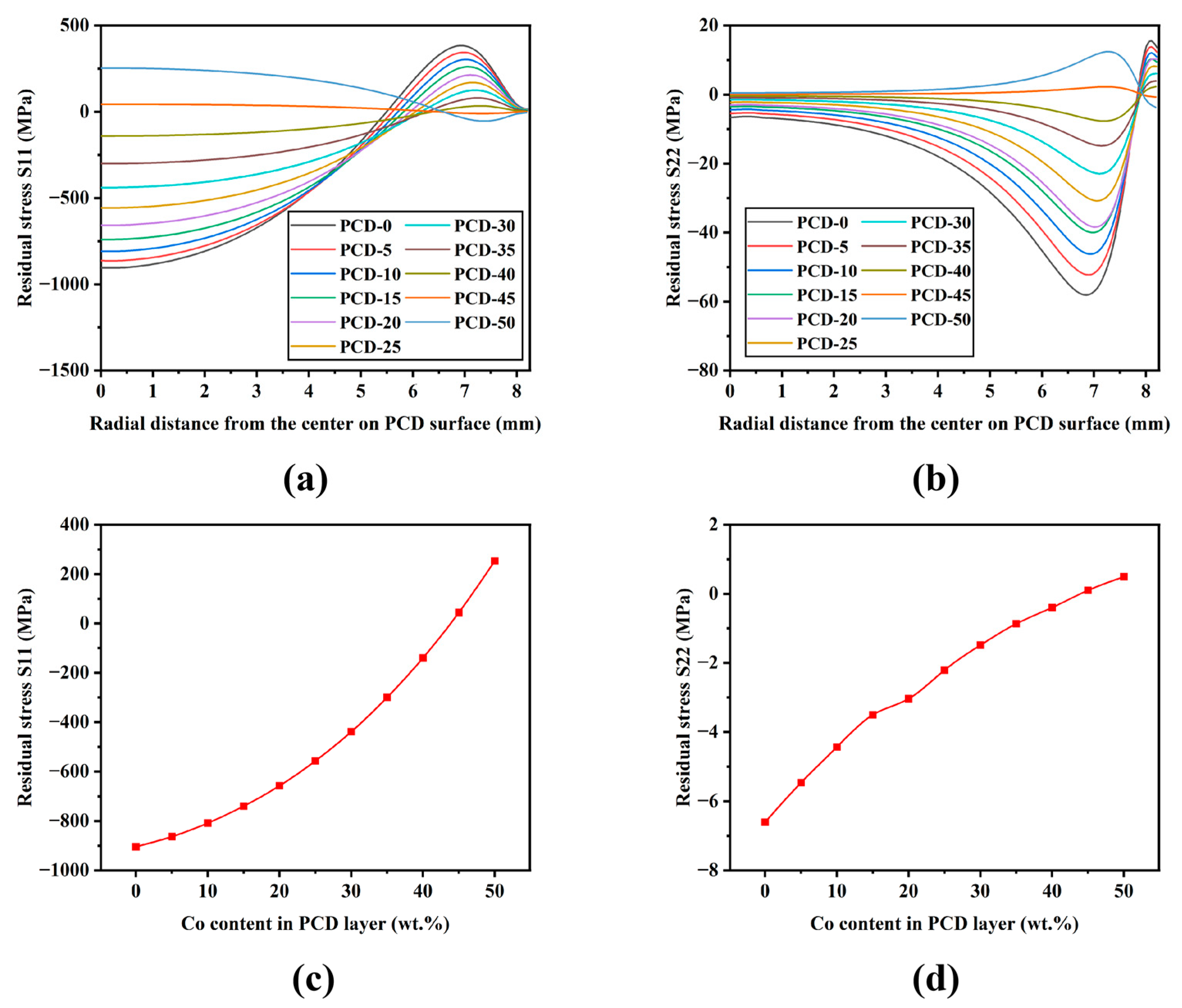
Figure 9 shows the mesh elements and residual stress (mises, S11 and S22) nephograms for PCD-15. Figure 10 shows the residual stress on the top surface of the PCD layer as the function of radial distance from the top center of the PCD layer (Figure 10a,b) as well as the residual stress at the center of the top surface of the PCD layer as the function of the Co content of the PCD layer (Figure 10c,d) for all the PDCs (PDC-0-50). The FEM results in this study shows the similar trends to the research results of CHEN et al. [10]. Figure 9 shows that the maximum stress is concentrated at the PCD–carbide substrate interface, and the stress is smaller at the positions away from the interface. Figure 10a,b shows that the horizontal radial residual stress (S11) is much more significant compared with the vertical axial stress in the PCD layer thickness direction (S22). Figure 10c,d shows that with the increase in Co content, both the radial stress S11 and axial stress S22 monotonically increases and changes from compressive stress to tensile stress, which is inconsistent with the experimental residual stress profile shown in Figure 8, where the residual stress transforms back into compressive stress from tensile stress when Co content is more than 20%.
From both experimental residual stress measurement and FEM simulation results, it can be seen that when the cobalt content in the PCD layer is low (0–15%), the residual compressive stress will form in the PCD layer after the HPHT process mainly due to the more significant shrinkage of the carbide substrate as compared with that of the PCD layer. With a further increase in Co content, the thermal expansion coefficient of the PCD layer continues to increase, and the Young’s modulus continues to decrease, so the thermal and elastic property difference between the PCD layer and carbide substrate decreases, leading to the decrease in residual compressive stress of the PCD layer and the transformation of compressive stress into tensile stress. However, when the Co content is greater than 20 wt.%, Figure 8 shows that the experimental residual stress of the PCD layer transforms abruptly from tensile stress back into compressive stress again, while the FEM simulation in Figure 10 shows that the residual compressive stress monotonically decreases with the increase in Co content of the PCD layer and gradually develops into tensile stress when the Co content of the PCD layer is high enough, but there is no transformation of tensile stress back into compressive stress. From the inconsistency trends between the experimental residual stress and the FEM simulation results, it can be inferred that the difference of physical properties between the PCD layer and carbide substrate is not the only factor affecting the residual stress evolution behavior of PDCs. In addition, it should be noticed that the traditional FEM method (Figure 9 and Figure 10) takes the whole PCD layer (diamond + Co) as a unit and cannot reveal the residual stress of the diamond phase, which can be another reason for the inconsistency trends between the experimental residual stress and the FEM simulation results. In order to investigate the actual residual stress of the diamond phase, a micromechanical simulation based on the microstructure of PDCs was employed in this study.

3.4. Micromechanical Simulation Based on Microstructure of PCD–Carbide Substrate Interface

As shown in Figure 5, when the Co content is more than 20 wt.%, there is a noticeable reverse migration of Co from the PCD layer to carbide substrate, resulting in a Co enrichment region at the PCD–carbide interface. The Co enrichment region may contribute to the transformation of residual stress of the diamond phase from tensile into compressive stress for PDC-30. In order to reveal the micromechanism of residual stress evolution, micromechanical simulation was carried out based on the actual microstructure of the PCD–carbide substrate interface.
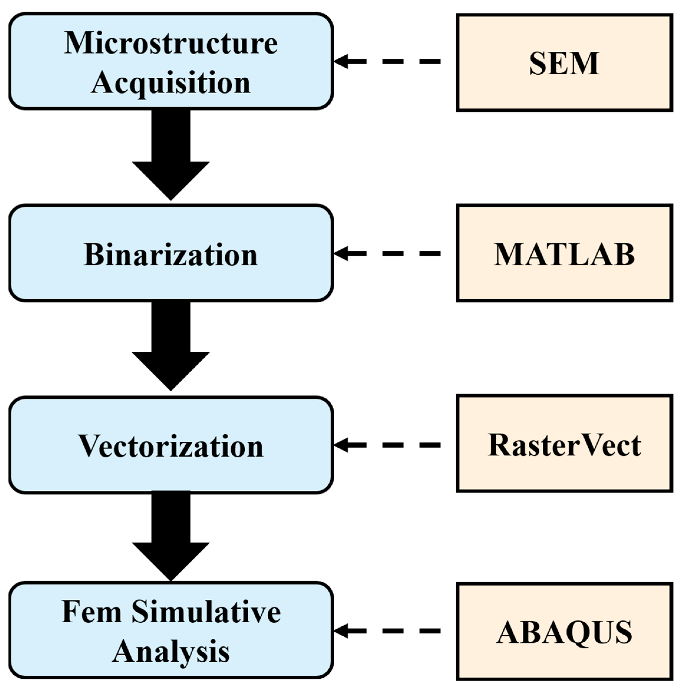
As shown in Figure 11, the specific micromechanical simulation process was based on the PCD–carbide substrate interface microstructure of PDCs. The microstructure was first binarized by MATLAB software, and then vectorized by RasterVect software. Finally, the vectorized file was imported into ABAQUS finite element simulation software to establish a simulation model.
Figure 12 is the SEM micrograph of the PCD–carbide substrate interface of PCD-15, PCD-20 and PCD-30. According to the procedure in Figure 11, the SEM micrographs of PCD-15, PCD-20 and PCD-30 were binarized and vectorized, and the finite element simulation models were shown in Figure 13, where the unique role of the Co-enrichment region was emphasized. The static general method was used for simulation calculation. Free meshing was adopted to address the complicated microstructure feature, and the mesh cell type was set to CPS4R. Mesh analysis shows that both the error rate and warning rate of all the meshes are 0%.
Figure 14 is the residual stress nephogram in X (S11) and Y-axis (S22) based on the actual microstructure in Figure 12. The positive means tensile stress, while the negative means compressive stress. It can be observed that the Co-enrichment region is subjected to clearly tensile stress. Compared with PCD-15, there is more evident compressive stress of the diamond phase in PCD-20 and 30.
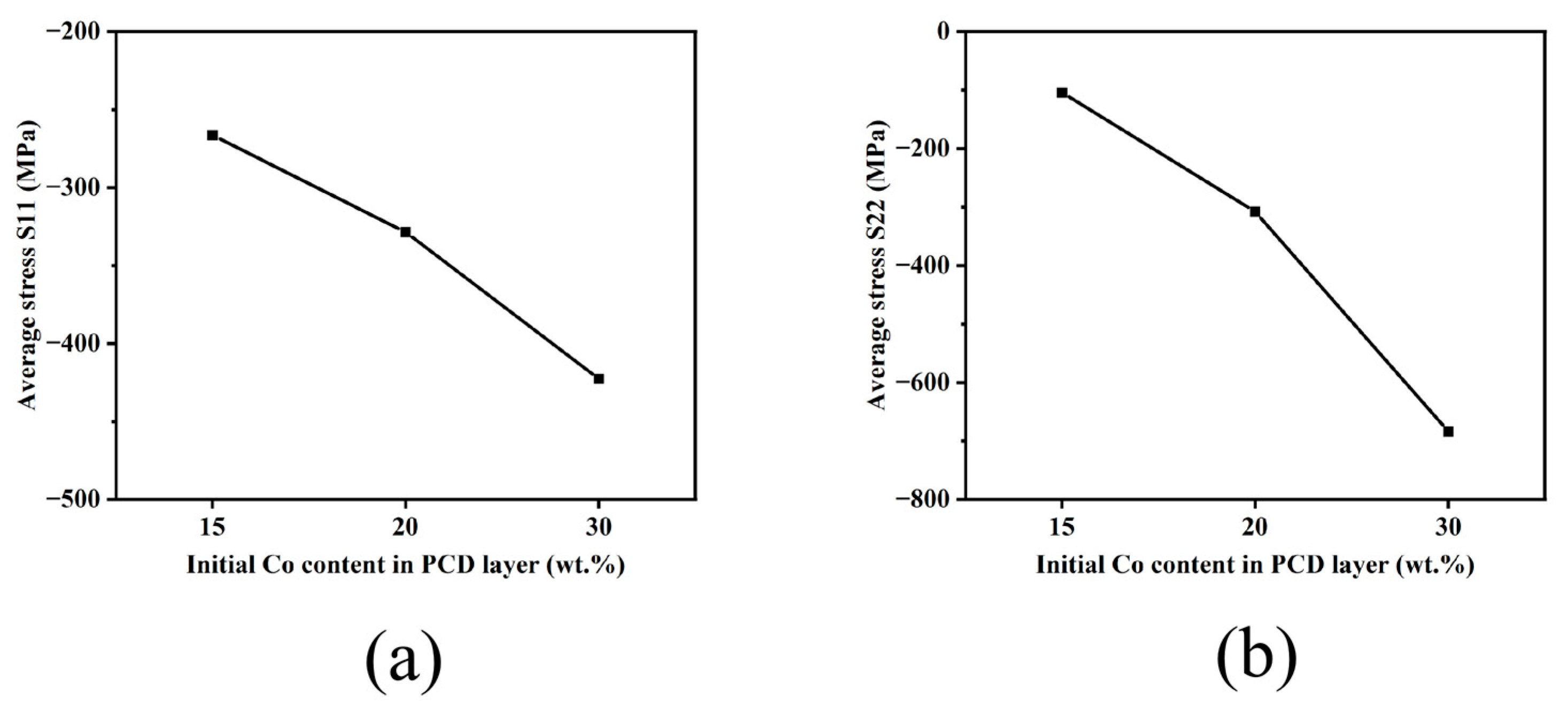
Figure 15 shows the statistically average stress of the diamond phase based on the residual stress results in Figure 14. It can be observed that the average stress of the diamond phase is compressive and the compressive stress increases with the Co content in the PCD layer, which is completely opposite to the trend in Figure 10c,d. It can be inferred from Figure 15 that when the actual microstructure of the PCD–cemented carbide interface, especially the Co enrichment region, is included in FEM simulation, the evolution trend of residual stress is significantly different from the traditional FEM (without considering the effect of the Co enrichment region) in Figure 9 and Figure 10. The results show that the Co-enrichment region at the PCD–cemented carbide interface introduces significant compressive residual stress to the diamond phase.
Per a comprehensive comparison of the traditional axisymmetric simulation model (Figure 9) and the micromechanical simulation model based on interfacial microstructure (Figure 14), it can be found that the residual stress of the diamond phase in PDCs is the combination result of both the macro-scale stress caused by physical property differences between the PCD layer and the carbide substrate and the micro-scale stress caused by physical property differences between the diamond phase and the Co-enrichment region. When the Co content of the PCD layer is lower than 20 wt.%, the residual stress of diamond is mainly affected by the physical property difference between the PCD layer and carbide substrate, demonstrating clearly a compression state. When Co content of the PCD layer is increased to 20 wt.%, the thermal expansion coefficient of the PCD layer gradually increases from a level significantly below the carbide substrate to a level slightly higher than the carbide substrate, and the compressive residual stress of diamond becomes slightly tensile stress. When the Co content of the PCD layer is more than 20 wt.%, the Co enrichment region at the PCD–carbide substrate interface exerts a significant compressive stress on the diamond phase (Figure 15), resulting in the transformation of tensile stress back into compressive stress of the diamond phase shown in Figure 8.
In spite of the fact that micro-mechanical simulation is only based on a very small region due to the limitation of the calculation resource, Figure 14 and Figure 15 demonstrate the critical role of the Co-enrichment region on the residual stress evolution of the diamond phase, especially for PDCs with high Co content of PCD layers. Moreover, both Figure 8 and Figure 15 show that the Co content of the PCD layer is critical to the residual stress of the diamond phase, which has rarely been reported before.

4. Conclusions

Based on the above study, it can be found that the Co content of PCD layers, as well as the Co-enrichment region at PCD–carbide interfaces are critical to the residual stress evolution of diamond phases following the HPHT process. This study shows that, by optimizing the PCD layer material design and tailoring the microstructure of the PCD–carbide interface, it can be highly possible to precisely manipulate the residual stress of PDCs in order to improve the lifetime and stability of PDCs in various applications. The conclusions in this study include:
(1) For HPHT-processed PDCs, the Co content of the PCD layer is found to have a significant effect on the microstructure evolution of PDCs. When the Co content of the PCD layer is lower than 20 wt.%, the microstructure of both the PCD layer and carbide substrate are homogeneous without any noticeable phase segregation. When the Co content of the PCD layer is more than 20 wt.%, there is noticeable reverse migration of Co from the PCD layer to the carbide substrate, resulting in the prevalent Co-enrichment regions at the PCD–carbide substrate interface.
(2) The Co content of the PCD layer is critical to the residual stress evolution of the diamond phase in PDCs. When the Co content of the PCD layer is lower than 20 wt.%, the residual stress of the diamond phase at the center of the upper surface of the PCD layer is compressive. With the increase in Co content, the residual compressive stress gradually decreases and even develops into tensile stress. When the Co content is more than 20 wt.%, the tensile residual stress transforms back into a significant compressive stress.
(3) The wide spread Co-enrichment region at the PCD–carbide substrate of PDC with 30 wt.% Co of the PCD layer is the main reason for the transformation of residual stress of the diamond phase from tensile back into compressive.

Author Contributions

Conceptualization, P.N. and X.D.; data curation, W.Y.; formal analysis, Z.H.; funding acquisition, X.D.; investigation, P.N., Y.C. and W.Y.; methodology, P.N. and Y.C.; project administration, X.D.; resources, X.D.; supervision, X.D.; writing—original draft, P.N.; writing—review and editing, Y.C. and X.D. All authors have read and agreed to the published version of the manuscript.

Funding

This research was funded by Foshan Science and Technology Innovation Team project (FS0AA-KJ919-4402-0023), and Jihua Laboratory Project (Grant No. X190061UZ190).

Data Availability Statement

The data presented in this study are available on request from the corresponding author.

Acknowledgments

The authors appreciate the financial support from Foshan Science and Technology Innovation Team project (Grant No.: FS0AA-KJ919-4402-0023), and Jihua Laboratory Project (Grant No.: X190061UZ190).

Conflicts of Interest

The authors declare no conflict of interest.

References

  1. Wentorf, R.H.; Devries, R.C.; Bundy, F.P. Sintered superhard materials. Science 1980, 208, 873. [Google Scholar] [CrossRef] [PubMed]
  2. Li, G.; Rahim, M.Z.; Pan, W.; Wen, C.; Ding, S. The manufacturing and the application of polycrystalline diamond tools—A comprehensive review. J. Manuf. Process. 2020, 56, 400. [Google Scholar] [CrossRef]
  3. Miyazaki, K.; Ohno, T.; Karasawa, H.; Takakura, S.; Eko, A. Performance evaluation of polycrystalline diamond compact percussion bits through laboratory drilling tests. Int. J. Rock Mech. Min. Sci. 2016, 87, 1. [Google Scholar] [CrossRef]
  4. Bochechka, O.O. Production of Polycrystalline Materials by Sintering of Nanodispersed Diamond Nanopowders at High Pressure. Review. J. Superhard Mater. 2018, 40, 325. [Google Scholar] [CrossRef]
  5. Miess, D.; Rai, G. Fracture toughness and thermal resistance of polycrystalline diamond compacts. Mater. Sci. Eng. A 1996, 209, 270. [Google Scholar] [CrossRef]
  6. Clark, I.; Bex, P. The use of PCD for petroleum and mining drilling. Ind. Diam. Rev. 1999, 59, 43. [Google Scholar]
  7. Abbas, R.K.; Musa, K.M. Using Raman shift and FT-IR spectra as quality indices of oil bit PDC cutters. Petroleum 2019, 5, 329. [Google Scholar] [CrossRef]
  8. Bellin, F.; Dourfaye, A.; King, W.; Thigpen, M. The current state of PDC bit technology. World Oil 2010, 231, 53. [Google Scholar]
  9. Kim, D.; Beal, A.; Kwon, P. Effect of Tool Wear on Hole Quality in Drilling of Carbon Fiber Reinforced Plastic-Titanium Alloy Stacks Using Tungsten Carbide and Polycrystalline Diamond Tools. J. Manuf. Sci. Eng.-Trans. Asme 2016, 138, 031006. [Google Scholar] [CrossRef]
  10. Chen, F.; Xu, G.; Ma, C.; Xu, G. Thermal residual stress of polycrystalline diamond compacts. Trans. Nonferrous Met. Soc. China 2010, 20, 227. [Google Scholar] [CrossRef]
  11. Paggett, J.; Drake, E.; Krawitz, A.; Winholtz, R.; Griffin, N. Residual stress and stress gradients in polycrystalline diamond compacts. Int. J. Refract. Met. Hard Mater. 2002, 20, 187. [Google Scholar] [CrossRef]
  12. McNamara, D.; Alveen, P.; Damm, S.; Carolan, D.; Rice, J.H.; Murphy, N.; Ivanković, A. A Raman spectroscopy investigation into the influence of thermal treatments on the residual stress of polycrystalline diamond. Int. J. Refract. Met. Hard Mater. 2015, 52, 114. [Google Scholar] [CrossRef]
  13. Erasmus, R.M.; Comins, J.D.; Mofokeng, V.; Martin, Z. Application of Raman spectroscopy to determine stress in polycrystalline diamond tools as a function of tool geometry and temperature. Diam. Relat. Mater. 2011, 20, 907. [Google Scholar] [CrossRef]
  14. Yue, T.; Yue, W.; Li, J.; Wang, C. Effect of vacuum annealing temperature on tribological behaviors of sintered polycrystalline diamond compact. Int. J. Refract. Met. Hard Mater. 2017, 64, 66. [Google Scholar] [CrossRef]
  15. Ni, P.; Zhao, Z.; Yang, W.; Deng, X.; Wu, S.; Qu, Z.; Jin, F. Effect of feedstock diamond powder property on microstructure and mechanical properties of polycrystalline diamond compacts. Int. J. Refract. Met. Hard Mater. 2023, 111, 106102. [Google Scholar] [CrossRef]
  16. Gu, J.; Huang, K.J.D.; Materials, R. Role of cobalt of polycrystalline diamond compact (PDC) in drilling process. Diam. Relat. Mater. 2016, 66, 98. [Google Scholar] [CrossRef]
  17. Kong, C.; Liang, Z.; Zhang, D.J.M. Failure analysis and optimum structure design of PDC cutter. Mechanics 2017, 23, 567. [Google Scholar] [CrossRef]
  18. Lin, T.; Hood, M.; Cooper, G.A.; Smith, R.H. Residual stresses in polycrystalline diamond compacts. J. Am. Ceram. Soc. 1994, 77, 1562. [Google Scholar] [CrossRef]
  19. Vhareta, M.; Erasmus, R.M.; Comins, J.D. Investigation of fatigue-type processes in polycrystalline diamond tools using Raman spectroscopy. Diam. Relat. Mater. 2014, 45, 34. [Google Scholar] [CrossRef]
  20. Yadav, V.; Jain, V.K.; Dixit, P.M. Thermal stresses due to electrical discharge machining. Int. J. Mach. Tools Manuf. 2002, 42, 877. [Google Scholar] [CrossRef]
  21. Catledge, S.A.; Vohra, Y.K.; Ladi, R.; Rai, G. Micro-Raman stress investigations and X-ray diffraction analysis of polycrystalline diamond (PCD) tools. Diam. Relat. Mater. 1996, 5, 1159. [Google Scholar] [CrossRef]
  22. Rats, D.; Bimbault, L.; Vandenbulcke, L.; Herbin, R.; Badawi, K.F. Crystalline quality and residual stresses in diamond layers by Raman and x-ray diffraction analyses. J. Appl. Phys. 1995, 78, 4994. [Google Scholar] [CrossRef]
  23. Krawitz, A.D.; Winholtz, R.A.; Drake, E.F.; Griffin, N. Residual stresses in polycrystalline diamond compacts. Int. J. Refract. Met. Hard Mater. 1999, 17, 117. [Google Scholar] [CrossRef]
  24. Mukhopadhyay, D. Identifying the causes of residual stress in polycrystalline diamond compact (PDC) cutters by X-ray diffraction technique. Results Mater. 2021, 11, 100216. [Google Scholar] [CrossRef]
  25. Chen, Z.; Ma, D.; Wang, S.; Dai, W.; Li, S.; Zhu, Y.; Liu, B. Effects of graphene addition on mechanical properties of polycrystalline diamond compact. Ceram. Int. 2020, 46, 11255. [Google Scholar] [CrossRef]
  26. Prawer, S.; Nemanich, R.J. Raman spectroscopy of diamond and doped diamond. Philos. Trans. R. Soc. Lond. Ser. A-Math. Phys. Eng. Sci. 2004, 362, 2537. [Google Scholar] [CrossRef]
  27. Zeng, P. Fundamentals of Finite Element Analysis; Higher Education Press: Beijing, China, 2009; p. 290. [Google Scholar]
  28. Kanyanta, V.; Ozbayraktar, S.; Maweja, K. Effect of manufacturing parameters on polycrystalline diamond compact cutting tool stress-state. Int. J. Refract. Met. Hard Mater. 2014, 45, 147. [Google Scholar] [CrossRef]
  29. Zhu, J.; Zhou, H.; Qin, B.; Zhao, Z. Design, fabrication and properties of TiB2/TiN/WC gradient ceramic tool materials. Ceram. Int. 2020, 46, 6497. [Google Scholar] [CrossRef]
  30. Shin, T.; Oh, J.; Oh, K.H.; Lee, D.N. The mechanism of abnormal grain growth in polycrystalline diamond during high pressure-high temperature sintering. Diam. Relat. Mater. 2004, 13, 488. [Google Scholar] [CrossRef]
  31. Vengrenovitch, R.D. On the ostwald ripening theory. Acta Metall. 1982, 30, 1079. [Google Scholar] [CrossRef]
  32. Kanyanta, V. Microstructure-Property Correlations for Hard, Superhard, and Ultrahard Materials; Springer: London, UK, 2016; p. 35. [Google Scholar]
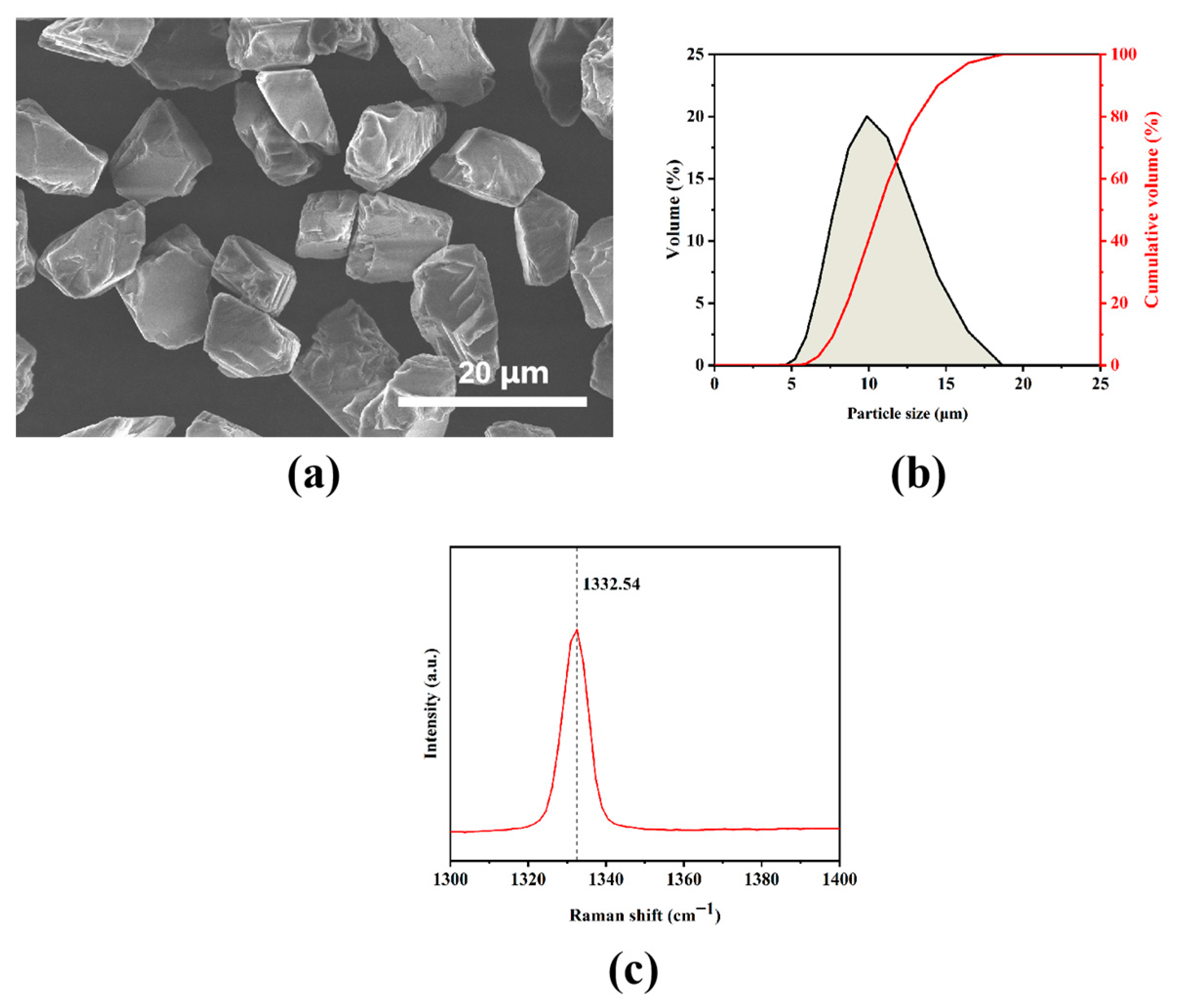
Figure 1. Characterization of feedstock diamond powder, (a) diamond powder morphology, (b) particle size distribution, and (c) Raman spectrum.
Crystals 13 01286 g001
Figure 2. Microstructure of WC-13 wt.% Co carbide substrate.
Crystals 13 01286 g002
Figure 3. Schematic of the axisymmetric structure of PDCs for FEM simulation.
Crystals 13 01286 g003
Figure 4. Microstructure of PCD layers for PDCs, (a) PCD-13, (b) PCD-15, (c) PCD-20, and (d) PCD-30.
Crystals 13 01286 g004
Figure 5. Microstructure of PCD-carbide interface of PDCs, (a) PCD-13, (b) PCD-15, (c) PCD-20 and (d) PCD-30.
Crystals 13 01286 g005
Figure 6. Schematic of PDC sintering process, (a) initial stage, (b) infiltration of Co from carbide substrate, and (c) reverse migration of Co.
Crystals 13 01286 g006
Figure 7. Raman spectra of the center of upper surface of PCD layer for PDCs, (a) PCD-13, (b) PCD-15, (c) PCD-20, and (d) PCD-30.
Crystals 13 01286 g007
Figure 8. Residual stress of diamond phase at the center of upper surface of PCD layer for PDCs as the function of Co content of PCD layer.
Crystals 13 01286 g008
Figure 9. FEM for PCD-15, (a) mesh elements, and distribution of residual stresses including (b) Mises, (c) S11, and (d) S22.
Crystals 13 01286 g009
Figure 10. FEM residual stress (a) S11 and (b) S22 of the upper surface of PCD layers as the function of radial distance from the center of PCD surface, and FEM residual stress (c) S11 and (d) S22 of the center of upper surface of PCD layer as the function of Co content of PCD layer.
Crystals 13 01286 g010
Figure 11. Micromechanical simulation procedure based on microstructure of PCD–carbide interface.
Crystals 13 01286 g011
Figure 12. Microstructure of PCD–carbide substrate interface, (a) PCD-15, (b) PCD-20, and (c) PCD-30.
Crystals 13 01286 g012
Figure 13. Simulation models and meshing of PDCs based on the actual microstructure in Figure 12, (a) PCD-15, (b) PCD-20, and (c) PCD-30, and meshing of (d) PCD-15, (e) PCD-20, and (f) PCD-30.
Crystals 13 01286 g013
Figure 14. S11 (ac) and S22 (df) distributions at PCD–carbide interface based on the actual microstructure of PDCs, (a,d) PCD-15, (b,e) PCD-20, and (c,f) PCD-30.
Crystals 13 01286 g014
Figure 15. The average (a) S11 and (b) S22 of diamond phase in Figure 14 as the function of Co content of PCD layer.
Crystals 13 01286 g015
Table 1. Composition design of PCD layer for PDCs synthesized in this study.
PDC DesignationDiamond Powder Content, wt.%Co powder Content, wt.%
PCD-138713
PCD-158515
PCD-208020
PCD-307030
Table 2. Physical properties of the constituents of PDCs for FEM simulation [10,12,28].
PropertyDiamondCobaltCarbide Substrate
Elastic modulus (GPa), E 900200579
Density (kg/m3), ρ 3500850015000
Poisson’s ratio, υ 0.070.330.22
Thermal conductivity (W/(m·K)), k200069.2100
Specific Heat (J/(kg·K)), C p 471440230
Coefficient of thermal expansion (10−6·K−1), α3.214.45.2
Table 3. Physical properties of PCD layer and the dimension of PDCs (Figure 3) for FEM simulation.
Designation of PDCs (Number Corresponds to wt.% of Co in PCD Layer)Dimension of PDCs in Figure 3 ρ
(kg/m3)
E
(GPa)
υ
 
α
(10−6·K−1)
C
(J/(kg·K))
k
(W/(m·K))
r
(mm)
h 1
(mm)
h 2
(mm)
PCD-08.251.645123500.000900.0000.0703.200471.0002000.000
PCD-58.251.597123606.061877.7620.0763.362470.3421921.703
PCD-108.251.548123718.750854.6770.0823.536469.6441841.776
PCD-158.251.500123838.710830.6930.0893.724468.9001760.166
PCD-208.251.452123966.667805.7570.0963.928468.1071676.821
PCD-258.251.403124103.448779.8080.1034.150467.2591591.684
PCD-308.251.355124250.000752.7810.1104.393466.3501504.697
PCD-358.251.306124407.407724.6060.1194.659465.3741415.799
PCD-408.251.258124576.923695.2040.1274.952464.3231324.926
PCD-458.251.210124760.000664.4880.1375.276463.1881232.012
PCD-508.251.161124958.333632.3630.1475.637461.9581136.986
Disclaimer/Publisher’s Note: The statements, opinions and data contained in all publications are solely those of the individual author(s) and contributor(s) and not of MDPI and/or the editor(s). MDPI and/or the editor(s) disclaim responsibility for any injury to people or property resulting from any ideas, methods, instructions or products referred to in the content.