Abstract
Research has been conducted on solid oxide fuel cells (SOFCs) for their fuel flexibility, modularity, high efficiency, and power density. However, the high working temperature leads to the deterioration of materials and increased operating costs. Considering the high protonic conductivity and low activation energy, the proton conducting SOFC, i.e., the protonic ceramic fuel cell (PCFC), working at a low temperature, has been wildly investigated. The PCFC is a promising state-of-the-art electrochemical energy conversion system for ecological energy; it is characterized by near zero carbon emissions and high efficiency, and it is environment-friendly. The PCFC can be applied for the direct conversion of various renewable fuels into electricity at intermediate temperatures (400–650 °C). The construction of the PCFC directly affect its properties; therefore, manufacturing technology is the crucial factor that determines the performance. As a thinner electrolyte layer will lead to a lower polarization resistance, a uniformly constructed and crack-free layer which can perfectly bond to electrodes with a large effective area is challenging to achieve. In this work, different fabrication methods are investigated, and their effect on the overall performance of PCFCs is evaluated. This article reviews the recent preparation methods of PCFCs, including common methods, 3D printing methods, and other advanced methods, with summarized respective features, and their testing and characterization results.
1. Introduction
Nowadays, the escalating levels of global environmental pollution and energy consumption are significant issues in human society [1,2]. The growing concern about climate change has led to the development of environmental protection technologies primarily based on renewable resources [3]. Electricity, as the most widely used resource, is closely related to human life and has become an indispensable energy source at present. Improving the efficiency of existing power sources or developing new green energy technologies has become a hot topic in current research [4]. Thus, the storage and conversion of energy through energy devices are becoming the way forward. Among the various energy sources, fuel cells (FCs) play a significant role in improving efficiency and reducing greenhouse gas emissions, as they are clean, efficient, and sustainable [5,6]. Fuel cells can directly convert the chemical energy of fuel into electricity with an efficiency exceeding 50% and ultra-low emissions. Therefore, FCs are regarded as promising green power-generation devices [7,8].
Among the various types of fuel cells that have been developed, the solid oxide fuel cell (SOFC) is more efficient than other types [9]. SOFCs have garnered significant attention due to their fuel flexibility, modularity, high efficiency, and power density [7,10]. SOFCs can withstand very high temperatures [9,11], while such a high working temperature also presents several limitations. The high operating temperatures cause material deterioration and increase operational costs. Considering the high ionic conductivity and low activation energy of a protonic conductor, the protonic ceramic fuel cell (PCFC), which operates at a lower temperature, is proposed to address the detrimental issues associated with high working temperatures. This approach has garnered tremendous interest [12]. Protons serve as the charge carriers in protonic ceramics, possessing much lower transport activation energy than oxide ions. This characteristic has made protonic ceramics suitable for extensive use in intermediate temperature (400–650 °C) electrochemical devices [13,14,15,16,17]. Over the past decade, the PCFC has emerged as a leading energy conversion device due to its low operating temperature, in which various renewable fuels can be directly converted into electricity at low temperatures [14,18]. The protonic ceramic fuel cell is considered an effective upgrade to the traditional solid oxide fuel cell [19].
The construction of the PCFC is directly related to its performance; therefore, the fabrication techniques are crucial. To attain the necessary phase and microstructure, along with other desired qualities of PCFC components (such as porous electrodes, dense electrolytes), some processes (such as several high-temperature and energy-intensive procedures) are crucial [19,20]. For example, the electrolytes involved in PCFCs need to be sintered at temperatures as high as 1700 °C for more than 10 h to achieve a thin layer with a high relative density [21,22]. This high temperature and long dwell time has been criticized for its energy and time consumption, as well as poor performance resulting from material volatilization [23,24,25,26]. In a study, it was estimated that material manufacturing costs account for approximately 30% of the total manufacturing costs of proton-conducting solid oxide fuel cells [27]. Therefore, it is necessary to develop next-generation flexible advanced manufacturing technologies, such as in situ 3D printing laser processing technology, to achieve high-performance PCFCs required for low-cost, clean, and fast manufacturing.
2. Ceramic Based Fuel Cell
2.1. Solid Oxide Fuel Cells
2.1.1. Introduction to Solid Oxide Fuel Cells
The solid oxide fuel cell is an energy conversion system based on ceramics. It is a type of high-temperature fuel cell [28]. Its characteristics include the direct conversion of chemical energy into electrical energy, high efficiency, low emissions, and flexibility in fuel options [19,29,30,31]. SOFCs do not suffer from issues such as electrolyte evaporation and precipitation. Additionally, they do not experience corrosion caused by the electrolyte or electro-segregation problems, and they have a long cell life. It operates at temperatures above 800 °C and has an efficiency of over 60% [32]. Gases such as CO and CH4, as well as other fossil fuels, can be utilized as fuel after they are reformed inside the cell. The SOFC is an ideal choice for utilizing fossil fuels for power generation [33]. However, SOFCs have a lengthy start-up time and are not suitable for emergency power supply.
2.1.2. Solid Oxide Fuel Cell Working Principle
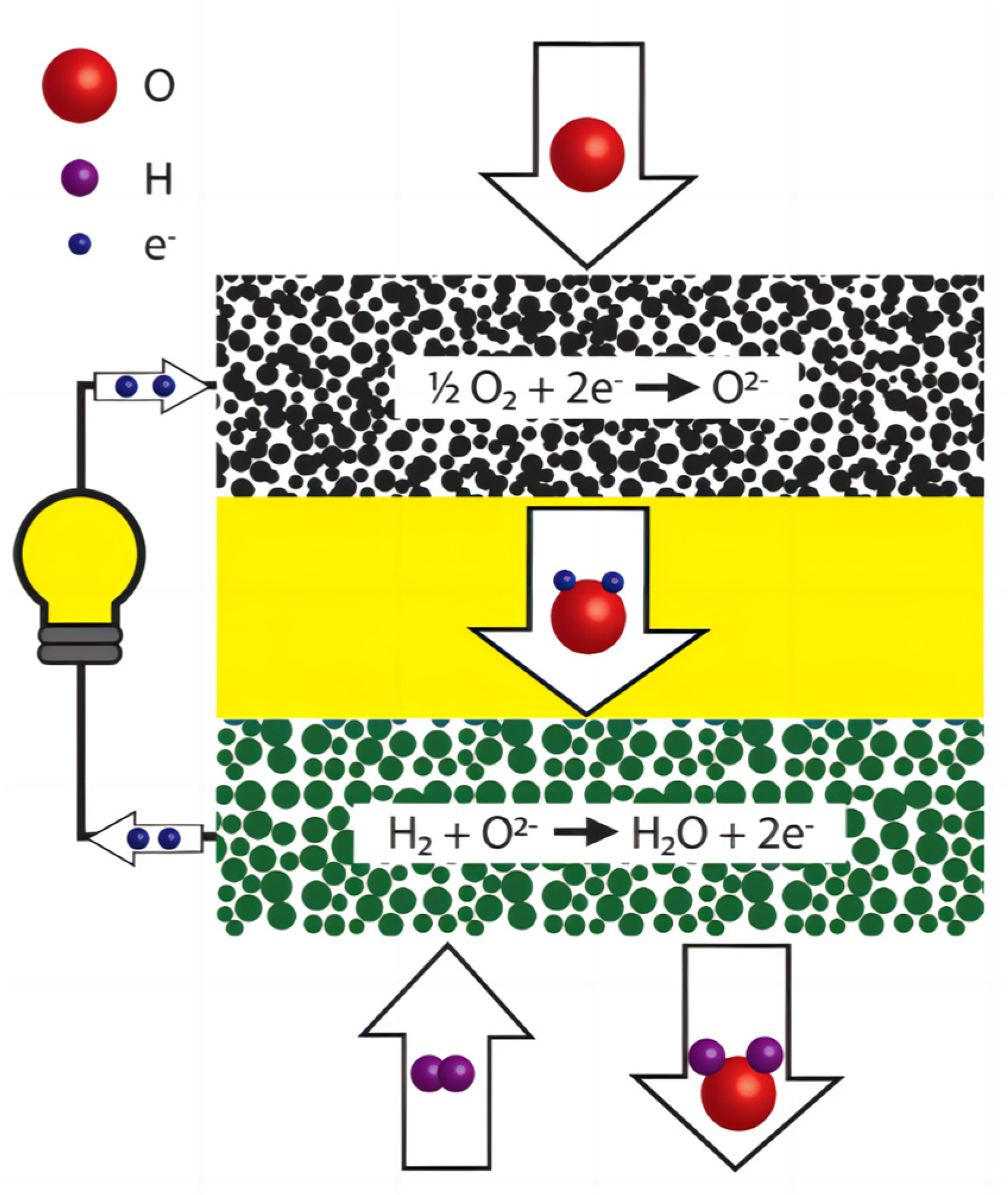
The main components of the SOFC structure include a porous anode, dense electrolyte, porous cathode, and connectors [34]. The cathode and anode are the primary components for gas-catalyzed reactions and electron transfer. The dense electrolyte layer serves as an electronic insulator, preventing cathode–anode contact, internal short circuits, and isolating the fuel gas from the oxidizing gas, while also conducting oxygen ions or protons. Depending on the type of ions conducted by the electrolyte, SOFCs can be categorized into oxygen ionic and protonic SOFCs [35]. For an oxygen ionic SOFC, Figure 1 illustrates its simple working principle. Fuel gas is introduced from the anode side of a SOFC system. The fuel gas undergoes an oxidation reaction at high temperatures to release electrons. These electrons then pass through an outer circuit and reach the cathode, providing power to an external circuit load. The electrons flowing to the cathode undergo a reduction reaction with the incoming oxygen, producing oxygen ions. Subsequently, the oxygen ions are transported to the anode through the electrolyte of the oxygen ion conductor, where they react with the fuel to release electrons.
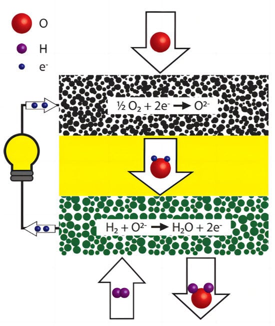
Figure 1.
Components and working principles of an oxygen ionic SOFC. Layers from up to down: cathode, electrolyte, anode. Reprinted with permission from Ref. [36]. Copyright 2018 WIREs Energy and Environment.
2.2. Protonic Ceramic Fuel Cell
2.2.1. Introduction to Proton Ceramic Fuel Cell
The Protonic ceramic fuel cell is currently the focus of intense development and research. It is a promising electrochemical device for the efficient and clean conversion of hydrogen and hydrocarbon fuels into electrical energy [37]. It combines the thermal and kinetic benefits of solid oxide fuel cells with the inherent advantages of proton exchange membrane fuel cells (PEMFCs) and proton conductivity of phosphoric acid fuel cells (PAFCs). PCFCs are among the most promising energy conversion devices due to their low cost and good durability [38]. They can be operated at much lower temperatures (400–650 °C) compared to their oxide-ion-conducting counterparts, which require temperatures above 700 °C. Lower operating temperatures offer several cost-effective benefits, including shorter start-up times, reduced energy input required to heat the cell to operating temperature, and extended material lifetimes [39,40]. In recent years, research on PCFCs has garnered increasing attention, and the research fervor continues to grow.
2.2.2. Working Principles of Protonic Ceramic Fuel Cells
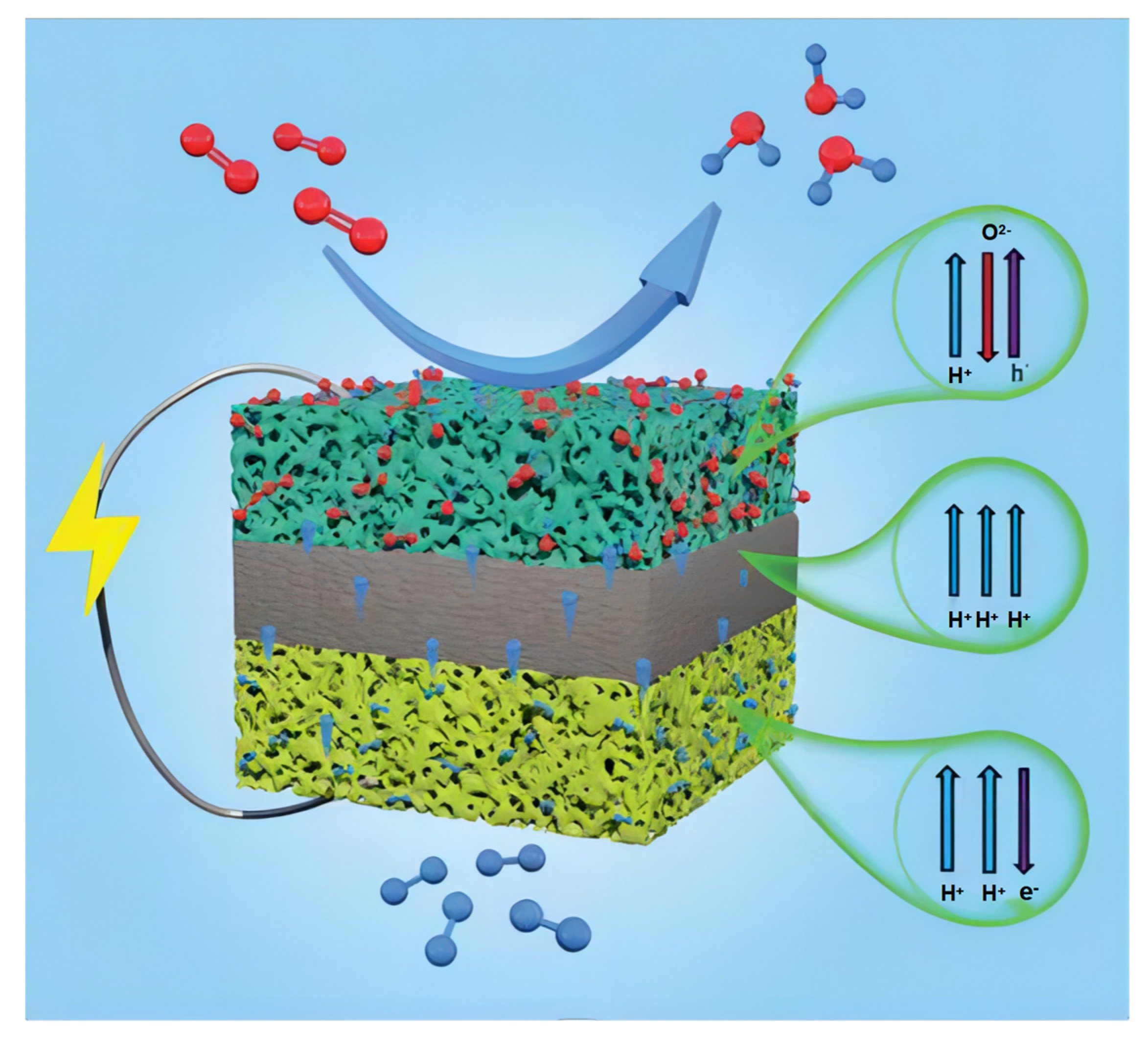
There are differences between PCFCs and conventional SOFCs, which are based on oxygen ion conduction. The fuel (H2, CH4, NH3, etc.) supplied at the anode side is catalytically dissociated into protons and electrons. Afterward, heat-activated protons diffuse through the electrolyte to the cathode side, while electrons are transmitted through an external circuit to power external devices. On the cathode side, the adsorbed oxygen gains electrons and is reduced to oxygen ions, which then react with protons delivered from the anode to form water [41].
In the case of H2 fuel, the electrochemical reaction that takes place inside the anode is simply represented by the following steps:
Anodic reaction: 2H2 → 4H+ + 4e−;
Cathodic reaction: 4H+ + O2 + 4 e− → 2H2O;
Total reaction: 2H2 + O2 → 2H2O.
The PCFC produces water at the cathode rather than the anode. This approach avoids fuel dilution, enhances fuel utilization, and improves overall system efficiency. Schematic representation of a PCFC structure is shown in the Figure 2. Protonic ceramic fuel cells can conduct protons through their lattice with low activation energies, resulting in higher ionic conductivities than SOFCs; thus, they can be operated at lower temperatures [42].
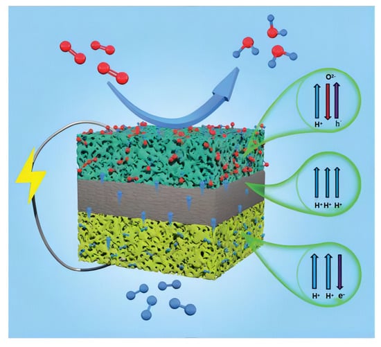
Figure 2.
Schematic representation of a PCFC structure. Reprinted with permission from Ref. [43]. Copyright 2022 Royal Society of Chemistry.
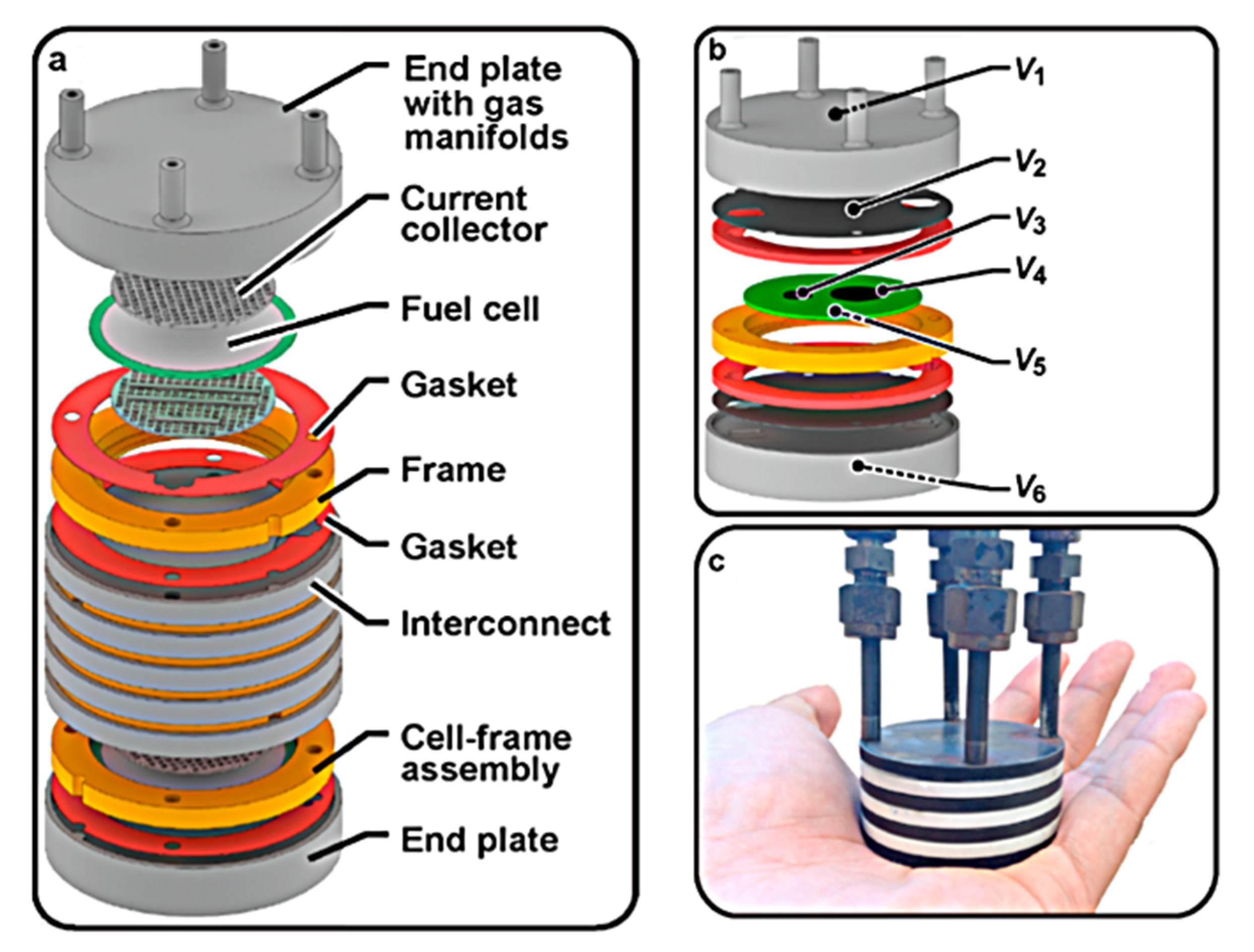
The stack schematic is shown in Figure 3 and was originally intended for use in a 50 W portable PCFC military application. The design is centered on three repetitive components: a protonic ceramic membrane electrode assembly (MEA), a composite ceramic frame combined with a MEA, and a metal interconnect/bipolar plate that conducts electricity between adjacent cells [44].
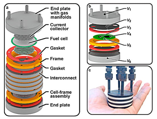
Figure 3.
Proton-conducting ceramic fuel cell stack: (a) schematic; (b) unit-cell stack with thin metallic interconnects and internal voltage taps at key interfaces. Note that V5 is connected to the surface of the cermet anode support, while V6 is connected to the outside of the anode endplate. (c) Photo of three-cell stack. Reprinted with permission from Ref. [44]. Copyright 2021 Elsevier B.V.
3. Manufacturing Method of PCFCs
There are various methods used for manufacturing PCFCs, including solid-state reactive sintering (SSRS), spark plasma sintering (SPS), microwave sintering, tape casting, and 3D printing. One of the primary challenges in the fabrication of protonic ceramic-based energy conversion devices is the necessity of high temperatures (1600–1700 °C) and long firing time (>10 h) Additionally, the refractory nature of the ceramics makes them well-suited for use as structural materials. However, it is sometimes seen as a hindrance when they are used as a functional material, which makes the sustainable and clean manufacturing of proton ceramic devices impractical [45]. Here, we offer a comprehensive introduction to sustainable and clean manufacturing techniques for proton ceramic energy devices, along with conventional traditional methods, and briefly outline some alternative approaches.
3.1. Conventional Processing Technology for PCFC
3.1.1. Solid-State Reactive Sintering
SSRS is a commonly used method for preparing powder materials. Specifically, solid-phase reaction refers to a chemical reaction involving two or more solid materials and generating a new compound. This method combines solid-phase reaction and sintering in a single step [46]. This method greatly simplifies the production of protonic-conducting ceramics by integrating phase formation, densification, and grain growth into a single high-temperature sintering step [47]. This reaction occurs through solid surface contact, so the reaction efficiency is generally improved by grinding the powder into small particles, thereby increasing the contact area between the particles. Solid-state reactive sintering is the process of sintering a pressed mixture at a temperature below the melting point, based on solid-phase reaction. During sintering, the air between the powder particles is expelled, and particle aggregation, crystallization, and densification occur among the reactants [48]. Therefore, solid-state reaction sintering is one cost-effective method for synthesizing and manufacturing [19,49]. The experiment by Zhao et al. [50] also indicates that the one-pot SSRS method can be used to prepare ideal components for proton ceramic electrochemical devices. Tong et al. [51] report that large particle size BaZr0.8Y0.2O3−δ (BZY20) can be prepared at a low cost using simple SSRS methods. In the SSRS process, the sintering time and the sintering temperature can be significantly reduced by adding proper sintering additives.
3.1.2. Spark Plasma Sintering
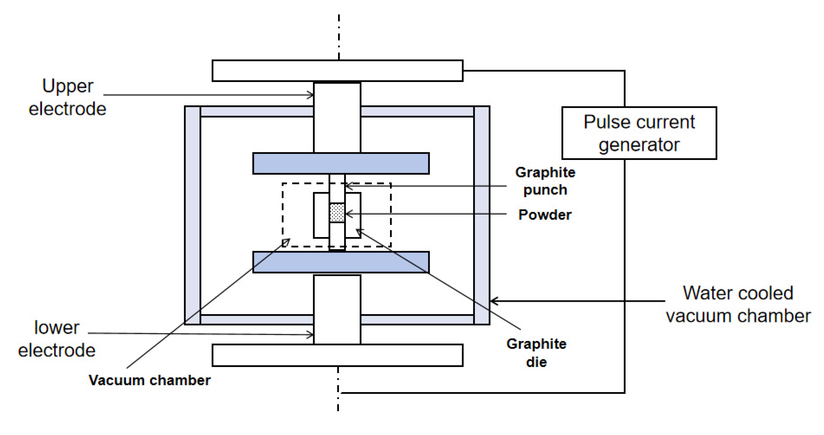
Spark plasma sintering (SPS) is an innovative sintering technology that utilizes high-energy, low-voltage pulsed current to instantly generate a discharge plasma in the local area between the particles. SPS is a promising method for obtaining solid electrolytes for PCFCs at lower temperatures (by 400–500 °C), compared to traditionally used temperature conditions [52]. For the sintering mechanism of SPS, it is generally believed that in addition to the Joule heat caused by hot-press sintering and the plastic deformation caused by pressure promoting the sintering process, the SPS process also generates a DC pulse voltage between powder particles. At the same time, it effectively utilizes the surface activation and self-heating effects generated by the discharge between powder particles. Therefore, a phenomenon unique to the SPS process that is beneficial for sintering has emerged [53]. SPS rapidly heats the materials under uniaxial pressure to produce high-density ceramics. The ability to apply very high heating and cooling rates, short residence times, and sintering at relatively low temperatures limits grain growth during densification [54]. SPS can be categorized as a low-temperature sintering technique, and the principle of discharge plasma sintering is shown in Figure 4 [55].
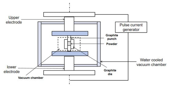
Figure 4.
Schematic diagram of discharge plasma sintering.
3.1.3. Microwave Sintering
Microwave sintering is the utilization of microwaves, which have a special band with the basic fine structure of the material coupled to generate heat. This method exploits the material’s dielectric loss, causing an overall heating of the material to the sintering temperature and realizing densification. It transfers heat directly to the material through the coupling of electromagnetic waves, thus realizing volumetric heating in the microwave field, which improves the heating efficiency, and also has the feasibility of being used in the fabrication of lumped components compared with discharge plasma sintering [56]. It is characterized by fast heating speed, high energy utilization, high heating efficiency, safety, hygiene without pollution, and the ability to improve the uniformity and yield of the product, as well as improve the microstructure and property of the sintered material. Microwave sintering is widely used in the ceramic industry due to its self-heating nature, which enables fast and efficient sintering [57]. Due to the use of lower temperatures in microwave sintering, less grain growth or coarsening can be seen without the use of any commercial grain growth inhibitors, and due to the advantages of microwave sintering, it has become possible to fabricate hard materials at lower than usual temperatures [58].
3.1.4. Hot-Press Sintering
Hot-press sintering (HPS) is a useful method to synthesize low-temperature densification ceramics [59,60,61]. It is a sintering technique in which the green body is heated and pressurized at the same time to promote sintering, thus eliminating the pores in the ceramic and realizing the high densification of the ceramic; an example of preparing SiC ceramics using hot-press sintering is shown in Figure 5. Hot-press sintering can only be used to prepare ceramic parts with simple shapes, but the ceramics have a high density and excellent high-temperature mechanical properties, which have great application prospects [55].

Figure 5.
Process flow of SiC ceramics prepared by hot-press sintering.
3.2. Printing Technology for PCFC
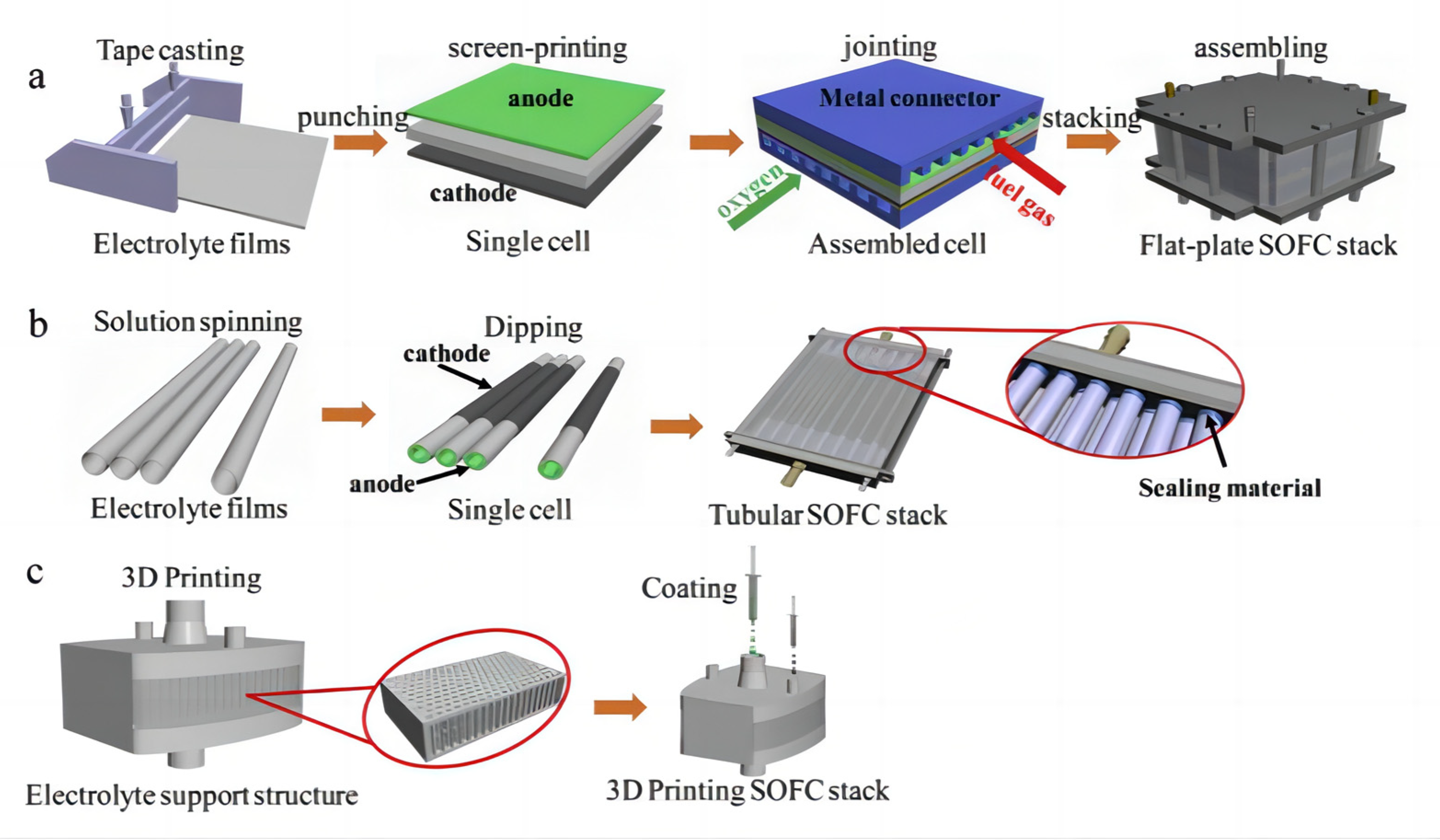
In recent years, with the rapid development of 3D printing technology, more and more manufacturing industries are beginning to apply it to the production process. 3D printing technology is a kind of processing technology to make three-dimensional objects by stacking materials layer by layer. Its working principle is mainly applied through computer-aided design software to transform the three-dimensional model into a digital model, and then through the 3D printer control system to divide the digital model into a series of two-dimensional slices, and finally through the layer-by-layer stacking of materials using layer-by-layer printing; as a result, two-dimensional slices are gradually stacked into a three-dimensional object [62]. 3D printing technology can greatly shorten the product manufacturing cycle, and improve production efficiency and flexibility, to meet the needs of personalized and small batch production, and at the same time can achieve a very complex and detailed product design, thus bringing significant improvements in the performance and quality of products. Compared with traditional manufacturing methods, 3D printing technology has the advantages of low manufacturing costs, high production efficiency, and large degree of freedom of design. Its unique advantages are especially reflected in the manufacturing of complex parts; thus, some people even call it “the most iconic production tool of the third industrial revolution” [63]. Tape casting, punching, screen-printing, laminating, and stacking are common procedures to fabricate planar configuration SOFC stacks, as shown in Figure 6a. The tubular structure SOFC stacks first prepare each single cell individually and then assemble all the cells into a stack, as shown in Figure 6b. 3D printing technology can produce SOFC battery stacks in one step, as shown in Figure 6c [64,65,66,67,68,69].
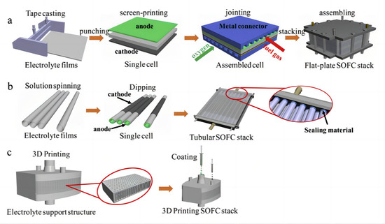
Figure 6.
SOFC stack by traditional manufacturing processes (a,b) and 3D printing technique (c). Reprinted with permission from Ref. [69]. Copyright 2019 Elsevier B.V.
The main 3D printing technologies include laser-based printing technology and non-laser-based printing technology. Laser-based printing technologies include light-curing printing, selective laser sintering (SLS), and laser 3D printing. In addition, light-curing printing includes stereolithography apparatus (SLA) and digital light processing (DLP). Non-laser-based printing technology includes inkjet printing and extrusion 3D printing. Extrusion 3D printing is also known as the extrusion free forming (EFF), layered extrusion molding, or direct ink writing (DIW) of paste materials. Comparison of 3D printing technology is shown in the Table 1.

Table 1.
Comparison of 3D printing technology.
3.2.1. Laser-Based Processes
Light-curing printing belongs to a type of rapid prototyping technology, which can prepare structures with complex, small, and hollow structural items. At present, the light-curing printing can be divided into stereolithography apparatus (SLA) and digital light processing (DLP) according to the different molding methods.
SLA is one of the more popular 3D printing technologies, which generally uses a ceramic paste of photosensitive resin and micro- and nano-ceramic powders mixed in a certain ratio. Then, a specific wavelength of ultraviolet light is used to solidify the paste from point to line, and from line to surface scanning. The paste in the light irradiation occurs after the curing bond. The light-curing printing process involves different methods, either from bottom to top or from top to bottom. Whenever the curing of the paste is completed, the printing platform is raised or lowered to a certain height according to the thickness of the layer, and the above operation is repeated until the complex structures of the ceramic parts are fully formed. Due to the particularly fine beam size used in SLA, the technology can achieve micron-level high-precision ceramic parts manufacturing. The formed blank has a very high density, effectively improving the mechanical properties of ceramic parts. This method is suitable for most ceramic powders, and has high versatility and uncomplicated processes, leading to a wide range of applications [63]. Stereolithography apparatus creates 3D objects by selectively curing liquid resins via a photopolymerization reaction. Light-curing rapid prototyping technology has attracted much attention due to its ability to produce high-precision objects and a wide variety of materials [70]. Griffith et al. [71] prepared SiO2, Al2O3, and Si3N4 powders with UV-curable solutions to form suspensions with a solid content ranging from 40% to 55%, and used them for ceramic body molding. This is the first report that stereolithography has been combined with the preparation of complex ceramic components.
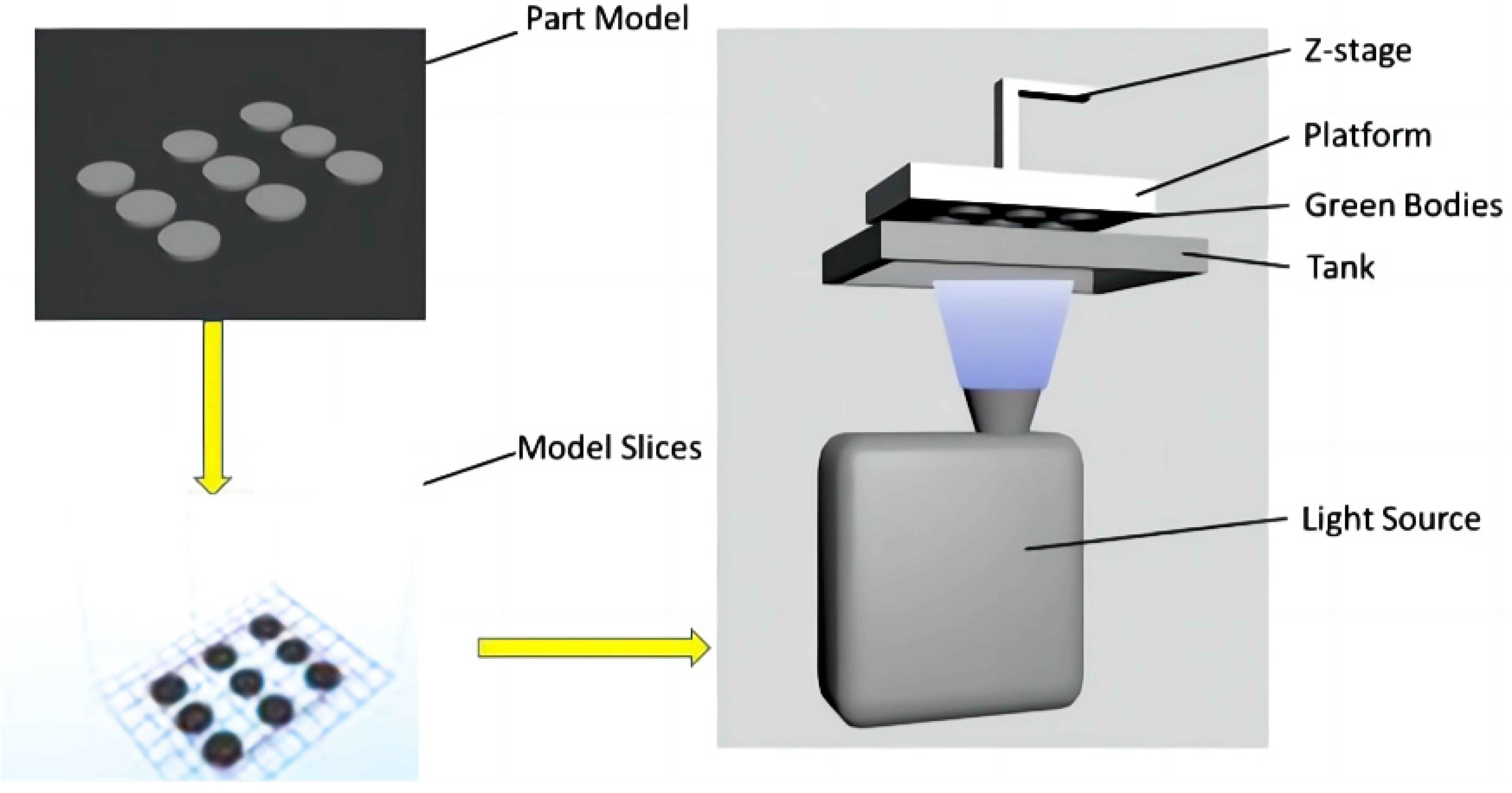
The DLP process is the evolution of the SLA printing process. They have similar printing processes and mechanisms, with the main difference being that the light sources used in DLP are digital and directly used for surface molding, which greatly improves printing efficiency, as shown on Figure 7 [72]. In recent years, DLP rapid prototyping has been widely used in the preparation of structural ceramics such as SiO2, Al2O3, and ZrO2 [73,74,75,76,77,78], in which the high hardness, high strength and mechanical properties are focused [69,73,79,80]. Wei et al. [69] looked at the fabrication of a dense 8YSZ electrolyte in a batch for SOFCs using the digital light stereolithography-based 3D printing technique. The SOFCs with the structure of Ag-GDC|YSZ|Ag-GDC showed good performance. They achieved an OCV of 1.04 V, and a maximum power density of 176 mW cm−2 with a hydrogen flow rate of 40 mL min−1 at 850 °C.
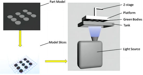
Figure 7.
The working principles of digital light stereolithography. Adapted with permission from Ref. [69]. Copyright 2019 Elsevier B.V.
Zhang et al. [81] successfully fabricated fully dense cube-shaped 8YSZ monoliths of tube bundles using digital light stereolithography 3D printing technology. The successful fabrication of complex-shaped 8YSZ monoliths via digital light stereolithography 3D printing provides a good example of how the 3D printing method can be applied to the energy field.
Mu et al. [82] developed a new laser 3D printing (L3DP) method by integrating 3D printing and laser processing. The characteristics of laser 3D printing are the use of commercial raw materials, a small amount of binder, and the use of a CO2 laser for rapid in situ drying [83]. The in situ 3D printing laser sintering technique combines digital micro-extrusion-based 3D printing with precise and rapid laser processing, which includes sintering, drying, cutting, and polishing. The L3DP method enables the fabrication of protonic ceramic (PC) components into different shapes, including cylinders, cones, straight or leaf-like tubes with sealed ends, microchannel membranes, and half-cells for assembling PC energy devices. This L3DP technology not only demonstrates the potential to put PCs into practical use, but also enables the rapid direct digital fabrication of ceramic-based devices [84,85,86]. By integrating 3D printing and laser processing (e.g., rapid drying, fast sintering, precise polishing, and accurate cutting), it enables the cost-effective material preparation and efficient attainment of well-defined shape and dimension-controlled uniform microstructures in porous anode supports, dense electrolytes, and porous cathodes [83].
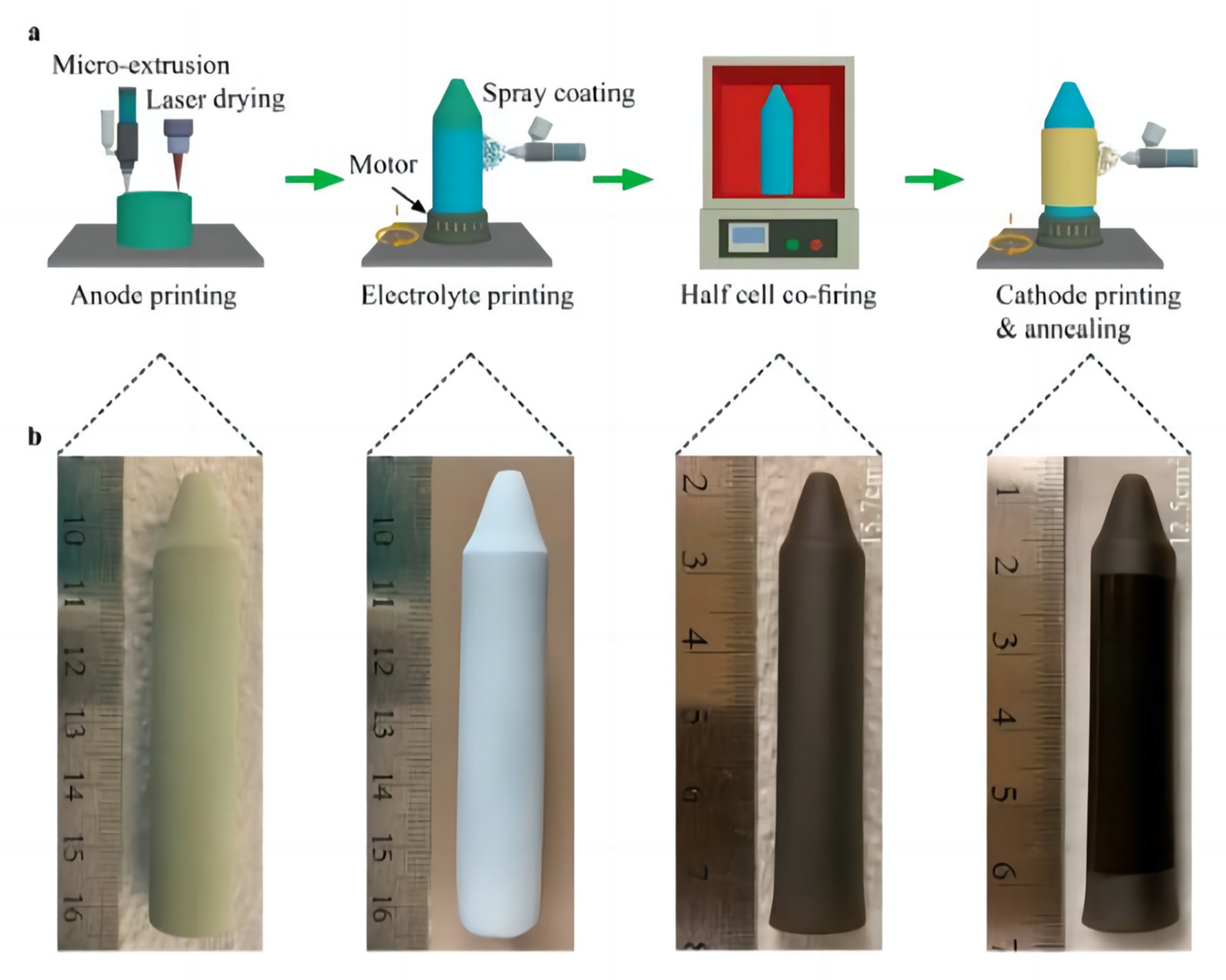
Zou et al. [83] used the L3DP to prepare a scalable tubular PCFC. The preparation process is simple and fast. This study suggested that the L3DP technique can manufacture PCFCs with high-power output and long life spans, ushering in new possibilities for commercializing scalable tubular PCFCs. Figure 8 shows the process of manufacturing a complete tubular PCFC using L3DP. Figure 8b shows a large uniform green anode tube with an outer diameter of approximately 13.5 mm and a height of approximately 73 mm, with a tapered end.
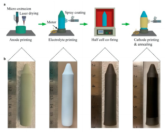
Figure 8.
Schematic illustration of the manufacturing of a single tubular PCFC by 3DP. (a) Schematic of the manufacturing process. (b) Photographs of the tubular PCFC at different manufacturing steps. Reprinted with permission from Ref. [83]. Copyright 2023 American Chemical Society.
Selective laser sintering (SLS) technology primarily utilizes a laser as the heat source. The ceramic powder is melted, bonded, and sintered under the laser irradiation to realize the ceramic powder melting, bonding, and sintering, layer by layer, to achieve three-dimensional solid molding manufacturing. SLS equipment mainly comprises a laser source, scanner, preheating device, control system, and other components. The process of this forming technology is as follows: first, a layer of heat-sensitive ceramic powder is spread on the forming platform. Then, the preheating device is heated to a temperature below the melting point of the powder. Next, the computer transmits the data of the CAD solid model to the control system. The control system then directs the laser to perform selective sintering based on the cross-section information of the model. Finally, the cured ceramic powder is stacked layer by layer to form the desired solid part by stacking one layer after another [87]. There are two types of SLS processes: indirect selective laser sintering (iSLS) [88] and selective laser melting (SLM) [89], depending on whether a binder is used during manufacturing. The main advantage of selective laser sintering technology lies in the ability to print a variety of single materials and composite materials with complex structures, high precision, high strength, and good mechanical properties. However, there are some limitations, such as a relatively narrow range of material selection, particularly complex process, and high cost [63].
3.2.2. Non-Laser-Based Printing Technology
In the field of ceramics, inkjet printing is a common printing technology used in industrial production to date [72]. As a non-contact and maskless manufacturing method, inkjet printing technology is mainly used for manufacturing by precisely positioning the print head and controllably ejecting and depositing the ink containing the desired material in the form of fine ink droplets onto a pre-determined substrate surface. 3D printing manufacturing can be achieved by repeated deposition to achieve layer-by-layer cumulation. This technology has been used in the manufacturing of some precision ceramic parts [90], especially ceramics with thin layers. Inkjet printing has the advantages of low-cost, easy, fast, and precise manufacturing. Firstly, the printing can be carried out at atmospheric pressure, without the need for vacuum conditions, thus significantly saving production costs. Secondly, inkjet printing is environmentally friendly and avoids material waste. Finally, the technology exhibits a high degree of flexibility [91]. Some inkjet printing techniques also offer the precise regulation of droplet volume and droplet number delivered per unit area of substrate, thus precisely controlling the thickness of the layer. To date, inkjet printing technology is widely used in solar cells [92,93], sensors [94,95], electronic circuits [96,97], and other fields. It is expected to be one of the attractive alternative methods to fabricate thin layer components such as SOFC electrodes.
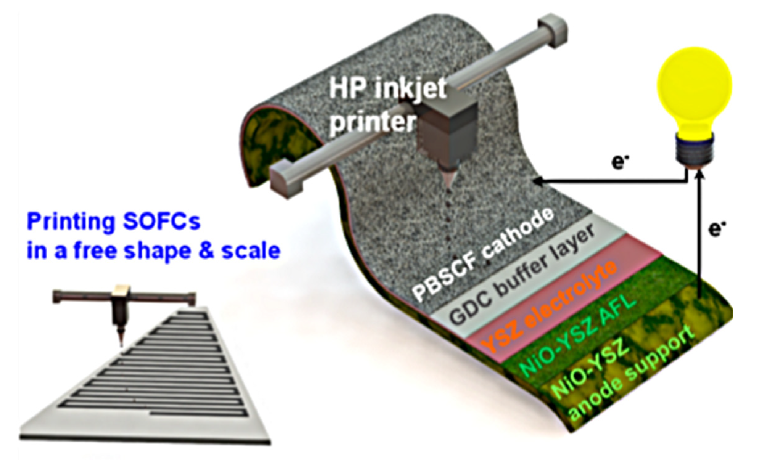
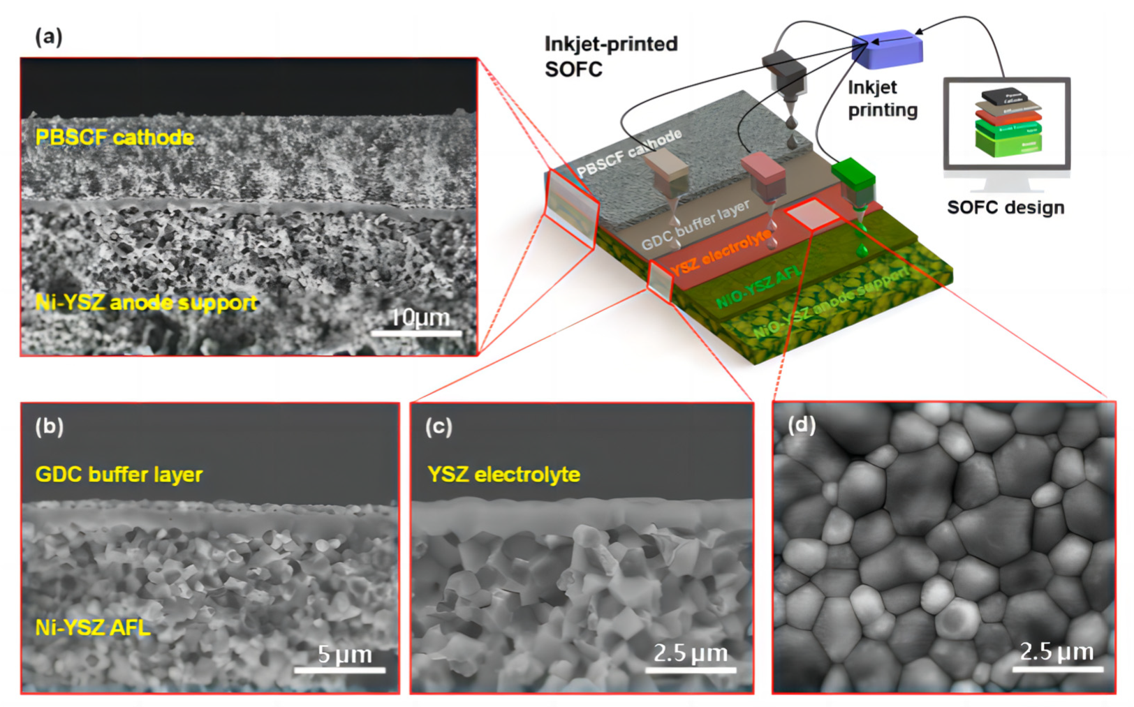
Inkjet printing technology prepares ceramic components, such as porous or dense electrodes and electrolyte thin layers, by employing ceramic nanopowder suspensions as inks to be sprayed drop by drop onto the surface of the substrate for spreading and fusing and stacking into a thin layer. Post-processing is also required, using drying and sintering methods. In recent years, there are also some scholars combining inkjet printing and other processes to prepare composite ceramic electrode components with good performance. One of the most important factors in realizing high-quality inkjet printing is the preparation of ceramic inks with matching printing requirements, which generally requires good stability, dispersion, and homogeneity. The composite also needs to be able to have a flat surface, uniform structure, and material distribution after post-treatment, using drying and sintering processes, in order to meet the requirements for SOFC usage [98]. Han et al. [99] proposed a method to manufacture an entire SOFC using a low-cost commercial inkjet printer, as shown in Figure 9.
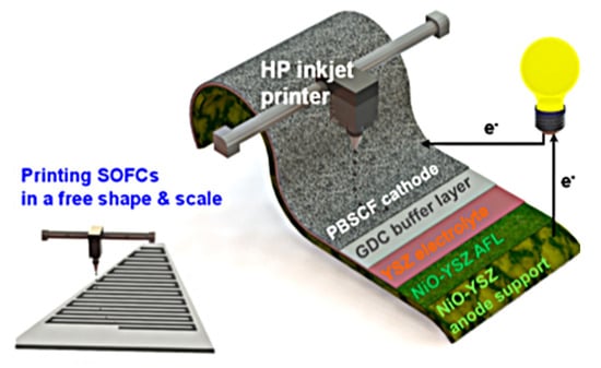
Figure 9.
Schematic diagram of the inkjet-printed SOFC composed of NiO−YSZ|YSZ|GDC|PBSCF. PBSCF represents PrBa0.5Sr0.5Co1.5Fe0.5O5+δ. Reprinted with permission from Ref. [99]. Copyright 2020 American Chemical Society.
Extrusion 3D printing is centered on the idea of paste extrusion molding, in which solids are formed from an extruded paste stacked on a printing platform, also known as the extrusion free forming (EFF), layered extrusion molding, or direct ink writing (DIW) of paste materials. Extrusion 3D printing methods can be considered as an extension of traditional inkjet printing techniques and can be used as a substrate-friendly method for printing unique microstructures for electrochemical energy storage devices [91]. Its advantages are that the process and equipment are simple and easy to implement; it does not require the high energy output consumption that laser printing requires, thus consuming less energy and lower costs. However, the problems, such as lower molding accuracy and a slurry that is not easy to be preserved, still need to be improved and solved [100].
3.3. Other Advanced Manufacturing Methods
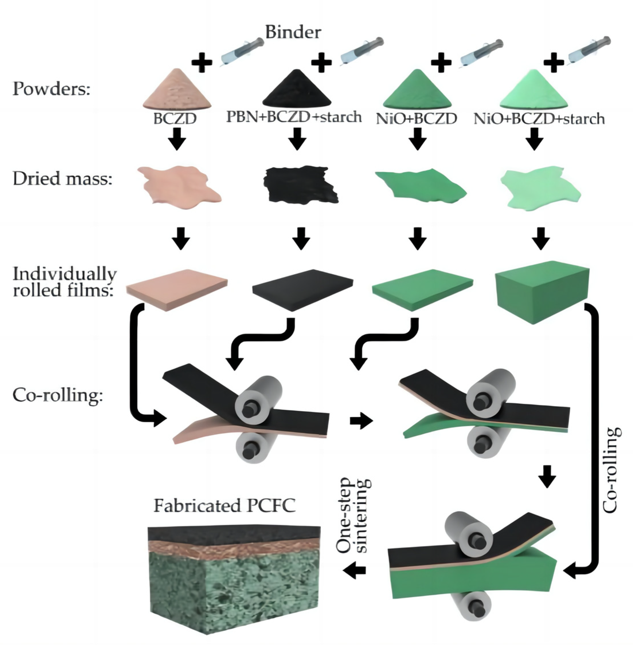
Artem Tarutin et al. [39] performed the one-step fabrication of protonic ceramic fuel cells using a convenient tape calendering method. The success of this fabrication approach is due to two main factors: the rational choice of chemically and mechanically compatible components, as well as the selection of a convenient preparation (tape calendering) method. Figure 10 shows the preparation process of fabricating PCFCs using this method. Firstly, four separate powders for the corresponding functional layers were prepared, and then a mixture of the corresponding powders and an organic binder was prepared. Then, the mixtures were dried overnight to evaporate and remove the solvent. The dried residues were rolled to fabricate the corresponding film layers with the required thicknesses, and finally, sintering was performed.
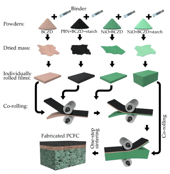
Figure 10.
Principal scheme of protonic ceramic fuel cells (PCFCs) fabricated by tape calendering method and one-step sintering. Reprinted from Ref. [39].
4. Research Progress in Technical Characterization Methods
4.1. Microstructure of PCFCs
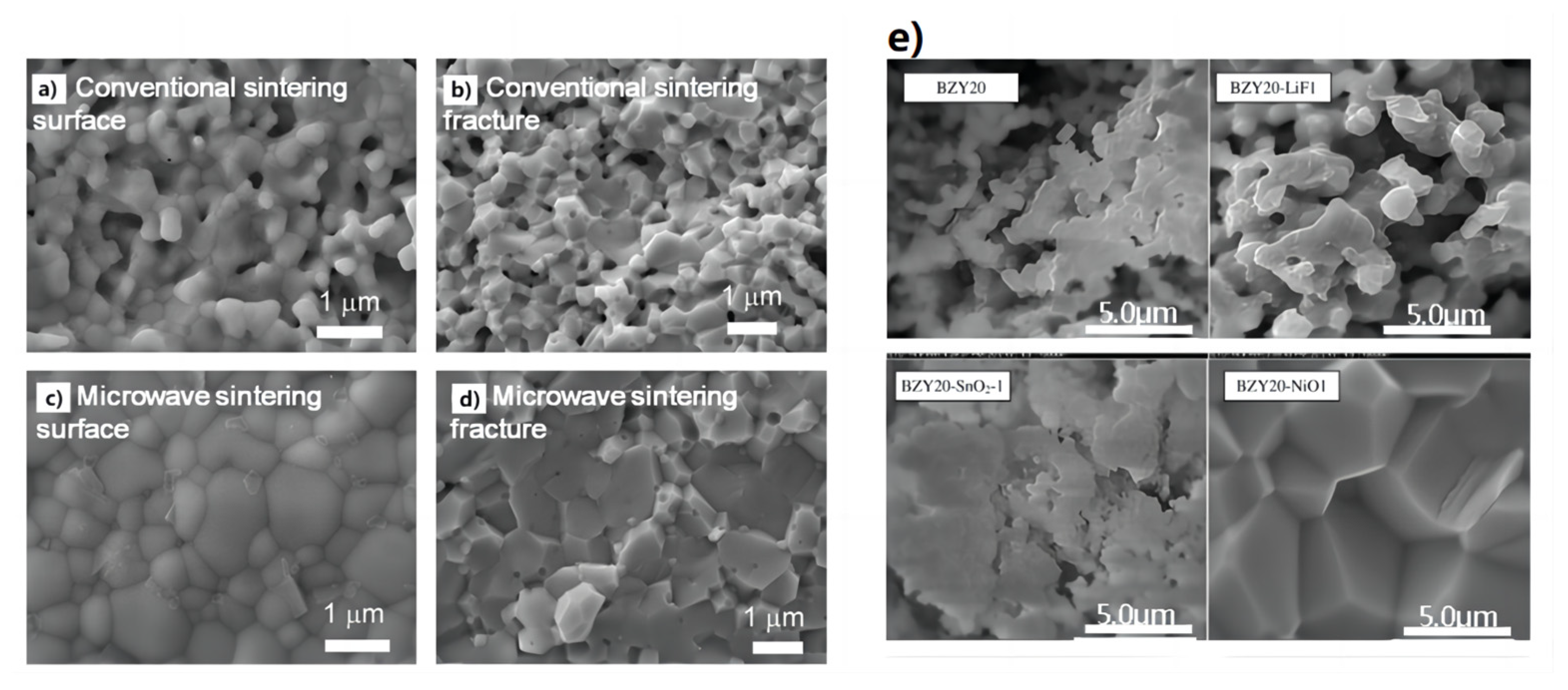
Xu et al. [101] prepared proton-conducting electrolyte membranes for solid oxide fuel cells using the microwave sintering strategy. The preparation of a dense proton-conducting BaCe0.7Zr0.1Y0.2O3−δ (BCZY) electrolyte membrane can be prepared at 1200 °C using the microwave sintering method. Figure 11a–d compares the BCZY electrolyte membranes sintered in an traditional electric furnace and microwave furnace. The presence of apparent pores were observed in the BCZY electrolyte membrane that was sintered using a traditional electric furnace. In contrast, the BCZY membrane sintered in the microwave furnace appears dense after sintering at the same temperature of 1200 °C. This suggests that microwave heating is advantageous for the formation of dense proton-conducting membranes and effectively reduces the densification temperature of BCZY electrolyte materials.
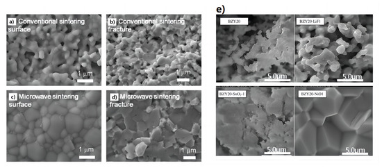
Figure 11.
Morphologies of (a,b) conventionally sintered and (c,d) microwave-sintered BCZY membranes after the thermal treatment at 1200 °C for 2 h. Adapted with permission from Ref. [101]. Copyright 2018 Elsevier B.V. (e) Sintering aid type effect on BZY20 pellet morphology (additive amount 1 wt.%, sintering temperature 1500 °C, sintering time 24 h). Adapted with permission from Ref. [51]. Copyright 2010 Elsevier B.V.
Tong et al. [51] used cost-effective precursors of BaCO3, ZrO2, and Y2O3 to prepare proton-conducting ceramic pellets of BaZr0.8Y0.2-O3−δ (BZY20). A range of sintering aids, including LiF, NiO, Al2O3, and SnO2, were used to help the densification of BZY20 membranes. This simple and cost-effective solid-state reactive sintering (SSRS) method involved only a single high-temperature sintering step. Figure 11e provides the effect of the sintering aid type on the BZY20 pellet morphology. The most dramatic changes were observed for the 1 wt.% NiO-modified BZY20 pellet, which exhibited a non-porous cross-section with equiaxed grains as large as 5 μm. Importantly, the large grain size and high density of this pellet should bode well for its protonic conductivity and use in applications related to functional protonic ceramics.
Han et al. [99] proposed a method for manufacturing an entire SOFC using a low-cost commercial inkjet printer. In Figure 12a–c, a fully dense YSZ electrolyte with a very small thickness of approximately 0.8 μm was successfully formed on the Ni-YSZ anode functional layer (AFL). The thin YSZ electrolyte formed after two printing scan cycles maintained its gastight and uniform microstructure even after the anode reduction process at 600 °C, following two printing scan cycles. As depicted in Figure 12d, the surface morphology of the YSZ electrolyte exhibited a tightly bound grain structure, clearly indicating that inkjet printing can be successfully used to form fully dense and extremely thin electrolytes at submicron levels.
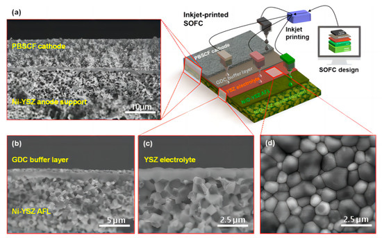
Figure 12.
Microstructures of the inkjet-printed SOFC composed of NiO−YSZ|YSZ|GDC|PBSCF. (a) Cross-sectional SEM image of the anode-supported SOFC and schematic of the inkjet printing (scale bar: 10 μm). (b) Cross-sectional SEM image of the SOFC with the approximately 0.5 μm thick GDC buffer layer (scale bar: 5 μm). (c) Cross-sectional and (d) surface SEM images of the SOFC with the approximately 0.8 μm thick YSZ electrolyte layer (scale bar: 2.5 μm). Reprinted with permission from Ref. [99]. Copyright 2020 American Chemical Society.
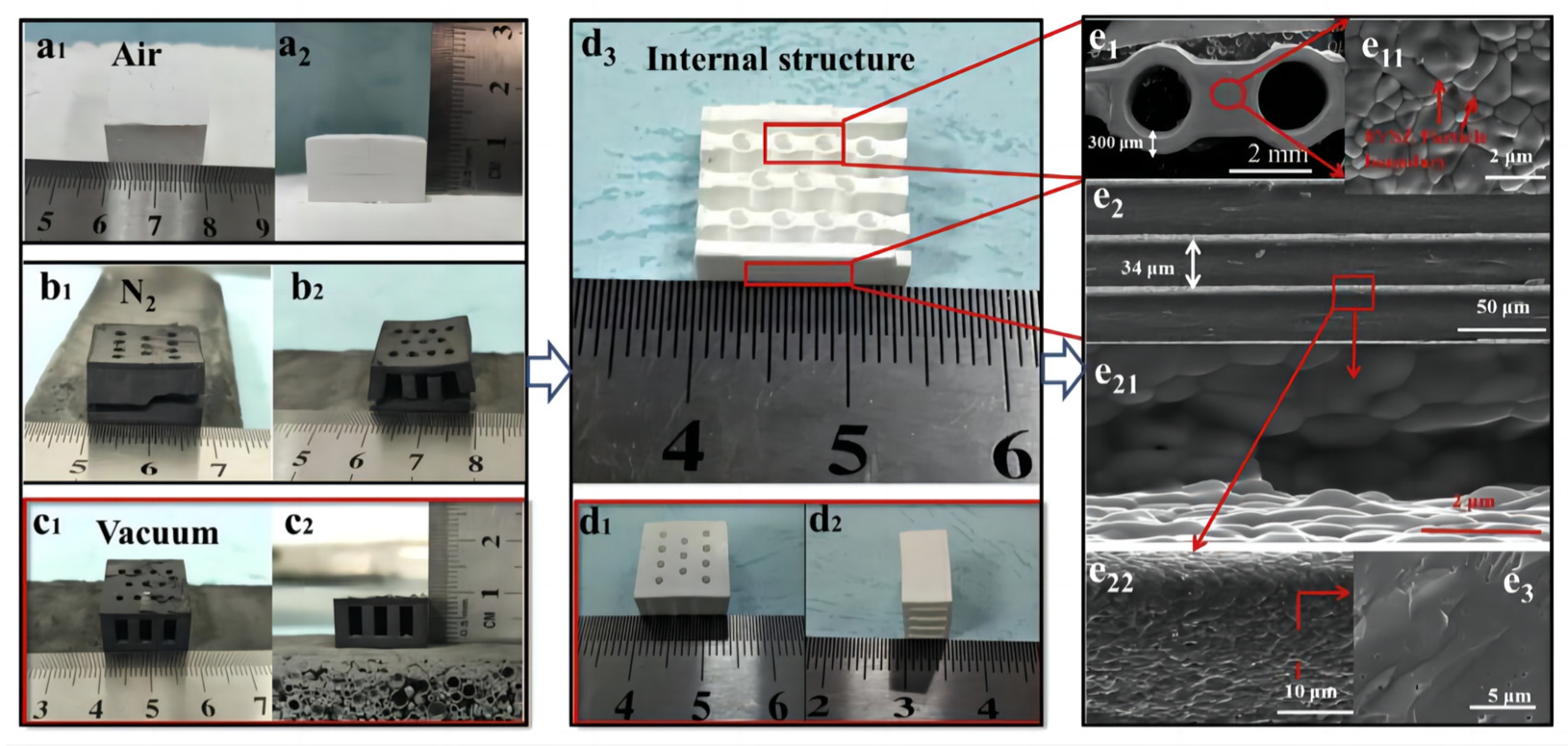
Zhang et al. [102] prepared 8 mol% yttria-stabilized zirconia (8YSZ) using DLP equipment. Figure 13a–c depict the green body prepared from the 30 vol% suspension via digital light 3D printing after degreasing under air, N2, and vacuum conditions. There are visible cracks in the green body degreased in air or N2, whereas there are no cracks in the green body degreased under vacuum conditions. The sintered compact forms are shown in Figure 13d. Figure 13(e11,e3) show SEM images of the surface and cross-section, respectively, of the sintered 8YSZ monoliths prepared from the 30 vol% suspension using digital light 3D printing. There are obvious cracks in the green body degreased in air or N2, while there are no cracks in the green body degreased under vacuum conditions. Figure 13(e11,e3) show SEM images of the surface and cross-section, respectively, of the sintered 8YSZ monoliths. Fully dense cube-shaped 8YSZ monoliths were successfully fabricated using digital light stereolithography 3D printing technology [102].
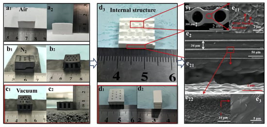
Figure 13.
Body after debinding in (a1,a2) air, (b1,b2) N2, and (c1,c2) under vacuum conditions; (d1–d3) body after sintering; (e1,e11,e2,e21,e22,e3) microstructure of 8YSZ monoliths after sintering. Reprinted with permission from Ref. [102]. Copyright 2020 Elsevier B.V.
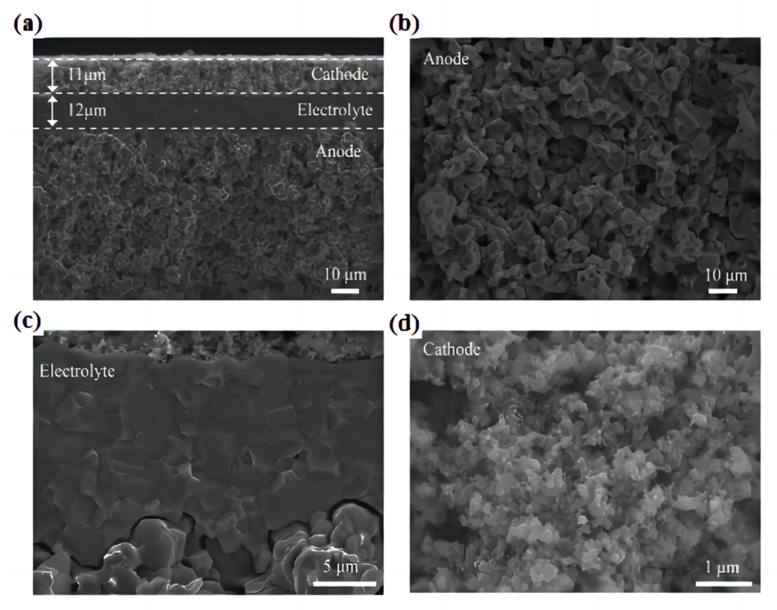
The single tube PCFC prepared using in situ 3D printing laser rapid reaction sintering technology displays a tubular BaCe0.2Zr0.7Y0.1O3−δ (BCZY27)-Ni comprising an anode support, a dense BCZY27 electrolyte film, and a porous cathode, BaCo0.4Fe0.4Zr0.1Y0.1O3−δ (BCFZY0.1). The well-controlled microstructure of the PCFC is shown in Figure 14a–d. The porous anode support exhibits a uniform and defect-free microstructure with a pore size of several micrometers. The electrolyte is uniform and dense, without visible pinholes or cracks, and adheres well to the porous electrode without exfoliation. The cathode has a fine porosity and nanoscale grains, which facilitate rapid gas transport and a large number of three-phase boundary positions, resulting in excellent electrochemical performance [83].
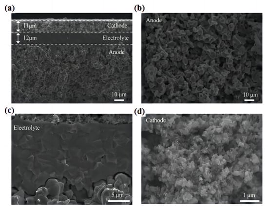
Figure 14.
Microstructure of the large-scale tubular PCFC with a 12.5 cm2 effective area after testing. (a) Cross-sectional SEM image of anode support (BCZY27−Ni)|electrolyte (BCZY27)|cathode (BCFZY0.1) sandwich structure. Enlarged cross-sectional SEM images of (b) the anode, (c) electrolyte/electrode interfaces, and (d) cathode. Reprinted with permission from Ref. [83]. Copyright 2023 American Chemical Society.
4.2. Crystal Structure and Performance
Ullah et al. [103] synthesized nanocomposite electrolytes using a microwave sintering technique instead of the conventional sintering method. Through an X-ray diffraction (XRD) analysis, it was indicated that the material was crystalline, exhibiting only one CeO2 phase. The crystallite sizes of MW-SDC (the microwave sintering technique was applied to synthesis of an SDC electrolyte called microwave-SDC) and CON-SDC (a conventional sintered electrolyte labelled CON-SDC) were calculated using Scherrer’s formula, and the relative densities of MW-SDC and CON-SDC were also determined to be 96% and 90%, respectively; the relative densities were also calculated from XRD data. Therefore, the major advantage of the microwave sintering is the ability to achieve highly dense materials [104].
Nikodemski et al. [47] elucidated the solid-state reactive sintering (SSRS) mechanism by systematically studying the effects of a series of metal oxide sintering additives on the phase formation and densification of proton-conducting ceramics. An XRD analysis indicated that the BCZY63 pellets sintered with the assistance of certain sintering additives showing, exhibiting an almost pure cubic perovskite phase of BCZY63 without any harmful second phase.
The Summary of XRD and SEM testing analysis is shown in the Table 2.

Table 2.
Summary of XRD and SEM testing analysis.
4.3. Electrochemical Properties
Ng et al. [108] investigated the effect of microwave sintering on the properties of 1 mol% ceria-doped scandia stabilized zirconia. This study has demonstrated the beneficial effect of microwave sintering in promoting the densification of 10Sc1CeSZ at lower temperatures and with a short sintering time. The sintered bodies show high ionic conductivity without sacrificing the cubic phase and mechanical properties for SOFC application.
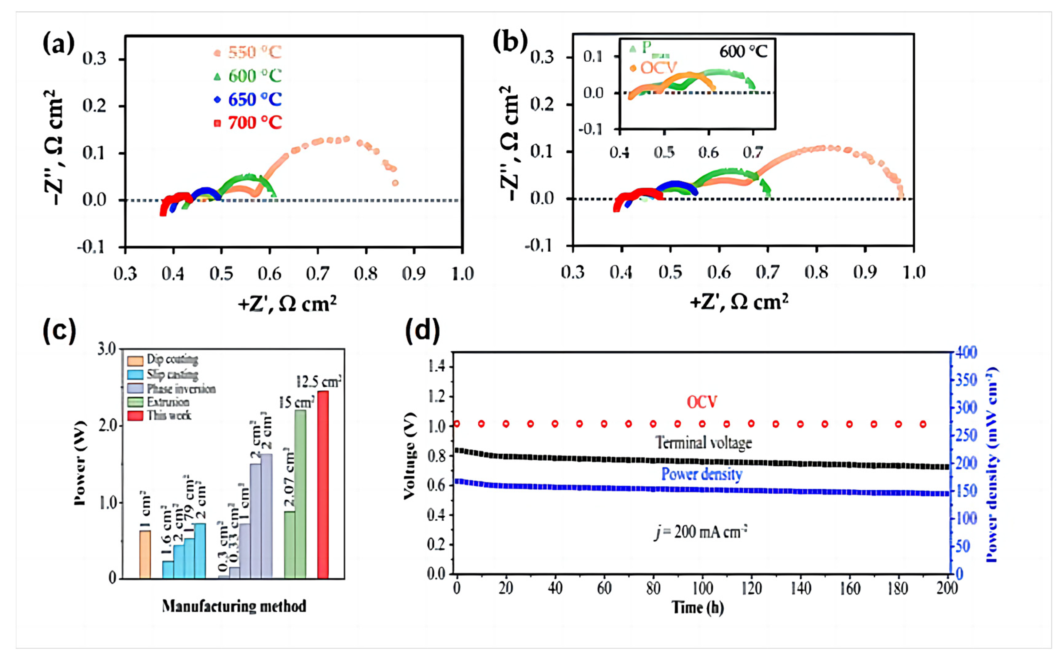
Artem Tarutiet al. [39] reported a one-step fabrication of PCFCs using a convenient tape calendering method. The electrochemical impedance spectroscopy (EIS) results presented in Figure 15a,b indicate that the spectra have different shapes depending on the measurement temperatures and/or cell bias. In detail, at least three parts (described by RQ elements, where R is the resistance, Q is the constant phase element) can be clearly distinguished at low temperatures; these merge to enable the detection of at least two (low- and high-frequency) processes at higher temperatures.
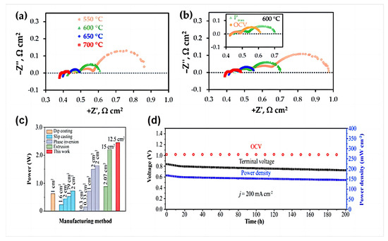
Figure 15.
Typical impedance spectra of the fabricated PCFC at different temperatures under conditions corresponding to open circuit voltage (OCV) (a) and Pmax (b). Reprinted from Ref. [39]. (c) Power output of single tube PCFCs prepared by different methods at 650 °C; (d) long-term stability of tube PCFCs at a constant current density of 200 mA cm−2 at 650 °C. Reprinted with permission from Ref. [83]. Copyright 2023 American Chemical Society.
Although the tubular PCFCs prepared by Zou et al. using L3DP have a larger effective area, they exhibit an area-specific resistance comparable to that of tubular PCFCs manufactured using state-of-the-art traditional methods. The prepared single tubular cell exhibits excellent electrochemical performance, with an effective area of 12.5 cm2 and a 2.45 W at 650 °C, as shown in Figure 15c. To evaluate the long-term stability of the manufactured tubular PCFCs, we tested a single battery for 200 h at a current of 200 mA cm−2 at 650 °C, as shown in Figure 15d. During the first 15 h of operation, the power density and cell terminal voltage slightly dropped (~4.3%) and in the remaining time thereafter, the degradation rate was 0.00039 V h−1, which can be negligible, confirming its long-term stability [83].
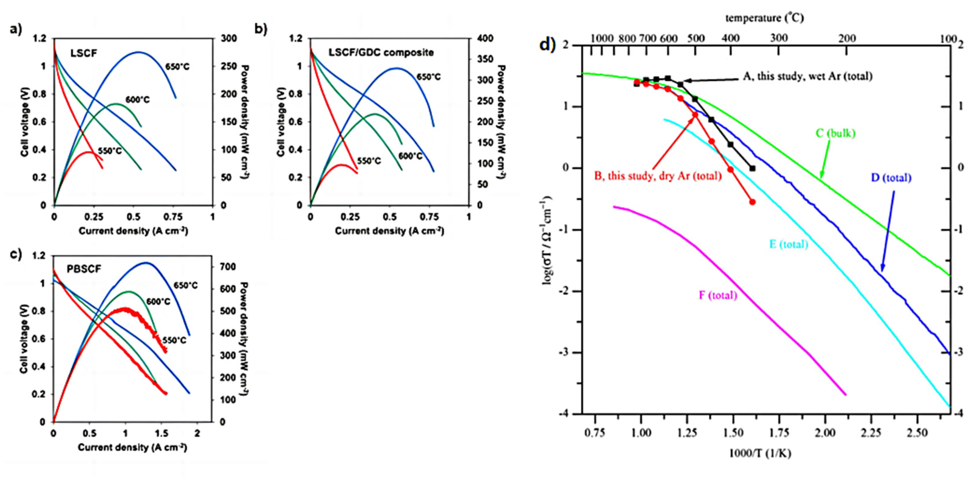
Kang et al. [109] successfully synthesized high performance components for solid oxide fuel cells and proton ceramic fuel cells by inkjet printing. Figure 16a–c shows that SOFCs with inkjet-printed LSCF and LSCF/GDC composite cathodes exhibit the maximum power of 95–274 mW cm−2 and 98–328 mW cm−2 at 550–650 °C, respectively. PCFCs with inkjet-printed PBSCF cathodes produced up to 430–720 mW cm−2 at 550–650 °C, respectively. This enhancement is due to the high ionic conductivity of proton-conducting materials compared to oxide-ion conductors. The results indicate that inkjet printing is effective for the manufacturing of PCFC.
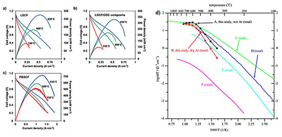
Figure 16.
(a,b) The I-V-P data measured from YSZ (10 µm-thick)-based SOFCs with LSCF (8 µm-thick) (left) and LSCF/GDC composite (8 µm-thick) cathodes at 550-650 °C. (c) The I-V-P data measured from BZCYYb (10 µm-thick)-based PCFCs with PBSCF (8 µm-thick) cathodes at 550–650 °C. Reprinted with permission from Ref. [109]. Copyright 2018 Elsevier B.V. (d) Arrhenius plots of total conductivity for BZY20 obtained using SSRS method with 2 wt.% NiO as sintering aid by sintering at 1500 °C for 24 h, and summary comparison with total or bulk conductivities recently reported for BZY20. Reprinted with permission from Ref. [51]. Copyright 2010 Elsevier B.V.
Tong et al. [51] evaluated the NiO-modified BZY 20 material using the DC four-point probe technique in both dry and wet argon gases, showing that the material has a fairly high total conductivity, as shown in Figure 16d.
The summary of electrochemical properties is shown in the Table 3, and comparison of electrical properties of devices with different preparation methods is shown in the Table 4.

Table 3.
Summary of electrochemical properties.

Table 4.
Comparison of electrical properties of devices with different preparation methods.
5. Future Directions
The current challenges faced by traditional solid oxide fuel cells have prompted researchers to consider proton-conducting solid oxide fuel cells as a feasible solution for achieving cleaner, more efficient, and more economical energy alternatives. The structure of the PCFC directly affects its performance, so the manufacturing technology is of vital significance to PCFC preparation methods. The future development direction of the PCFC preparation process will mainly focus on the following aspects:
- (1)
- At present, the problems existing in the preparation of proton conductor ceramic energy-integrated devices mainly stem from the characteristics of proton ceramics themselves, resulting in a large amount of energy consumption, high waste rate, low energy density, poor performance, and other problems in the actual preparation process. Therefore, it is necessary to continuously develop new preparation processes for ceramic energy equipment to achieve high-performance proton ceramic electrochemical devices.
- (2)
- Nowadays, although many new technologies have been used for the processing of PCFCs, most of them do not have the processing ability for complex and fine structures, which limits the development limit of equipment. Therefore, it is necessary to develop new technologies for ceramic energy equipment, achieve cost-effective requirements, and quickly prepare proton ceramic electrochemical devices with controllable structures, high energy density, and excellent performance, which become the key to the widespread application of such materials and equipment.
- (3)
- At present, most of the characterized superior properties of medium temperature proton ceramic energy devices come from small structures, which cannot meet the actual needs of large energy density devices. This is because the operating temperature range of the device imposes demanding requirements on the sealing, operation, and long-term stability of the cell stack. How to design and manufacture proton conductor ceramic devices with high integration, flexible and controllable structures, and meet different test requirements has become the direction of researchers’ efforts.
Author Contributions
Writing—original draft preparation, M.Y.; writing—review and editing, Z.L. and Q.F.; conceptualization, writing—review and editing, and supervision, P.Z., X.Z. and S.M. All authors have read and agreed to the published version of the manuscript.
Funding
This research was funded by the Youth Fund of the National Natural Science Foundation of China for the investigation of picosecond laser micro-machining-assisted in-situ 3D printing rapid laser reactive sintering for the fabrication of high performance protonic ceramic fuel cell stacks (52202271); the Provincial Doctoral Research Start-up Fund Project from Liaoning Provincial Department of Science and Technology for the study of fabrication technology on protonic ceramic-based fuel cell by laser 3D printing (2023-BS-144); the Liaoning Provincial Department of Education youth project for the study on the creation and functionalization of low temperature colored aeolian sand (JYTQN2023375); and the Innovative Research Fund of DICP for the preparation of BZY protonic-conducting electrolyte membranes at low temperature (DICP I202221).
Data Availability Statement
Data sharing is not applicable to this article.
Conflicts of Interest
There are no conflicts to declare.
References
- Cyril, P.H.; Saravanan, G. Development of advanced materials for cleaner energy generation through fuel cells. New J. Chem. 2020, 44, 19977–19995. [Google Scholar] [CrossRef]
- Kalinina, E.G.; Pikalova, E.Y. New trends in the development of electrophoretic deposition method in the solid oxide fuel cell technology: Theoretical approaches, experimental solutions and development prospects. Russ. Chem. Rev. 2019, 88, 1179–1219. [Google Scholar] [CrossRef]
- Ruiz-Morales, J.C.; Hernández-Rodríguez, E.M.; Acosta-Mora, P.; Méndez-Ramos, J.; Borges Chinea, E.; Esparza Ferrera, P.; Canales-Vázquez, J.; Núñez, P. Prospective use of the 3D printing technology for the microstructural engineering of Solid Oxide Fuel Cell components. Boletín De La Soc. Española De Cerámica Y Vidr. 2014, 53, 213–216. [Google Scholar] [CrossRef]
- Liu, J.; Sun, G. A survey of fuel cells. Physics 2004, 33, 79–84. [Google Scholar]
- Minh, N.Q.; Shirley Meng, Y. Future energy, fuel cells, and solid-oxide fuel-cell technology. MRS Bull. 2019, 44, 682–683. [Google Scholar] [CrossRef]
- Belhaj, I.; Faria, M.; Šljukić, B.; Geraldes, V.; Santos, D.M.F. Bipolar Membranes for Direct Borohydride Fuel Cells—A Review. Membranes 2023, 13, 730. [Google Scholar] [CrossRef]
- Ma, Y.; Huang, J.; He, B. Scalable fabrication process for new structure BaZr0.8Y0.2O3−δ-based protonic ceramic fuel cells. Ceram. Int. 2021, 47, 14680–14688. [Google Scholar] [CrossRef]
- Ivers-Tiffée, E.; Weber, A.; Herbstritt, D. Materials and technologies for SOFC-components. J. Eur. Ceram. Soc. 2001, 21, 1805–1811. [Google Scholar] [CrossRef]
- Priya, S.D.; Selvakumar, A.I.; Nesaraj, A.S. Overview on Ceramic and Nanostructured Materials for Solid Oxide Fuel Cells (SOFCs) Working at Different Temperatures. J. Electrochem. Sci. Technol. 2020, 11, 99–116. [Google Scholar] [CrossRef]
- Yang, G.; Su, C.; Shi, H.; Zhu, Y.; Song, Y.; Zhou, W.; Shao, Z. Toward reducing the operation temperature of solid oxide fuel cells: Our past 15 years of efforts in cathode development. Energy Fuels 2020, 34, 15169–15194. [Google Scholar] [CrossRef]
- Ali, A.; Irshad, M.; Siraj, K.; Raza, R.; Rafique, A.; Ullah, M.K.; Usman, A.; Tiwari, P.; Zhu, B.; Ali, A. A Brief Description of High Temperature Solid Oxide Fuel Cell’s Operation, Materials, Design, Fabrication Technologies and Performance. Appl. Sci. 2016, 6, 75. [Google Scholar]
- Kim, Y.S.; Chang, W.; Jeong, H.J.; Kim, K.H.; Park, H.S.; Shim, J.H. High performance of protonic ceramic fuel cells with 1-μm-thick electrolytes fabricated by inkjet printing. Addit. Manuf. 2023, 71, 103590. [Google Scholar] [CrossRef]
- Mu, S.; Zhao, Z.; Huang, H.; Lei, J.; Peng, F.; Xiao, H.; Brinkman, K.S.; Tong, J.J. Advanced Manufacturing of Intermediate-Temperature Protonic Ceramic Electrochemical Cells. Electrochem. Soc. Interface 2020, 29, 67. [Google Scholar] [CrossRef]
- Duan, C.; Tong, J.; Shang, M.; Nikodemski, S.; Sanders, M.; Ricote, S.; Almansoori, A.; O’Hayre, R. Readily processed protonic ceramic fuel cells with high performance at low temperatures. Science 2015, 349, 1321–1326. [Google Scholar] [CrossRef]
- Yang, L.; Wang, S.; Blinn, K.; Liu, M.; Liu, Z.; Cheng, Z.; Liu, M. Enhanced sulfur and coking tolerance of a mixed ion conductor for SOFCs: BaZr0.1Ce0.7Y0.2–xYbxO3−δ. Science 2009, 326, 126–129. [Google Scholar] [CrossRef]
- Choi, S.; Kucharczyk, C.J.; Liang, Y.; Zhang, X.; Takeuchi, I.; Ji, H.-I.; Haile, S.M. Exceptional power density and stability at intermediate temperatures in protonic ceramic fuel cells. Nat. Energy 2018, 3, 202–210. [Google Scholar] [CrossRef]
- An, H.; Lee, H.-W.; Kim, B.-K.; Son, J.-W.; Yoon, K.J.; Kim, H.; Shin, D.; Ji, H.-I.; Lee, J.-H. A 5 × 5 cm2 protonic ceramic fuel cell with a power density of 1.3 W cm−2 at 600 °C. Nat. Energy 2018, 3, 870–875. [Google Scholar] [CrossRef]
- Duan, C.; Kee, R.J.; Zhu, H.; Karakaya, C.; Chen, Y.; Ricote, S.; Jarry, A.; Crumlin, E.J.; Hook, D.; Braun, R. Highly durable, coking and sulfur tolerant, fuel-flexible protonic ceramic fuel cells. Nature 2018, 557, 217–222. [Google Scholar] [CrossRef]
- Bello, I.T.; Zhai, S.; He, Q.; Cheng, C.; Dai, Y.; Chen, B.; Zhang, Y.; Ni, M. Materials development and prospective for protonic ceramic fuel cells. Int. J. Energy Res. 2021, 46, 2212–2240. [Google Scholar] [CrossRef]
- Yu, J.; Ran, R.; Zhong, Y.; Zhou, W.; Ni, M.; Shao, Z. Advances in porous perovskites: Synthesis and electrocatalytic performance in fuel cells and metal–air batteries. Energy Environ. Mater. 2020, 3, 121–145. [Google Scholar] [CrossRef]
- Babilo, P.; Uda, T.; Haile, S.M. Processing of yttrium-doped barium zirconate for high proton conductivity. J. Mater. Res. 2007, 22, 1322–1330. [Google Scholar] [CrossRef]
- Kreuer, K.-D. Proton-conducting oxides. Annu. Rev. Mater. Res. 2003, 33, 333–359. [Google Scholar] [CrossRef]
- Mu, S.; Zhao, Z.; Lei, J.; Hong, Y.; Hong, T.; Jiang, D.; Song, Y.; Jackson, W.; Brinkman, K.S.; Peng, F. Engineering of microstructures of protonic ceramics by a novel rapid laser reactive sintering for ceramic energy conversion devices. Solid State Ion. 2018, 320, 369–377. [Google Scholar] [CrossRef]
- Bohn, H.G.; Schober, T.J. Electrical conductivity of the high-temperature proton conductor BaZr0.9Y0.1O2.95. J. Am. Ceram. Soc. 2000, 83, 768–772. [Google Scholar] [CrossRef]
- Iguchi, F.; Yamada, T.; Sata, N.; Tsurui, T.; Yugami, H. The influence of grain structures on the electrical conductivity of a BaZr0.95Y0.05O3 proton conductor. Solid State Ion. 2006, 177, 2381–2384. [Google Scholar] [CrossRef]
- Duval, S.; Holtappels, P.; Vogt, U.; Pomjakushina, E.; Conder, K.; Stimming, U.; Graule, T. Electrical conductivity of the proton conductor BaZr0.9Y0.1O3−δ obtained by high temperature annealing. Solid State Ion. 2007, 178, 1437–1441. [Google Scholar] [CrossRef]
- Tong, J.; Clark, D.; Bernau, L.; Sanders, M.; O’Hayre, R. Solid-state reactive sintering mechanism for large-grained yttrium-doped barium zirconate proton conducting ceramics. J. Mater. Chem. 2010, 20, 6333–6341. [Google Scholar] [CrossRef]
- Wang, Y.; Leung, D.Y.C.; Xuan, J.; Wang, H. A review on unitized regenerative fuel cell technologies, part B: Unitized regenerative alkaline fuel cell, solid oxide fuel cell, and microfluidic fuel cell. Renew. Sustain. Energy Rev. 2017, 75, 775–795. [Google Scholar] [CrossRef]
- Ma, Y.; He, B.; Wang, J.; Cheng, M.; Zhong, X.; Huang, J. Porous/dense bilayer BaZr0.8Y0.2O3−δ electrolyte matrix fabricated by tape casting combined with solid-state reactive sintering for protonic ceramic fuel cells. Int. J. Hydrogen Energy 2021, 46, 9918–9926. [Google Scholar] [CrossRef]
- Marrony, M.; Ancelin, M.; Lefevre, G.; Dailly, J. Elaboration of intermediate size planar proton conducting solid oxide cell by wet chemical routes: A way to industrialization. Solid State Ion. 2015, 275, 97–100. [Google Scholar] [CrossRef]
- Téllez Lozano, H.; Druce, J.; Cooper, S.J.; Kilner, J.A. Double perovskite cathodes for proton-conducting ceramic fuel cells: Are they triple mixed ionic electronic conductors? Sci. Technol. Adv. Mater. 2017, 18, 977–986. [Google Scholar] [CrossRef]
- Katz, E.; Bollella, P. Fuel Cells and Biofuel Cells: From Past to Perspectives. Isr. J. Chem. 2020, 61, 68–84. [Google Scholar] [CrossRef]
- Suzuki, M.; Sasaki, H.; Otoshi, S.; Kajimura, A.; Sugiura, N.; Ippommatsu, M. High performance solid oxide fuel cell cathode fabricated by electrochemical vapor deposition. J. Electrochem. Soc. 1994, 141, 1928. [Google Scholar] [CrossRef]
- Lu, J.B.; Zhang, Z.T.; Tang, Z.L. Review on the Development of Solid Oxide Fuel Cells. Rare Met. Mater. Eng. 2005, 34, 1177–1180. [Google Scholar]
- Ye, H. Preparation and Electrochemical Performance of Mixed-Conducting Cathode Materials for Protonic Ceramic Fuel Cell. Master’s Thesis, Guangdong University of Technology, Guangzhou, China, 2020. [Google Scholar]
- Jouttijärvi, S.; Asghar, M.I.; Lund, P.D. Microscopic techniques for analysis of ceramic fuel cells. WIREs Energy Environ. 2018, 7, e299. [Google Scholar] [CrossRef]
- Mather, G.C.; Muñoz-Gil, D.; Zamudio-García, J.; Porras-Vázquez, J.M.; Marrero-López, D.; Pérez-Coll, D. Perspectives on Cathodes for Protonic Ceramic Fuel Cells. Appl. Sci. 2021, 11, 5363. [Google Scholar] [CrossRef]
- Diao, Z.; Nishidate, K.; Imaizumi, T.; Kimura, Y.; Nakamura, T.; Mikami, Y.; Kuroha, T.; Yashiro, K.; Kawada, T.; Amezawa, K. Evaluation of Reaction Mechanism of PCFC Composite Cathodes by Utilizing Patterned Thin Film Model Electrodes. ECS Trans. 2021, 103, 1745–1751. [Google Scholar] [CrossRef]
- Tarutin, A.; Danilov, N.; Lyagaeva, J.; Medvedev, D. One-Step Fabrication of Protonic Ceramic Fuel Cells Using a Convenient Tape Calendering Method. Appl. Sci. 2020, 10, 2481. [Google Scholar] [CrossRef]
- Loureiro, F.J.A.; Ramasamy, D.; Graça, V.C.D.; Holz, L.I.V.; Mikhalev, S.M.; Fagg, D.P. Analysis of La4Ni3O10±δ-BaCe0.9Y0.1O3−δ Composite Cathodes for Proton Ceramic Fuel Cells. Appl. Sci. 2021, 11, 3407. [Google Scholar] [CrossRef]
- Guo, R. Design and Performance Modulation of Electrolyte Materials for low-Temperature Protonic Ceramic. Ph.D. Thesis, Jilin University, Changchun, China, 2023. [Google Scholar]
- Chien, A.C.; Chen, W.Y.; Zheng, M.S. Direct Conversion of Ammonia to Electricity on a PCFC and an SOFC. J. Electrochem. Soc. 2023, 170, 044505. [Google Scholar] [CrossRef]
- Cao, J.; Ji, Y.; Shao, Z. Perovskites for protonic ceramic fuel cells: A review. Energy Environ. Sci. 2022, 15, 2200–2232. [Google Scholar] [CrossRef]
- Le, L.Q.; Hernandez, C.H.; Rodriguez, M.H.; Zhu, L.; Duan, C.; Ding, H.; O’Hayre, R.P.; Sullivan, N.P. Proton-conducting ceramic fuel cells: Scale up and stack integration. J. Power Sources 2021, 482, 228868. [Google Scholar] [CrossRef]
- Mu, S.; Huang, H.; Ishii, A.; Hong, Y.; Santomauro, A.; Zhao, Z.; Zou, M.; Peng, F.; Brinkman, K.S.; Xiao, H.; et al. Rapid Laser Reactive Sintering for Sustainable and Clean Preparation of Protonic Ceramics. ACS Omega 2020, 5, 11637–11642. [Google Scholar] [CrossRef]
- Tong, J.; Clark, D.; Bernau, L.; Subramaniyan, A.; O’Hayre, R. Proton-conducting yttrium-doped barium cerate ceramics synthesized by a cost-effective solid-state reactive sintering method. Solid State Ion. 2010, 181, 1486–1498. [Google Scholar] [CrossRef]
- Nikodemski, S.; Tong, J.; O’Hayre, R. Solid-State Reactive Sintering Mechanism for Proton Conducting Ceramics. Solid State Ion. 2013, 253, 201–210. [Google Scholar] [CrossRef]
- Zhu, X.; Yang, W.J.G.C.; Technology, S. Mixed Conducting Ceramic Membranes; Springer: Berlin/Heidelberg, Germany, 2017. [Google Scholar] [CrossRef]
- Braun, R.J.; Dubois, A.; Ferguson, K.; Duan, C.; Karakaya, C.; Kee, R.J.; Zhu, H.; Sullivan, N.P.; Tang, E.; Pastula, M. Development of kW-scale protonic ceramic fuel cells and systems. ECS Trans. 2019, 91, 997. [Google Scholar] [CrossRef]
- Zhao, Z.; Zou, M.; Huang, H.; Wofford, H.; Tong, J. Stable perovskite-fluorite dual-phase composites synthesized by one-pot solid-state reactive sintering for protonic ceramic fuel cells. Ceram. Int. 2021, 47, 32856–32866. [Google Scholar] [CrossRef]
- Tong, J.; Clark, D.; Hoban, M.; O’Hayre, R. Cost-effective solid-state reactive sintering method for high conductivity proton conducting yttrium-doped barium zirconium ceramics. Solid State Ion. 2010, 181, 496–503. [Google Scholar] [CrossRef]
- Simonenko, T.L.; Kalinina, M.V.; Simonenko, N.P.; Simonenko, E.P.; Glumov, O.V.; Mel’Nikova, N.A.; Murin, I.V.; Shichalin, O.O.; Papynov, E.K.; Shilova, O.A. Synthesis of BaCe_(0.9-x)Zr_xY_(0.1)O_(3-δ) nanopowders and the study of proton conductors fabricated on their basis by low-temperature spark plasma sintering. Int. J. Hydrogen Energy 2019, 44, 20345–20354. [Google Scholar] [CrossRef]
- Wang, S.; Xie, M.; Zhang, J.; Yang, Y.; Liu, M.; Chen, Y.; Wang, S. Development of Spark Plasma Sintering Technology. Precious Met. 2012, 33, 73–77. [Google Scholar]
- Sakajio, M.; Beilin, V.; Mann-Lahav, M.; Zamir, S.; Shter, G.E.; Grader, G.S. Highly Transparent Polycrystalline MgO via Spark Plasma Sintering. ACS Appl. Mater. Interfaces 2022, 14, 52108–52116. [Google Scholar] [CrossRef] [PubMed]
- Ma, R. Preparation of SiCnf Reinforced SiC Ceramics Composites by Hot Pressong Sintering; Zhejiang Sci-Tech University: Hangzhou, China, 2019. [Google Scholar]
- Wang, R.; Li, S.; Hu, P.; Chen, S.; Wang, J. Densification Behavior and Microstructure Evolution of Mo Manocrystals by Microwave Sintering. ES Mater. Manuf. 2021, 13, 97–105. [Google Scholar] [CrossRef]
- Liu, W.; Kou, H.; Wang, X.; Bi, L.; Zhao, X.S. Improving the performance of the Ba0.5Sr0.5Co0.8Fe0.2O3- cathode for proton-conducting SOFCs by microwave sintering. Ceram. Int. 2019, 45, 20994–20998. [Google Scholar] [CrossRef]
- Rumman, R.; Chuan, L.C.; Quinton, J.S.; Ghomashchi, R. Understanding the potential of microwave sintering on WC—Co. Int. J. Refract. Met. Hard Mater. 2019, 81, 7–14. [Google Scholar] [CrossRef]
- Cai, X.; Teng, Y.; Wu, L.; Zhang, K. Hot-press sintering Sr2Nb2O7 ceramics and their electrical properties. J. Mater. Sci. Mater. Electron. 2016, 28, 4239–4244. [Google Scholar] [CrossRef]
- Haertling, G.H.J. Properties of Hot-Pressed Ferroelectric Alkali Niobate Ceramics. J. Am. Ceram. Soc. 2010, 50, 329–330. [Google Scholar] [CrossRef]
- Wang, X.X.; Murakami, K.; Sugiyama, O.; Kaneko, S. Piezoelectric properties, densification behavior and microstructural evolution of low temperature sintered PZT ceramics with sintering aids. J. Eur. Ceram. Soc. 2001, 21, 1367–1370. [Google Scholar] [CrossRef]
- Juan, G. Research on Manufacturing Complex Parts Based on 3D Printing Technology. Agric. Mach. Using Maint. 2023, 7, 54–56. [Google Scholar] [CrossRef]
- Wang, Z. Optimal Design of 3D Printing Extrusion Device Based on Rheological Properties of Ceramic Slurry. Master’s Thesis, Hebei University of Technology, Wuhan, China, 2021. [Google Scholar]
- Minh, N.Q.J. Ceramic fuel cells. J. Am. Ceram. Soc. 1993, 76, 563–588. [Google Scholar] [CrossRef]
- Thorel, A. Chapter Tape Casting Ceramics for High Temperature Fuel Cell Applications; IntechOpen: Rijeka, Croatia, 2010. [Google Scholar]
- Dubois, A.; Ricote, S.; Braun, R.J. Benchmarking the expected stack manufacturing cost of next generation, intermediate-temperature protonic ceramic fuel cells with solid oxide fuel cell technology. J. Power Sources 2017, 369, 65–77. [Google Scholar] [CrossRef]
- Ruiz-Morales, J.; Tarancón, A.; Canales-Vázquez, J.; Méndez-Ramos, J.; Hernández-Afonso, L.; Acosta-Mora, P.; Rueda, J.M.; Fernández-González, R. Three dimensional printing of components and functional devices for energy and environmental applications. Energy Environ. Sci. 2017, 10, 846–859. [Google Scholar] [CrossRef]
- Lim, T.-H.; Park, J.-L.; Lee, S.-B.; Park, S.-J.; Song, R.-H.; Shin, D.-R. Fabrication and operation of a 1 kW class anode-supported flat tubular SOFC stack. Int. J. Hydrogen Energy 2010, 35, 9687–9692. [Google Scholar] [CrossRef]
- Wei, L.; Zhang, J.; Yu, F.; Zhang, W.; Meng, X.; Yang, N.; Liu, S. A novel fabrication of yttria-stabilized-zirconia dense electrolyte for solid oxide fuel cells by 3D printing technique. Int. J. Hydrogen Energy 2019, 44, 6182–6191. [Google Scholar] [CrossRef]
- Huang, J.; Qin, Q.; Wang, J. A Review of Stereolithography: Processes and Systems. Processes 2020, 8, 1138. [Google Scholar] [CrossRef]
- Griffith, M.L.; Halloran, J.W.J. Freeform fabrication of ceramics via stereolithography. J. Am. Ceram. Soc. 1996, 79, 2601–2608. [Google Scholar] [CrossRef]
- Sun, D.; Lu, Y.; Karaki, T. Review of the Applications of 3D Printing Technology in the Field of Piezoelectric Ceramics. Resour. Chem. Mater. 2023, 2, 128–142. [Google Scholar] [CrossRef]
- Zhou, M.; Liu, W.; Wu, H.; Song, X.; Chen, Y.; Cheng, L.; He, F.; Chen, S.; Wu, S. Preparation of a defect-free alumina cutting tool via additive manufacturing based on stereolithography–Optimization of the drying and debinding processes. Ceram. Int. 2016, 42, 11598–11602. [Google Scholar] [CrossRef]
- Goswami, A.; Ankit, K.; Balashanmugam, N.; Umarji, A.M.; Madras, G. Optimization of rheological properties of photopolymerizable alumina suspensions for ceramic microstereolithography. Ceram. Int. 2014, 40, 3655–3665. [Google Scholar] [CrossRef]
- Gentry, S.P.; Halloran, J.W. Depth and width of cured lines in photopolymerizable ceramic suspensions. J. Eur. Ceram. Soc. 2013, 33, 1981–1988. [Google Scholar] [CrossRef]
- Chartier, T.; Badev, A.; Abouliatim, Y.; Lebaudy, P.; Lecamp, L. Stereolithography process: Influence of the rheology of silica suspensions and of the medium on polymerization kinetics–cured depth and width. J. Eur. Ceram. Soc. 2012, 32, 1625–1634. [Google Scholar] [CrossRef]
- Tomeckova, V.; Halloran, J.W. Critical energy for photopolymerization of ceramic suspensions in acrylate monomers. J. Eur. Ceram. Soc. 2010, 30, 3273–3282. [Google Scholar] [CrossRef]
- Wozniak, M.; de Hazan, Y.; Graule, T.; Kata, D. Rheology of UV curable colloidal silica dispersions for rapid prototyping applications. J. Eur. Ceram. Soc. 2011, 31, 2221–2229. [Google Scholar] [CrossRef]
- Wu, H.; Liu, W.; He, R.; Wu, Z.; Jiang, Q.; Song, X.; Chen, Y.; Cheng, L.; Wu, S. Fabrication of dense zirconia-toughened alumina ceramics through a stereolithography-based additive manufacturing. Ceram. Int. 2017, 43, 968–972. [Google Scholar] [CrossRef]
- He, R.; Liu, W.; Wu, Z.; An, D.; Huang, M.; Wu, H.; Jiang, Q.; Ji, X.; Wu, S.; Xie, Z. Fabrication of complex-shaped zirconia ceramic parts via a DLP-stereolithography-based 3D printing method. Ceram. Int. 2018, 44, 3412–3416. [Google Scholar] [CrossRef]
- Komissarenko, D.A.; Sokolov, P.S.; Evstigneeva, A.D.; Slyusar, I.V.; Nartov, A.S.; Volkov, P.A.; Lyskov, N.V.; Evdokimov, P.V.; Putlayev, V.I.; Dosovitsky, A.E. DLP 3D printing of scandia-stabilized zirconia ceramics. J. Eur. Ceram. Soc. 2021, 41, 684–690. [Google Scholar] [CrossRef]
- Mu, S.; Hong, Y.; Huang, H.; Ishii, A.; Lei, J.; Song, Y.; Li, Y.; Brinkman, K.S.; Peng, F.; Xiao, H. A Novel Laser 3D Printing Method for the Advanced Manufacturing of Protonic Ceramics. Membranes 2020, 10, 98. [Google Scholar] [CrossRef] [PubMed]
- Zou, M.; Conrad, J.; Sheridan, B.; Zhang, J.; Huang, H.; Mu, S.; Zhou, T.; Zhao, Z.; Brinkman, K.S.; Xiao, H.; et al. 3D Printing Enabled Highly Scalable Tubular Protonic Ceramic Fuel Cells. ACS Energy Lett. 2023, 8, 3545–3551. [Google Scholar] [CrossRef]
- Hong, Y.; Lei, J.; Heim, M.; Song, Y.; Yuan, L.; Mu, S.; Bordia, R.K.; Xiao, H.; Tong, J.; Peng, F.J. Fabricating ceramics with embedded microchannels using an integrated additive manufacturing and laser machining method. J. Am. Ceram. Soc. 2019, 102, 1071–1082. [Google Scholar] [CrossRef]
- Ishii, A.; Mu, S.; Meng, Y.; Huang, H.; Lei, J.; Li, Y.; Peng, F.; Xiao, H.; Tong, J.; Brinkman, K.S. Rapid Laser Processing of Thin Sr-Doped LaCrO3–δ Interconnects for Solid Oxide Fuel Cells. ECS Trans. 2020, 8, 2000364. [Google Scholar]
- Mu, S.; Huang, H.; Ishii, A.; Zhao, Z.; Zou, M.; Kuzbary, P.; Peng, F.; Brinkman, K.S.; Xiao, H.; Tong, J. Rapid laser reactive sintering of BaCe0.7Zr0.1Y0.1Yb0.1O3−δ electrolyte for protonic ceramic fuel cells. J. Power Sources Adv. 2020, 4, 100017. [Google Scholar] [CrossRef]
- Chen, A.-N.; Li, M.; Wu, J.-M.; Cheng, L.-J.; Liu, R.-Z.; Shi, Y.-S.; Li, C.-H. Enhancement mechanism of mechanical performance of highly porous mullite ceramics with bimodal pore structures prepared by selective laser sintering. J. Alloys Compd. 2019, 776, 486–494. [Google Scholar] [CrossRef]
- Dong, Y.; Jiang, H.; Chen, A.; Yang, T.; Gao, S.; Liu, S. Near-zero-shrinkage Al2O3 ceramic foams with coral-like and hollow-sphere structures via selective laser sintering and reaction bonding. J. Eur. Ceram. Soc. 2021, 41, 239–246. [Google Scholar] [CrossRef]
- Zhang, X.; Wang, F.; Wu, Z.; Lu, Y.; Yan, X.; Nastasi, M.; Chen, Y.; Hao, Y.; Hong, X.; Cui, B.J. Direct selective laser sintering of hexagonal barium titanate ceramics. J. Am. Ceram. Soc. 2021, 104, 1271–1280. [Google Scholar] [CrossRef]
- Zhu, Z.; Gong, Z.; Qu, P.; Li, Z.; Rasaki, S.A.; Liu, Z.; Wang, P.; Liu, C.; Lao, C.; Chen, Z. Additive manufacturing of thin electrolyte layers via inkjet printing of highly-stable ceramic inks. J. Adv. Ceram. 2021, 10, 279–290. [Google Scholar] [CrossRef]
- Yang, P.; Fan, H.J. Inkjet and Extrusion Printing for Electrochemical Energy Storage: A Minireview. Adv. Mater. Technol. 2020, 5, 2000217. [Google Scholar] [CrossRef]
- Hoth, C.N.; Schilinsky, P.; Choulis, S.A.; Brabec, C.J. Printing highly efficient organic solar cells. Nano Lett. 2008, 8, 2806–2813. [Google Scholar] [CrossRef] [PubMed]
- Hoth, C.N.; Choulis, S.A.; Schilinsky, P.; Brabec, C.J. High photovoltaic performance of inkjet printed polymer: Fullerene blends. Adv. Mater. 2007, 19, 3973–3978. [Google Scholar] [CrossRef]
- Lavery, L.L.; Whiting, G.L.; Arias, A.C. All ink-jet printed polyfluorene photosensor for high illuminance detection. Org. Electron. 2011, 12, 682–685. [Google Scholar] [CrossRef]
- Dua, V.; Surwade, S.P.; Ammu, S.; Agnihotra, S.R.; Jain, S.; Roberts, K.E.; Park, S.; Ruoff, R.S.; Manohar, S.K. All-organic vapor sensor using inkjet-printed reduced graphene oxide. Angew. Chem. 2010, 122, 2200–2203. [Google Scholar] [CrossRef]
- Correia, V.; Mitra, K.; Castro, H.; Rocha, J.; Sowade, E.; Baumann, R.; Lanceros-Méndez, S. Design and fabrication of multilayer inkjet-printed passive components for printed electronics circuit development. J. Manuf. Process. 2018, 31, 364–371. [Google Scholar] [CrossRef]
- Kang, B.J.; Lee, C.K.; Oh, J.H. All-inkjet-printed electrical components and circuit fabrication on a plastic substrate. Microelectron. Eng. 2012, 97, 251–254. [Google Scholar] [CrossRef]
- Qu, P.; Ou, J.; Gong, Z.; Liu, C.; Lao, C.; Chen, Z. Fabrication of Porous Fuel Cell Electrode Layers via Inkjet Printing. J. Chin. Ceram. Soc. 2020, 48, 1613–1621. [Google Scholar] [CrossRef]
- Han, G.D.; Bae, K.; Kang, E.H.; Choi, H.J.; Shim, J.H. Inkjet printing for manufacturing solid oxide fuel cells. ACS Energy Lett. 2020, 5, 1586–1592. [Google Scholar] [CrossRef]
- Yang, J.; Xiao, Z.; Chen, J.; Zhang, S. Study on process parameters and structural angles of printed part of slurry extrusion ceramic 3D printing. Manuf. Technol. Mach. Tool 2023, 6, 11–15. [Google Scholar] [CrossRef]
- Xu, X.; Bi, L.; Zhao, X.S. Highly-conductive proton-conducting electrolyte membranes with a low sintering temperature for solid oxide fuel cells. J. Membr. Sci. 2018, 558, 17–25. [Google Scholar] [CrossRef]
- Zhang, J.; Wei, L.; Meng, X.; Yu, F.; Yang, N.; Liu, S. Digital light processing-stereolithography three-dimensional printing of yttria-stabilized zirconia. Ceram. Int. 2020, 46, 8745–8753. [Google Scholar] [CrossRef]
- Ullah, M.K.; Ahmad, N.; Ud-Din Khan, S.; Alvi, F.; Abbas, G.; Rafique, A.; Ali, A.; Ahmad, M.A.; Raza, R. Structural and electrochemical studies of microwave sintered nanocomposite electrolytes for solid oxide fuel cells. Int. J. Hydrogen Energy 2019, 44, 10964–10970. [Google Scholar] [CrossRef]
- Roy, R.; Agrawal, D.; Cheng, J.; Gedevanishvili, S. Full sintering of powdered-metal bodies in a microwave field. Nature 1999, 399, 668–670. [Google Scholar] [CrossRef]
- Huang, J.; Ma, Y.; Cheng, M.; Ruan, S. Fabrication of integrated BZY electrolyte matrices for protonic ceramic membrane fuel cells by tape-casting and solid-state reactive sintering. Int. J. Hydrogen Energy 2018, 43, 12835–12846. [Google Scholar] [CrossRef]
- Ramos, K.; Wendler, L.P.; Chinelatto, A.L.; Chinelatto, A.A.; de Souza, D.P.F. High-density BaCe0.9Y0.1O3−δ obtained by solid-state reaction sintered at 1200 °C without sintering aid. J. Mater. Sci. Mater. Electron. 2023, 34, 174. [Google Scholar] [CrossRef]
- Li, L.; Xu, Y.; Lin, C.; Xu, Z.; Sun, D.; Peng, H. Microwave sintering feasibility of zinc oxide varistors. Electron. Compon. Mater. 2007, 3, 41–43. [Google Scholar]
- Ng, C.K.; Ramesh, S.; Tan, C.Y.; Muchtar, A.; Somalu, M.R. Microwave sintering of ceria-doped scandia stabilized zirconia as electrolyte for solid oxide fuel cell. Int. J. Hydrogen Energy 2016, 41, 14184–14190. [Google Scholar] [CrossRef]
- Kang, E.H.; Han, G.D.; Choi, H.J.; Bae, K.; Jeong, H.; Jang, D.Y.; Shim, J.H. Inkjet Printing of Solid Oxide Fuel Cells and Proton Ceramic Fuel Cells. ECS Trans. 2019, 91, 1059. [Google Scholar] [CrossRef]
- Wang, B.; Bi, L.; Zhao, X.S. Fabrication of one-step co-fired proton-conducting solid oxide fuel cells with the assistance of microwave sintering. J. Eur. Ceram. Soc. 2018, 38, 5620–5624. [Google Scholar] [CrossRef]
- Chang, W.; Kang, E.H.; Jeong, H.J.; Choi, W.; Shim, J.H. Inkjet printing of perovskite ceramics for high-performance proton ceramic fuel cells. Energy 2023, 268, 126489. [Google Scholar] [CrossRef]
Disclaimer/Publisher’s Note: The statements, opinions and data contained in all publications are solely those of the individual author(s) and contributor(s) and not of MDPI and/or the editor(s). MDPI and/or the editor(s) disclaim responsibility for any injury to people or property resulting from any ideas, methods, instructions or products referred to in the content. |
© 2024 by the authors. Licensee MDPI, Basel, Switzerland. This article is an open access article distributed under the terms and conditions of the Creative Commons Attribution (CC BY) license (https://creativecommons.org/licenses/by/4.0/).

