Abstract
Alloy coatings protect steel from corrosion in various applications. We investigated the effects of Si addition on the microstructure, electrochemical behavior, and corrosion resistance of steel sheets coated with a hot-dip Zn–Mg–Al–Si alloy using a batch-type galvanization process. Microstructural analysis revealed that the Zn–Al–Mg alloy coating layer contained a significant amount of Fe that diffused from the substrate, leading to delamination due to the formation of brittle Fe–Zn intermetallic compounds. However, the introduction of Si resulted in the formation of a stable Fe2Al3Si inhibition layer at the substrate–coating interface; this layer prevented interdiffusion of Fe as well as enhanced the coating adhesion. Additionally, the formation of acicular Mg2Si phases on the coating surface improved the surface roughness. As the Si content increased, the corrosion resistance of the coating improved. Specifically, the Zn–Al–Mg coating layer with 0.5 wt.% Si exhibited excellent anti-corrosion performance, without red rust formation on its surface even after 2600 h, during a salt spray test.
1. Introduction
Zn coatings protect steel from corrosion by providing sacrificial protection owing to the lower electrochemical potential of Zn compared with that of Fe. The Zn coating and corrosion products formed on a surface in reactions with the environment facilitate the barrier protection of steel [1,2]. In recent years, research efforts have been directed toward the development of highly corrosion-resistant coating technologies, such as alloying of Zn with Al and Al/Mg [3,4,5], to conserve natural Zn resources and reduce production costs by decreasing the coating weight. Hot-dip galvanization is the most widely used coating method for Zn and alloy coatings because of its high productivity and economic efficiency [6,7]. Therefore, hot-dip Zn-coated steels are extensively used in various industries, including automobiles, telecommunications, electric power transmission, railways, highway crash barriers, and coil coatings [8,9,10]. Hot-dip galvanization can be conducted in two ways: the batch galvanization process (BGP), which involves coating pre-processed individual products with the final product shape in small quantities, and the continuous galvanization process (CGP), which entails the high-speed and continuous coating of steel coils using a roll-to-roll method. In large steelworks, most commercial alloy coating materials are produced using the CGP owing to its high productivity and mass production suitability. However, it is not suitable for coating thick sheets or machined and welded parts. Therefore, developing a BGP technology suitable for these parts is essential [11]. In the BGP, flux pre-treatment using a mixture of NH4Cl and ZnCl2 is typically performed before dip coating to remove contaminants and oxides on the substrate surface, thereby enhancing the coating properties. However, achieving a high-quality Zn–Al or Zn–Al–Mg alloy coating in a batch-type process is challenging because the conventional flux reacts with Al/Mg in the molten bath to form byproducts such as aluminum chloride [12]. These byproducts degrade the wettability of the molten metal on the substrate, resulting in the formation of bare spots [13,14]. Because the coating properties in the BGP are predominantly influenced by the interdiffusion of the molten metal and Fe at the substrate–coating interface, a technology that facilitates appropriate reactions between Zn, Al, and Mg and the steel substrate is required to ensure the formation of a stable interface. Trace element addition is widely employed to enhance coating properties during hot-dip coating processes [15]. Among such trace elements, Si reportedly affects the reactivity of the Zn–Al alloy and steel substrate in the CGP. The addition of Si results in an increased Si concentration at the substrate–coating interface, thus preventing the formation of intermetallic compounds (IMCs) and suppressing the dissolution of Fe from the substrate [16,17,18,19]. However, studies on Si addition have been mainly confined to the CGP, and the influence of Si addition on the coating properties of Zn–Al–Mg coatings in the BGP, which involves chemical reactions with the flux, has been rarely investigated [20]. In the present study, we investigated the effects of Si addition on the microstructural and mechanical properties of hot-dip Zn–Al–Mg alloy-coated steel sheets produced using the flux-based BGP. We demonstrated that Si addition inhibited the chemical reaction between the molten alloy and flux while enhancing the reactivity between the alloy components and Fe substrate, leading to the formation of a stable interlayer. This stable interlayer was utilized to successfully perform batch-type galvanization of the Zn–Al–Mg ternary alloy. Furthermore, the mechanisms of corrosion enhancement were examined by analyzing the microstructure and electrochemical properties.
2. Materials and Methods
A 0.8-mm-thick commercial-quality grade low-carbon cold-rolled steel sheet (tensile strength: 270 MPa, POSCO Co., Ltd., Pohang, Republic of Korea) was used as the substrate, whose nominal chemical composition (in wt.%) was as follows: C (0.14), Mn (0.3), S (0.01), P (0.015), Si (0.025), Al (0.03), N (0.004), and Fe (Bal.). This steel sheet was cut into samples with dimensions of 150 mm × 30 mm. Prior to hot-dipping, the substrates were degreased in a NaOH solution (80 g/L) at 85 °C for 10 min to remove impurities and residual oils present on their surfaces. The samples were then rinsed with deionized water and pickled in HCl (15 vol.%) at 30 °C for 5 min to remove any retained oxide. These samples were then fluxed using ZnCl2·2NH4Cl (550 g/L) at 60 °C for 3 min and subsequently dried at 120 °C for 5 min to promote the reaction between the molten metal and steel substrate. Subsequently, experimental coating baths were formulated by adding up to 0.5 wt.% of Si to the base coating solution with a fundamental composition of Zn-4 wt.%Al-1 wt.%Mg. The bath compositions analyzed using X-ray fluorescence spectroscopy are listed in Table 1. The samples were then coated using a laboratory-scale batch-type hot-dip simulator [21]. The pot temperature was maintained at 600 °C, and the immersion time was 3 min. The coated samples were cooled to room temperature at a cooling rate of 25 °C/s. The surface properties of the samples were evaluated by measuring the surface roughness using a non-contact three-dimensional (3D) laser confocal microscope (SURFIEW, GLtech, Daejeon, Republic of Korea). The surface and cross-sectional microstructures were examined by field-emission scanning electron microscopy (FESEM, SUPRA40VP, Carl Zeiss, Oberkochen, Germany). The phase compositions were analyzed by energy-dispersive X-ray spectroscopy (EDS). The substrate/alloy–coating interface was analyzed using an electron probe microanalyzer (JXA8530F(5CH), JEOL, Tokyo, Japan). A crystallographic study was performed using an X-ray diffraction (XRD) system (XRD-6100, Shimadzu, Tokyo, Japan) equipped with a Cu-Kα (0.154 nm) source. The nanoscale phases were investigated using high-resolution transmission electron microscopy (TEM, JEM-2200FS, JEOL, Tokyo, Japan). The solidification behavior of the Zn–Al–Mg alloy was thermodynamically determined using the FactSage software (ver. 8.2) with the FTlite database [22,23], and the predicted values were compared with the hot-dip coating test results. The coating adhesion was evaluated through a 2T bending test in accordance with the ASTM E290 standard [24]; the area fraction was estimated from the coating adhered to the tape after removal from the bent surface. The corrosion performance of the samples was evaluated via a potentiodynamic polarization test and a salt spray test (SST). The potentiodynamic polarization test was performed in a 0.15 M NaCl solution with an alloy-coated steel sheet as the working electrode (exposed area of 2 cm2), a Pt counter electrode, and a saturated calomel electrode as the reference electrode using a potentiostat (VersaSTAT4, Ametek, PA, USA). The SST was performed using an SST apparatus (STP-90C-3, Suga, Tokyo, Japan) according to the ASTM B117 standard with a 5 wt.% NaCl solution at 35 °C and a spray rate of 1.5 ± 0.5 mL/h.

Table 1.
Coating composition of the Zn–Mg–Al–xSi alloy-coated steel.
3. Results and Discussion
The cross-sectional microstructures of the Zn–Al–Mg–Si alloy coatings with different Si compositions are presented in Figure 1. In the coating without Si, a significant amount of Fe dissolved from the substrate during the dipping process and was incorporated into the coating layer, as shown in Figure 1a. This dissolved Fe led to the formation of Fe–Zn IMC layers between the alloy coating layer and substrate. In comparison, in the Si-added coating layers (Figure 1b–d), the formation of an Fe–Zn IMC layer was inhibited, leading to a significant reduction in the coating thickness. The average coating thicknesses for samples S0, S1, S3, and S5 were 99.1, 21.2, 17.4, and 16.9 µm, respectively. In the analysis of the coating layer without Si, it was difficult to differentiate between the IMC phases formed by the interactions among the Zn–Al–Mg alloy coating components. In contrast, various intermetallic microstructures, including Zn, Zn/Al eutectic, and Zn/Al/MgZn2 ternary eutectic structures, were observed in the Si-added coating layers of the samples. The formation of the MgZn2 binary eutectic phase was inhibited, which could be explained based on the temperature dependence of the solidification pattern exhibited by the Zn–Al–Mg alloy system. The Zn–Al–Mg ternary phase diagram shown in Figure 2 indicates that depending on the compositions of Al and Mg, microstructural phases such as Zn, MgZn2, and Al (Al-rich Zn/Al phase) can form during the solidification process. For the Zn-4 wt.%Al-1 wt.%Mg alloy system, solidification begins initially from the primary Zn phase, and as the temperature decreases to 380 °C, binary eutectoid structures of Zn/Al start to form. Subsequently, the final solidified state leads to the development of a ternary eutectic structure—Zn/Al/MgZn2—at 336 °C [21].
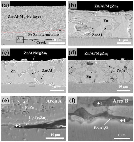
Figure 1.
Cross-sectional microstructures of the samples: (a) S0, (b) S1, (c) S3, and (d) S5. (e,f) Magnified images of squared regions A and B in (a,c), respectively.
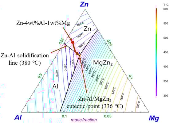
Figure 2.
Calculated solidification path of the Zn-4 wt.%Al-1 wt.%Mg alloy.
In sample S0, interfacial cracking occurred between the coating and substrate. To investigate the causes of the cracking, the substrate/coating interface of sample S0 was compared with that of a representative Si-containing coating (S3) as shown in Figure 1e,f, which present magnified images of the squared regions A and B marked in Figure 1a,c, respectively. The EDS composition analysis results for the points marked in Figure 1e,f are presented in Table 2. Evidently, the crack initiated in a high-Fe-content IMC layer (Γ-phase) adjacent to the substrate/coating interface. Multiple concurrent reactions occur during the wetting of a solid substrate by a liquid metal containing Zn; these reactions include (1) Zn–liquid substrate interfacial wetting, (2) Zn-induced steel dissolution, (3) isothermal solidification of Fe2Al5−xZnx IMCs, (4) solid-state diffusional phase transformations, and (5) solidification of the liquid Zn alloy [10,25,26]. The transient and unstable nature of Fe2Al5−xZnx results in sudden outbursts, which explain the interdiffusion of Fe into the coating and Zn toward the substrate. These outbursts promote the formation of high-Fe-content intermetallic phases (Fe contents: δ (7–11 wt.%), Γ1 (16–19 wt.%), and Γ (20–27 wt.%) at the interface [27]. The Γ1 phase, which is a highly brittle IMC with a hardness of approximately 500 Hv [28], may be damaged due to physical stresses, such as cutting and/or polishing, during sample preparation for microstructural observation, leading to the formation of cracks. While the cutting method employed was consistent among all the specimens, the presence of visible cracks in sample S0 implied that such cracking was an inherent characteristic of the Zn–Al–Mg coating without Si. Figure 1f shows that the addition of Si results in the formation of a stable interfacial layer of Fe2Al3Si, which is identified by the EDS analysis performed at point 4. This interfacial layer contributed to the strong coating adhesion observed in the Si-containing samples S1–S5.
Table 2.
Phase compositions obtained (via EDS analysis) at the spots marked in Figure 1e,f.
The corresponding electron probe microanalysis (EPMA) phase maps of samples S0 and S3 are displayed in Figure 3a,b, respectively. The EPMA results are consistent with the SEM data. The phase maps of S0 indicate that a significant amount of Fe is out-diffused and distributed inside the coating layer. However, the Fe content in the coating layer in sample S3 was significantly lower than that in sample S0. These results suggested that the dissolved Fe was in the solid solution along with the Si present in the Zn–Al and Zn–MgZn2–Al alloy phase regions. In Figure 3b, Al is predominantly observed in the Zn–Al binary eutectic phase and at the interface, whereas Mg is detected in the ternary eutectic phase and near the surface. In addition, Si is prominent at the interface and coating surface. These results confirm the formation of a stable FeAl3Si interlayer and its ability to inhibit the formation of a brittle Fe–Zn IMC layer.
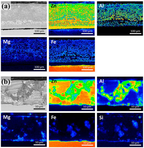
Figure 3.
Elemental distribution in the cross-sections of the Zn-4 wt.%Al-1 wt.%Mg alloy coatings: (a) S0 and (b) S3.
Figure 4 presents the calculated phase diagrams and solidification behavior of the Zn-4%Al-1%Mg ternary alloy with and without Si addition; these diagrams and results were obtained using FactSage. Figure 4a,b illustrate the alloy phases formed as the Fe content varied from 0 to 5 wt.% when the steel sheet was immersed in molten Zn-4%Al-1%Mg and Zn-4%Al-1%Mg-0.5%Si at 600 °C, respectively. In the absence of Si, various Al–Fe IMCs formed in all the composition ranges. However, for the coating containing 0.5 wt.% of Si (Figure 4b), the Al3FeSi IMC formed when the Fe content was <4 wt.%. Figure 4c,d show the phase transformation behavior when the molten alloys with compositions of Zn-4 wt.%Al-1 wt.%Mg and Zn-4 wt.%Al-1 wt.%Mg-0.5 wt.%Si were solidified by cooling from 600 to 100 °C. For the calculations, Fe contents of 2 and 0.5 wt.% were selected to represent conditions wherein significant Fe alloying occurred owing to the absence of Si and where Fe dissolution was impeded by the addition of Si, respectively. As shown in Figure 4c, in the absence of Si, the Fe2Al5 IMC forms at the interface immediately after the immersion of the steel in the molten bath. In contrast, with the addition of 0.5 wt.% of Si, primarily Al3FeSi IMC phases form at the interface, as shown in Figure 4d. The corresponding solidification onset temperature was slightly lower than that of the without-Si sample, leading to a narrower mushy zone.
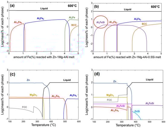
Figure 4.
Thermodynamically calculated phase diagrams of (a) S0 and (b) S5. Thermodynamically calculated solidification behavior of (c) S0 and (d) S5.
Figure 5 shows surface images of the Zn-4%Al-1%Mg alloy coating layers with and without Si addition. The presence of primary Zn, dendritic Zn/Al eutectoid, and Zn/Al/MgZn2 ternary eutectic structures on the surface aligns with the previous cross-sectional observations. In the Si-free coating layer shown in Figure 5a, granular polyhedral Fe2Al5−xZnx IMC particles, which were identified through XRD analyses, were observed on the surface. However, in Figure 5b–d, in addition to the Zn/Al/Mg alloy phases, needle-shaped IMCs are evident on the surface of the Si-containing coatings. EDS mapping was conducted on sample S5 to determine the Mg and Si distributions, and the corresponding results are shown in Figure 5e,f, respectively.
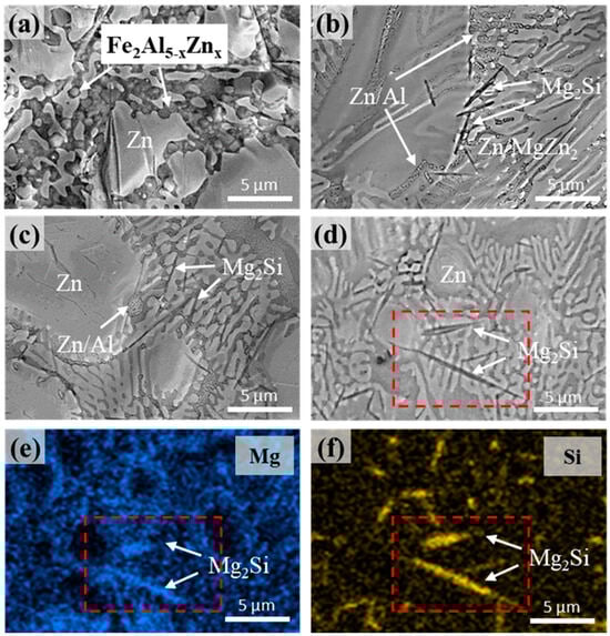
Figure 5.
Surface microstructures of the samples: (a) S0, (b) S1, (c) S3, and (d) S5. (e) Mg and (f) Si distributions in sample S5.
High-resolution XRD analyses were performed to evaluate the effects of the Si content on the crystallographic properties of the Zn–Al–Mg–xSi alloy coatings, and the corresponding patterns are shown in Figure 6. In the patterns of the Si-containing coating layers, distinctive peaks corresponding to Zn, Zn/Al eutectoid, and Zn/Al/MgZn2 eutectic structures, such as Zn, MgZn2, and Al phases, were identified. Conversely, in the pattern of Si-free coating, numerous peaks associated with Fe2Al5−xZnx phases were observed, in addition to peaks corresponding to Zn and MgZn2. This result is attributed to the absence of Si, which results in a reaction between Al and the Fe dissolved from the substrate, leading to the formation of an Fe2Al5−xZnx alloy phase. No peaks associated with the Mg–Si alloy phase were detected in the pattern of the Si-containing coating layers, probably owing to the insufficient quantity of the Mg–Si alloy.
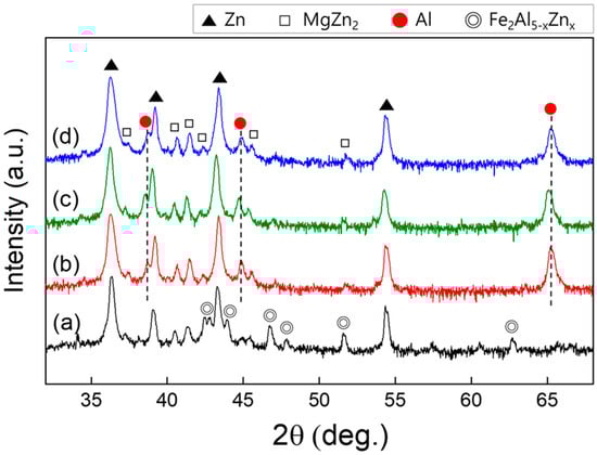
Figure 6.
XRD patterns of the Zn-4 wt.%Al-1 wt.%Mg alloy coatings: (a) S0, (b) S1, (c) S3, and; (d) S5.
An additional examination of the acicular Mg–Si IMC was performed using HR-TEM, and the results are shown in Figure 7. The region outlined by a dotted line in Figure 7a was analyzed by selected-area electron diffraction (SAED), and the result reveals that the Mg–Si IMC phase corresponds to Mg2Si with a face-centered cubic structure. This identification result is supported by the interplanar distances (d-spacing) calculated using the ImageJ software, corresponding to the respective planes marked in Figure 7b, in accordance with ICDD card #00-035-0773 (Mg2Si). The reported densities of liquid Zn, Al, and Mg were 6.57, 2.34, 1.57 g/cm3, respectively, and that of solid Mg2Si was 1.98 g/cm3 [29]. Therefore, based on these results, we can infer that the preferentially solidified Mg2Si floats toward the liquid surface and subsequently undergoes final solidification. Mg2Si solidifies and precipitates within the grain boundaries and Zn–Al–MgZn2 ternary phases; it possibly reduces the surface roughness (Ra) of the coating layer. This result is corroborated by the photographs and 3D surface morphologies of the samples presented in Figure 8 and Figure 9, respectively. The average surface roughness (Ra) was determined from the surface maps using the NSworks software. The Ra for S0 was 4.45 µm, which significantly decreased to 1.39, 0.77, and 0.31 µm for S1, S3, and S5, respectively.
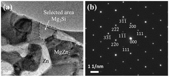
Figure 7.
TEM analysis of the Zn-4 wt.%Al-1 wt.%Mg-0.3 wt.%Si alloy coatings: (a) TEM bright-field image; (b) SAED patterns of the region outlined by the dotted line in (a).
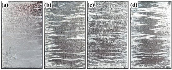
Figure 8.
Photographs of the Zn-4 wt.%Al-1 wt.%Mg alloy coatings: (a) S0, (b) S1, (c) S3, and (d) S5.
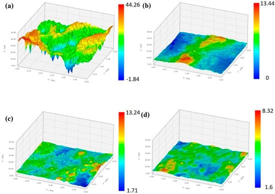
Figure 9.
3D surface topographies of (a) S0, (b) S1, (c) S3, and (d) S5.
Adhesive tape was applied to the 2T-bent surface of the samples to assess their coating adhesion. The appearance of the peeled-off coating layers after tape removal is shown in Figure 10. The delaminated area measured by an image analyzer was 26.66% for sample S0, signifying poor coating adhesion, which might be attributed to the development of a brittle Γ1-Fe5Zn21 IMC phase at the interface between the coating layer and substrate. In contrast, no peeling was observed in the Si-containing samples.
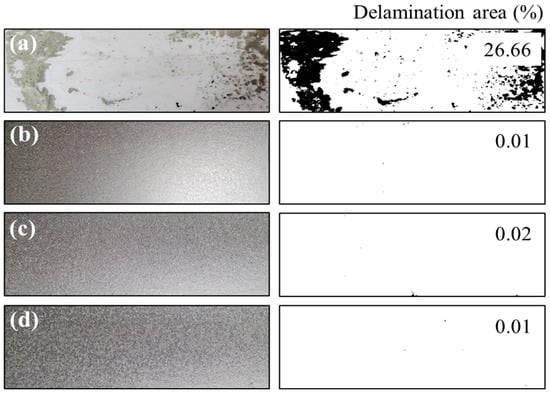
Figure 10.
Coating-adhesion evaluation with an attached tape (on the left) and the corresponding peeled-off area fractions (on the right) for (a) S0, (b) S1, (c) S3, and (d) S5.
To investigate the influence of Si addition on the electrochemical characteristics of the alloy coatings, the samples were subjected to potentiodynamic polarization tests, and the corresponding plots are depicted in Figure 11. Commercial hot-dip galvanized steel (GI) sheets were also tested for comparison. The corrosion potential and corrosion current densities derived from Tafel extrapolation are presented in Table 3. The polarization results indicate that the addition of Si induces a positive shift in the corrosion potential; this positive shift is attributed to the suppression of anodic reactions and electron transfer through the coating [30,31]. The corrosion current density decreases with the increasing Si content, indicating suppression of the anodic reaction on the sample surface, and consequently, the corrosion rate decreases as well. According to surface microstructural and electrochemical analyses, the improved corrosion resistance is attributed to the presence of IMCs containing Al and Mg, along with acicular Mg2Si precipitates, on the coating surface. The rapid sacrificial dissolution of the Si-containing intermetallic phases can suppress local corrosion in the ternary eutectic areas by inducing the formation of Si-based oxides and Zn5(OH)8Cl·H2O on the surface [32].
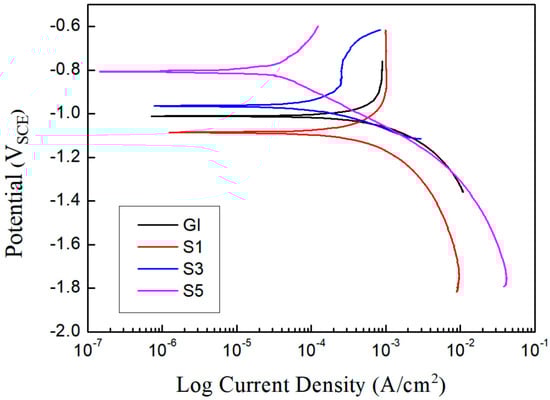
Figure 11.
Potentiodynamic polarization plots of the hot-dip Zn–Al–Mg–xSi alloy-coated steel sheets.
Table 3.
Electrochemical corrosion parameters of the hot-dip Zn–Al–Mg–xSi alloy-coated steel sheets.
An SST was conducted to evaluate the corrosion resistance of the Zn–Al–Mg–xSi alloy-coated steel sheets. A GI steel sheet was also tested for comparison, and sample S0 was excluded from the evaluation because of coating delamination. Figure 12 shows that the corrosion resistances of all the Zn–Al–Mg–Si coatings were significantly higher than those of GI. White rust was observed over the entire surface of the GI steel after 20 h, and red rust began to appear after 200 h. In contrast, on the Si-containing alloy-coated samples S1, S3, and S5, white rust formed after 600, 1000, and 1000 h, respectively, indicating the occurrence of delayed white rusting in these samples. After 2400 h, red rust began to appear on the surfaces of S1 and S3, whereas sample S5 did not show the formation of red rust even after 2600 h. These SST results align with the electrochemical potentiodynamic polarization results, demonstrating that SI addition increases the corrosion resistance of the coatings.
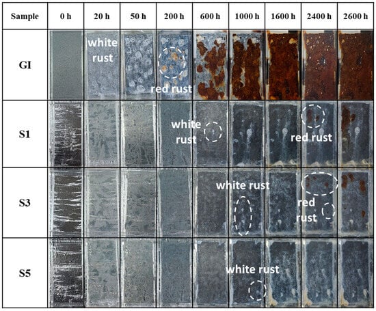
Figure 12.
SST results of the hot-dip Zn–Al–Mg–xSi alloy-coated steel sheets.
4. Conclusions
The effects of Si addition to batch-type hot-dip Zn–Mg–Al alloy coatings on their microstructure, electrochemical behavior, and corrosion resistance were investigated. The major results are summarized below:
- Si addition improves the microstructure, electrochemical behavior, and corrosion resistance of Zn–Mg–Al alloy coatings.
- Fe–Zn IMC layers form in the Zn–Al–Mg coatings owing to the dissolution of a large amount of Fe during the dipping process.
- Coating delamination, along with crack formation, occurs at the interface owing to the formation of brittle Fe–Zn IMCs.
- Si addition leads to the formation of a stable Fe2Al3Si inhibition layer, which suppresses interdiffusion and enhances coating adhesion.
- Si addition induces acicular Mg2Si IMC formation at the grain boundaries and in the ternary alloy region, thereby reducing the surface roughness.
- The observed superior long-term performance of the coatings indicates that their corrosion resistance improves with increasing Si content.
- In the SST, no red rust is observed on the sample coating containing 0.5 wt.% of Si even after 2600 h.
Author Contributions
Conceptualization, S.-M.S. and M.-S.O.; methodology, S.G. and E.-P.K.; validation, M.-S.O.; investigation, S.-M.S., E.-P.K. and M.-S.O.; data curation, S.-M.S.; writing—original draft preparation, S.-M.S.; writing—review and editing, S.G. and M.-S.O. All authors have read and agreed to the published version of the manuscript.
Funding
This work was supported by the [National Research Foundation of Korea (NRF)] grant funded by the Korea Government (Ministry of Science and ICT) [No. 2022R1A2C1008972]. This work was also supported by “Human Resources Program in Energy Technology” of the Korea Institute of Energy Technology Evaluation and Planning (KETEP), granted financial resource from the Ministry of Trade, Industry & Energy, Republic of Korea. (No. 20204010600470).
Data Availability Statement
Data are contained within the article.
Acknowledgments
Authors thank researchers in the Center for University-wide Research Facilities (CURF) at Jeonbuk National University, for their assistance with FE-SEM analysis.
Conflicts of Interest
Author Seong-Min So iss employed by the company Hyundai Steel. The remaining authors declare that the research was conducted in the absence of any commercial or financial relationships that could be construed as a potential conflict of interest.
References
- Hoque, M.A.; Yao, C.W.; Lian, I.; Zhou, J.; Jao, M.; Huang, Y.C. Enhancement of corrosion resistance of a hot-dip galvanized steel by superhydrophobic top coating. MRS Commun. 2022, 12, 415–421. [Google Scholar] [CrossRef]
- Chakraborty, A.; Ghosh, R.; Sudan, M.; Mondal, A. Improvement in hot dip galvanized coating microstructure and properties by pre-metallic deposition on steel surface: A comprehensive review. Surf. Coat. Technol. 2002, 449, 128972. [Google Scholar] [CrossRef]
- Ding, C.; Ma, Z.; Liu, S.; Zhao, J.; Luo, Q.; Liu, H.; Wu, G.; Zhang, J. Research on design and microstructure of hot-dip Zn-Al-Mg/Sn alloy. Mater. Charact. 2022, 185, 111746. [Google Scholar] [CrossRef]
- Kania, H.; Bierońska, M. Corrosion resistance of Zn-31AlMg coatings obtained by batch hot dip method. Solid State Phenom. 2014, 212, 167–172. [Google Scholar] [CrossRef]
- Oh, M.S.; Kim, S.H.; Kim, J.S.; Lee, J.W.; Shon, J.H.; Jin, Y.S. Surface and cut-edge corrosion behavior of Zn-Mg-Al alloy-coated steel sheets as a function of the alloy coating microstructure. Met. Mater. Int. 2016, 22, 26–33. [Google Scholar] [CrossRef]
- Lim, Y.; Jang, B.; Koh, J. Effect of welding parameters on porosity formation in weld beads of galvanized steel pipes produced with gas metal arc welding. J. Weld. Join. 2012, 30, 440–444. [Google Scholar]
- Kim, Y.; Shin, K.S.; Jeon, S.H.; Chin, K.G.; Lee, J. The influence of the dew point on the wettability of twinning-induced-plasticity steels by liquid Zn-0.23-wt% Al. Corros. Sci. 2014, 85, 364–371. [Google Scholar] [CrossRef]
- Qiao, C.; Shen, L.; Hao, L.; Mu, X.; Dong, J.; Ke, W.; Liu, J.; Liu, B. Corrosion kinetics and patina evolution of galvanized steel in a simulated coastal-industrial atmosphere. J. Mater. Sci. Technol. 2019, 35, 2345–2356. [Google Scholar] [CrossRef]
- Bian, J.; Zhu, Y.; Liu, X.; Wang, G. Development of Hot Dip Galvanized Steel Strip and Its Application in Automobile Industry. J. Iron Steel Res. Int. 2006, 13, 47–50. [Google Scholar] [CrossRef]
- Chen, L.; Fourmentin, R.; McDermid, J.R. Morphology and kinetics of interfacial layer formation during continuous hot-dip galvanizing and galvannealing. Metall. Mater. Trans. A 2008, 39, 2128–2142. [Google Scholar] [CrossRef]
- Kim, K.; Grandhi, S.; Oh, M.S. Improving the Coatability of Zn–Mg–Al Alloy on Steel Substrate by the Surface Pretreatment of SnCl2-Added Zinc Ammonium Chloride. Appl. Sci. 2023, 13, 950. [Google Scholar] [CrossRef]
- Manna, M. Effect of Fluxing Chemical: An Option for Zn-5wt.%Al Alloy Coating on Wire Surface by Single Hot Dip Process. Surf. Coat. Technol. 2011, 25, 3716–3721. [Google Scholar] [CrossRef]
- Du, A.; Huo, Y.; Hu, J. Study of Fluxing Process for Hot Dipping Galfan Alloy on Steel Wire. Adv. Mater. Res. 2012, 383–390, 1901–1904. [Google Scholar] [CrossRef]
- Shibli, S.M.A.; Manu, R.; Dilimon, V.S. Effect of nickel-rich barrier layer on improvement of hot-dip zinc coating. App. Surf. Sci. 2005, 245, 179–185. [Google Scholar] [CrossRef]
- Manna, M.; Dutta, M. Improvement in galvanization and galvannealing characteristics of DP 590 steel by prior Cu or Cu–Sn flash coating. Surf. Coat. Technol. 2014, 251, 29–37. [Google Scholar] [CrossRef]
- Samanta, S.A.; Halder, K.; Deo, Y.; Guha, S.; Dutta, M. Effect of Mn and Cr on the selective oxidation, surface segregation and hot-dip Zn coatability. Surf. Coat. Technol. 2019, 377, 124908. [Google Scholar] [CrossRef]
- Xu, B.; Phelan, D.; Dippenaar, R. Role of silicon in solidification microstructure in hot-dipped 55wt% Al–Zn–Si coatings. Mater. Sci. Eng. A 2008, 473, 76–80. [Google Scholar] [CrossRef]
- Honda, K.; Ushioda, K.; Yamada, W. Influence of Si Addition to the Coating Bath on the Growth of the Al–Fe Alloy Layer in Hot-dip Zn–Al–Mg Alloy-coated Steel Sheets. ISIJ Int. 2011, 51, 1895–1902. [Google Scholar] [CrossRef]
- Li, K.; Liu, Y.; Tu, H.; Su, X.; Wang, J. Effect of Si on the growth of Fe-Al intermetallic layer in Zn-11%Al-3%Mg coating. Surf. Coat. Technol. 2016, 306, 390–396. [Google Scholar] [CrossRef]
- Chen, R.Y.; Willis, D.J. The Behavior of Silicon in the Solidification of Zn-55Al-1.6Si Coating on Steel. Metall. Mater. Trans. A 2005, 36, 117–128. [Google Scholar] [CrossRef]
- Lee, J.W.; Kim, S.J.; Oh, M.S. Influence of Alloy Content on Microstructure and Corrosion Resistance of Zn-Based Alloy Coated Steel Product. J. Korean Inst. Met. Mater. 2020, 58, 169–174. [Google Scholar] [CrossRef]
- Bale, C.W.; Bélisle, E.; Chartrand, P.; Decterov, S.A.; Eriksson, G.; Hack, K.; Jung, I.H.; Kang, Y.B.; Melançon, J.; Pelton, A.D.; et al. FactSage thermochemical software and databases—Recent developments. Calphad 2009, 33, 295–311. [Google Scholar] [CrossRef]
- Selverian, J.H.; Marder, A.R.; Notis, M.R. The Reaction between Solid Iron and Liquid AI-Zn Baths. Metall. Trans. A 1988, 19, 1193–1203. [Google Scholar] [CrossRef]
- ASTM E290-22; Standard Test Methods for Bend Testing of Material for Ductility. ASTM International: West Conshohocken, PA, USA, 2022.
- Okamoto, N.L.; Kashioka, D.; Inomoto, M.; Inui, H.; Takebayashi, H.; Yamaguchi, S. Compression deformability of Γ and ζ Fe-Zn intermetallics to mitigate detachment of brittle intermetallic coating of galvannealed steels. Scr. Mater. 2013, 69, 307–310. [Google Scholar] [CrossRef]
- Marder, A.R. Metallurgy of zinc-coated steel. Progr. Mater. Sci. 2000, 45, 191–271. [Google Scholar] [CrossRef]
- Lee, I.; Han, K.; Ohnuma, I.; Kainuma, R. Experimental determination of phase diagram at 450 °C in the Zn–Fe–Al ternary system. J. Alloys Compd. 2021, 854, 157163. [Google Scholar] [CrossRef]
- Biswas, S.; Das, S.; Jena, S.; Mitra, A.; Das, S.; Das, K. Pulse potentiostatic deposition of Fesingle bondZn based intermetallic coatings and evaluation of its catalytic activity for hydrogen evolution reaction. Surf. Coat. Technol. 2020, 402, 126299. [Google Scholar] [CrossRef]
- Ishikawa, M.; Nakamura, T.; Hirata, S.; Iida, T.; Nishio, K.; Kogo, Y. Mechanical properties of Mg2Si with metallic binders. Jpn. J. Appl. Phys. 2015, 54, 07JC03. [Google Scholar] [CrossRef]
- Srimaneepong, V.; Rokaya, D.; Thunyakitpisal, P.; Qin, J.; Saengkiettiyut, K. Corrosion resistance of Graphene oxide/Silver coatings on Ni–Ti alloy and Expression of IL-6 and IL-8 in Human oral fibroblasts. Sci. Rep. 2020, 10, 3247. [Google Scholar] [CrossRef]
- Zhou, H.; Wang, Y.; Ma, T. Effect of silicon addition on corrosion behavior of carbon steel rebar in sulfuric acid environment. Int. J. Electrochem. Sci. 2020, 15, 3003–3012. [Google Scholar] [CrossRef]
- Lee, J.W.; Son, I.; Kim, S.J. Newly designed surface control using Si addition in trace quantity for Zn-2Al-3Mg alloy coated steel sheet with improved corrosion resistance. Appl. Surf. Sci. 2022, 598, 153868. [Google Scholar] [CrossRef]
Disclaimer/Publisher’s Note: The statements, opinions and data contained in all publications are solely those of the individual author(s) and contributor(s) and not of MDPI and/or the editor(s). MDPI and/or the editor(s) disclaim responsibility for any injury to people or property resulting from any ideas, methods, instructions or products referred to in the content. |
© 2024 by the authors. Licensee MDPI, Basel, Switzerland. This article is an open access article distributed under the terms and conditions of the Creative Commons Attribution (CC BY) license (https://creativecommons.org/licenses/by/4.0/).