Abstract
Metamaterials are artificial materials with properties depending mainly on their designed structures instead of their materials. Pentamode metamaterials are one type of metamaterial. They have solid structures with fluid-like properties, which can only withstand compressive stresses, not shear stresses. Two-dimensional pentamode metamaterials are easier to manufacture than three-dimensional models, so they have received wide attention. In this review, the properties, manufacturing, and applications of two-dimensional pentamode metamaterials will be discussed. Their water-like properties are their most important properties, and their velocities and anisotropy can be designed. They can be processed by wire-cut electrical discharge machining, waterjet cutting, and additive manufacturing techniques. They have a broad application prospect in acoustic fields such as acoustic stealth cloaks, acoustic waveguides, flat acoustic focusing lenses, pentamode acoustic meta-surfaces, etc.
1. Introduction
Metamaterials, a concept first articulated by Professor Rodger M. Walser of the University of Texas at Austin [1,2], represent a revolutionary class of composite materials engineered from artificial structural units [3,4,5]. These materials transcend the inherent limitations of natural material properties, facilitating the deliberate manipulation of sound wave propagation pathways. Unlike conventional composites, the characteristics of metamaterials stem from their structure, rather than their constituent substances, enabling the realization of properties and functionalities beyond those found in nature [5,6,7]. The domain of metamaterials, encompassing electromagnetic, mechanical, acoustic, and thermal variants, is expanding rapidly [8], fostering the development of innovative applications, such as microwave imaging, acoustic stealth, and thermal camouflage.
Acoustic metamaterials, a significant subset of metamaterials, can offer unparalleled control over sound waves, leading to extraordinary capabilities [9,10,11,12,13,14,15,16], including invisibility cloaks that render obstacles undetectable [17,18], meta-surfaces that guide and control sound trajectories [19,20,21], and flat acoustic lenses with the power to concentrate sound waves [22]. Pentamode metamaterials (PMs) are one kind of acoustic metamaterials, and maintain fluid-like properties. They can be classified into two-dimensional PMs and three-dimensional PMs. Two-dimensional PMs are easier to fabricate than three-dimensional PMs, and several manufacturing methods can be utilized. The potential applications of two-dimensional PMs are broad, especially in the acoustic field. They are envisioned to contribute significantly to the development of acoustic stealth technologies like cloaking devices, which can render objects invisible to sound waves. Additionally, they can be used to create acoustic waveguides, flat acoustic focusing lenses, and pentamode acoustic meta-surfaces, all of which can revolutionize the manipulation of sound in various environments.
Analyzing these materials enables the design of devices that can control acoustic waves with unprecedented precision, potentially leading to breakthroughs in fields such as medical imaging, underwater communication, and noise control systems. Therefore, the comprehensive study of two-dimensional PM properties, manufacturing methods, and applications is not only of scientific interest, but also of great technological and industrial significance.
2. Types and Properties of Two-Dimensional PMs
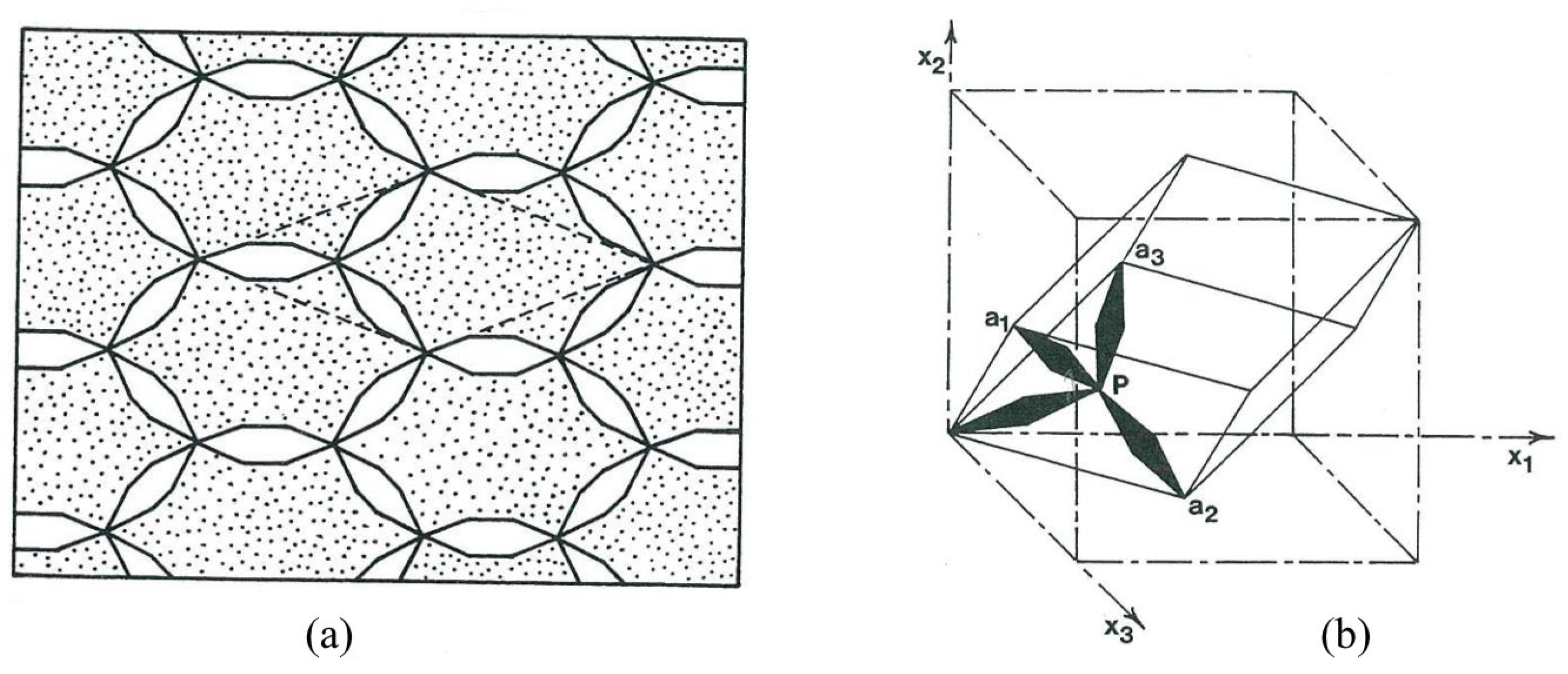
In 1995, Milton and Cherkaev [23] introduced the concepts of two-dimensional bimode and three-dimensional pentamode metamaterials, as shown in Figure 1. For two-dimensional materials, the stiffness matrix C is a positive definite symmetric matrix that links the stress and strain through the relation:

Figure 1.
Bimode materials and pentamode metamaterials [23]: (a) bimode materials and (b) pentamode metamaterial unit cell.
Here, τ represents stress, ε represents strain, and C represents the stiffness matrix of the material, which is a positive definite symmetric matrix. The stiffness matrix C can be diagonalized by orthogonal transformation and expressed in the following form:
where and the eigenvalues for the common materials. λ1, λ2, and λ3 are the eigenvalues of matrix C, which represent the stiffness of the material along the three main directions in the coordinate system defined by Q. If three eigenvalues are all large, the material is named nullmode material. If two eigenvalues are very large and one is small, the material is named unimode material. If one eigenvalue is very large and two eigenvalues are small, the material is named bimode material.
For the stiffness matrix of three-dimensional materials, there are six eigenvalues. If five of them are very small, the material is named pentamode material. Moreover, three-dimensional materials can be nullmode, unimode, bimode, trimode, or quadmode materials. Both two-dimensional bimode and three-dimensional pentamode materials have one non-zero eigenvalue. Therefore, two-dimensional bimode materials are typically referred to as two-dimensional PMs. It has been pointed out that, when the ratio of the bulk modulus to the shear modulus (K/G) tends to infinity, it can prevent the coupling of pressure waves and shear waves. For ideal fluids, the shear modulus is zero, and the same holds true for ideal PMs. Hence, pentamode metamaterial is also referred to as a “superfluid” [23,24,25].
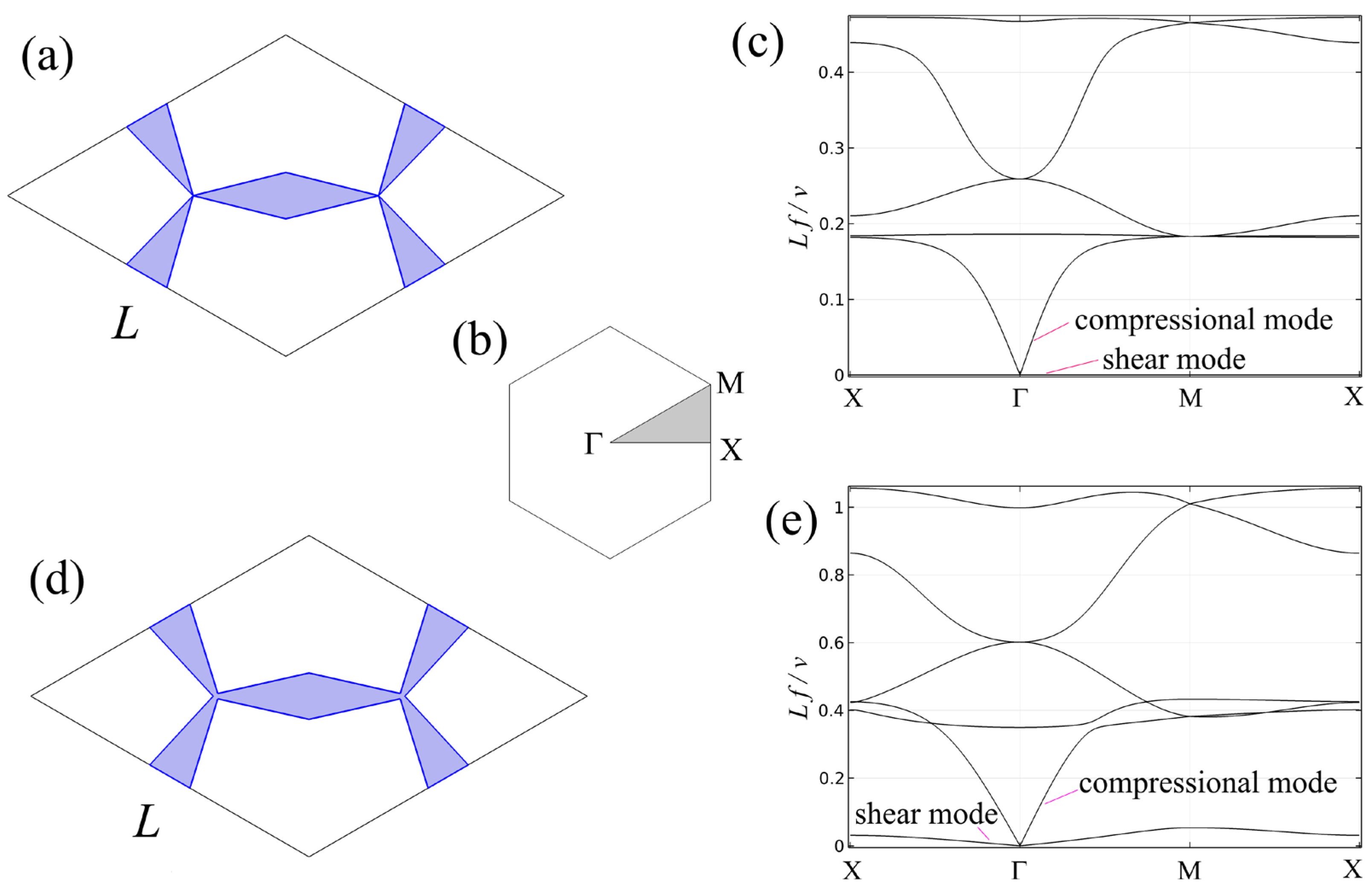
The properties of acoustic metamaterials can be derived from the band structure of their unit cells. For a three-dimensional metamaterial with face-centered cubic (FCC) cells, researchers have calculated the band structure and discovered the existence of a pentamode band with a single compression mode. This means that, in this band structure, only compressional waves can propagate through the material, and other wave modes are prohibited or greatly suppressed [26]. For ideal two-dimensional PMs, the cones touch each other with vertices. To apply boundary conditions conveniently, the primitive cell is transformed by cutting through the middle of the arms, as Figure 2a shows. The Brillouin zone of the rhombic cell is a hexagon, as Figure 2b shows, and the shaded area is the irreducible Brillouin zone. COMSOL Multiphysics software 6.2 is used to solve the band structures of the unit cell with Floquet-periodic boundary conditions along the borders of the irreducible Brillouin zone. The band structures of the ideal two-dimensional PM are shown in Figure 2c. There is only a compressional mode at the long-wavelength range, and the shear mode is zero. However, ideal two-dimensional PMs do not exist, because the structure will fall apart in the real world. Practical two-dimensional PMs are obtained when the dimensions of the joints are finite, as shown in Figure 2d. The band structures of the practical primitive cell are shown in Figure 2e. It can be seen from the figure that shear mode is introduced at a low-frequency range. This is unavoidable, due to the finite dimensions of the joints. Fortunately, there is a frequency range where only the compressional mode exists. The frequency range of pentamode materials varies with the dimensions of the structures.

Figure 2.
Two-dimensional PM unit cells and their band structures: (a) ideal two-dimensional PM unit cell; (b) Brillouin zone of the rhombic unit cells; (c) band structures of (a); (d) practical two-dimensional PM unit cell; and (e) band structures of (d).
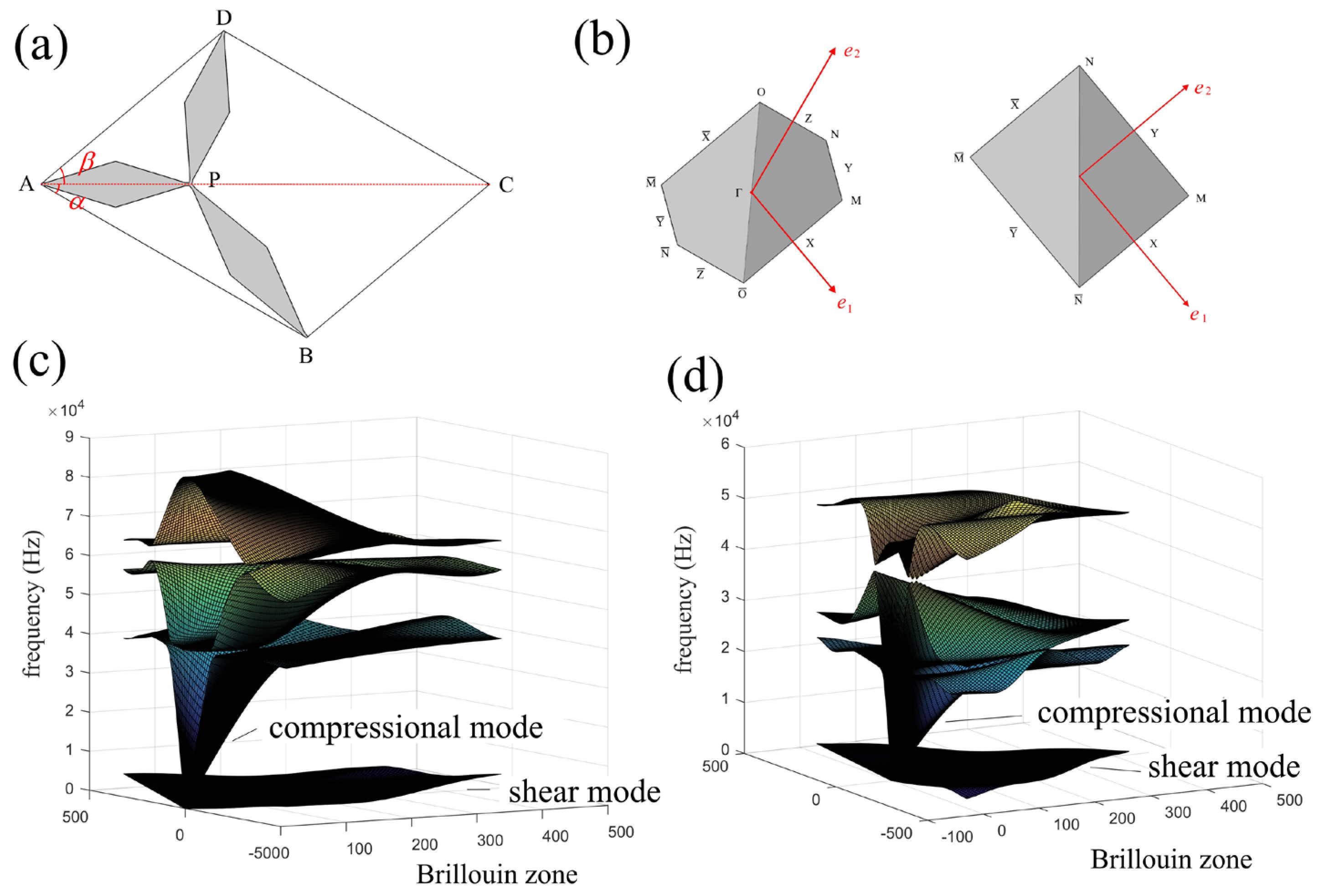
Besides the rhombic cells, other types of parallelograms can also be used as pentamode unit cells [27], which provide more adjustable parameters for studying the characteristics of two-dimensional PMs. A unit cell of a parallelogram is shown in Figure 3a. By changing the angles α and β, different unit cells can be obtained. More specifically, if the sum of α and β equals 90°, a rectangle is obtained. The Brillouin zones of parallelogram-shaped and rectangular unit cells are shown in Figure 3b. The band structures over half of their Brillouin zones are shown in Figure 3c,d. Within certain frequency ranges, there are only compressional modes, while shear modes exist only at lower and higher frequencies. Anisotropy is introduced for these unit cells and varies as the shape of the unit cell changes. The position of joint P can also be changed to alter the effective properties and anisotropy.
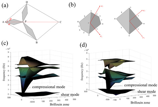
Figure 3.
Two-dimensional PMs with arbitrary unit cells [27]: (a) microstructure of unit cells, (b) the Brillouin zones of parallelogram-shaped and rectangular unit cells, (c) band structures of a unit cell with α = 30° and β = 40°, and (d) band structures of unit cells with α = 50° and β = 40°.
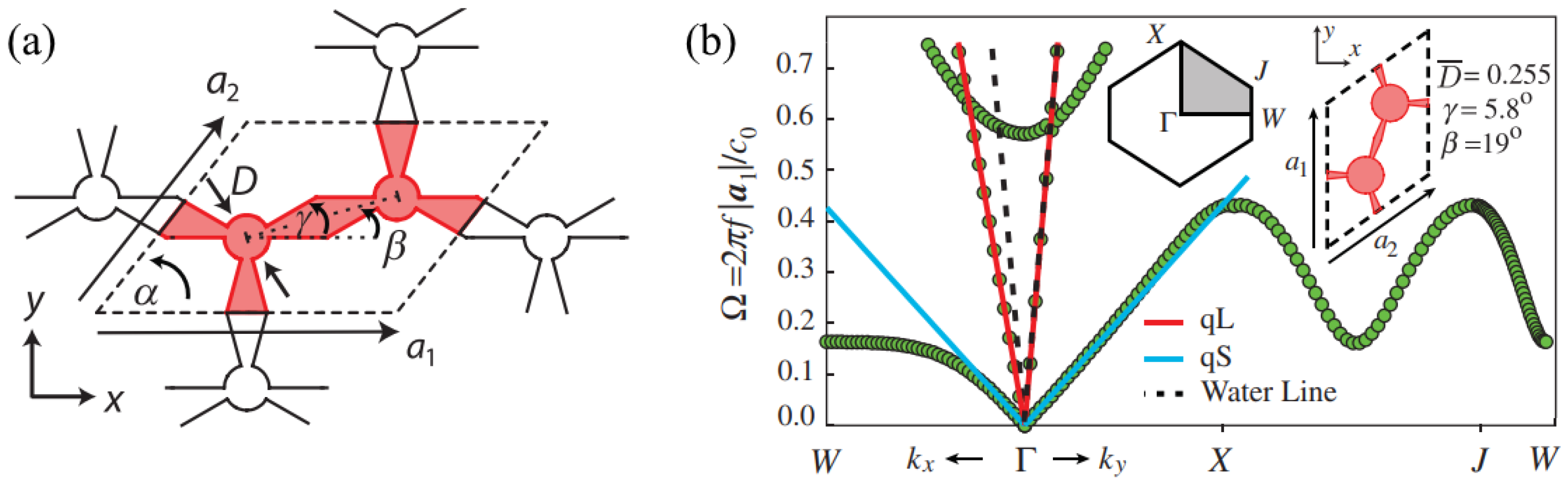
Similarly, Layman et al. [28] used parallelograms as basic unit cells to construct a slanted honeycomb lattice, as shown in Figure 4a. The struts were connected by circular joints, and the dimension of the joints were an important parameter in affecting the effective properties. The band structures of a unit cell are shown in Figure 4b. The compressional wave velocity was much larger than the shear wave velocity, and there was a frequency range where only the compressional mode existed. The bulk effective properties were tuned with variation in the cell geometry and structure parameters. High anisotropy was achieved. The anisotropy in the stiffness of the unit cells can exceed three orders of magnitude, which is highly advantageous for many acoustic devices that require anisotropy.
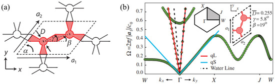
Figure 4.
A type of two-dimensional PM and tuning effective properties [28]: (a) microstructures of the unit cell and (b) band structures of the unit cells.
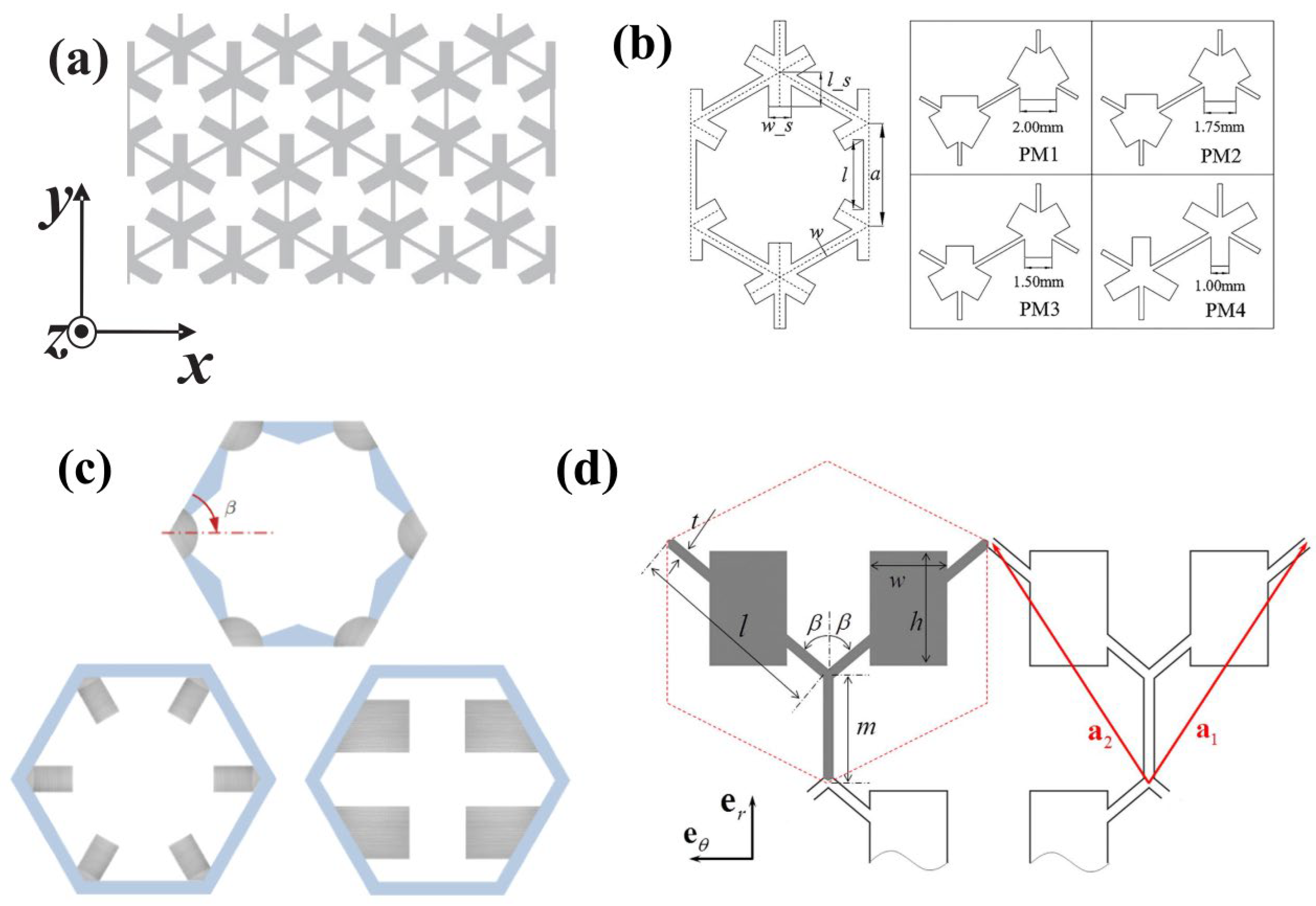
Honeycomb structures are the basic units of two-dimensional PMs. Additional masses can be added to tune the effective properties of two-dimensional PMs. Honeycomb structures with star arms arranged at the joints, as shown in Figure 5a, were proposed by Hladky-Hennion et al. [22]. The effective density, bulk modulus, and shear modulus can be tuned to 1000 kg/m3, 2.25 GPa, and 0.065 GPa, respectively, which are close to those of water. Cai et al. [29] studied four types of unit cells with different star arms at the joints. They found that, in PMs, the acoustic wave might propagate with two different propagation modes, i.e., the longitudinal wave mode and the bending mode. If the longitudinal wave mode dominates, the PMs will exhibit the same acoustic properties as fluids. Conversely, if the bending mode plays a dominant role, the acoustic properties will be entirely different. Additional masses can be added to other parts besides the joints, as shown in Figure 5c,d [30,31]. The structures introduced more parameters to alter the effective properties. The structures can be used to build materials that work similarly to water, and they can introduce anisotropy to build amazing acoustic devices.
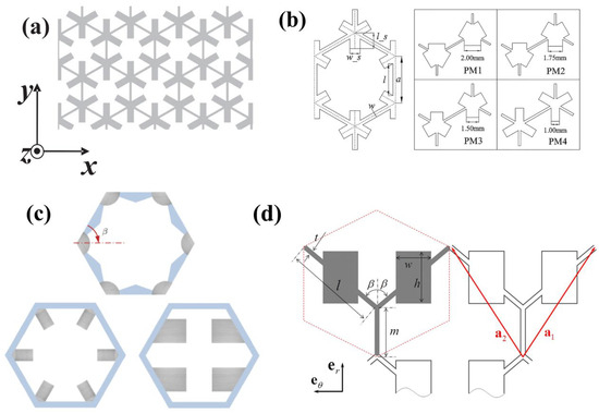
Figure 5.
Two-dimensional PMs of honeycomb structures with masses: (a) honeycomb lattice with additional masses on the corners [22], (b) honeycomb lattices with different masses on the corners [29], (c) honeycomb lattices with masses on the corners or arms [30], and (d) honeycomb lattice with masses on the arms [31].
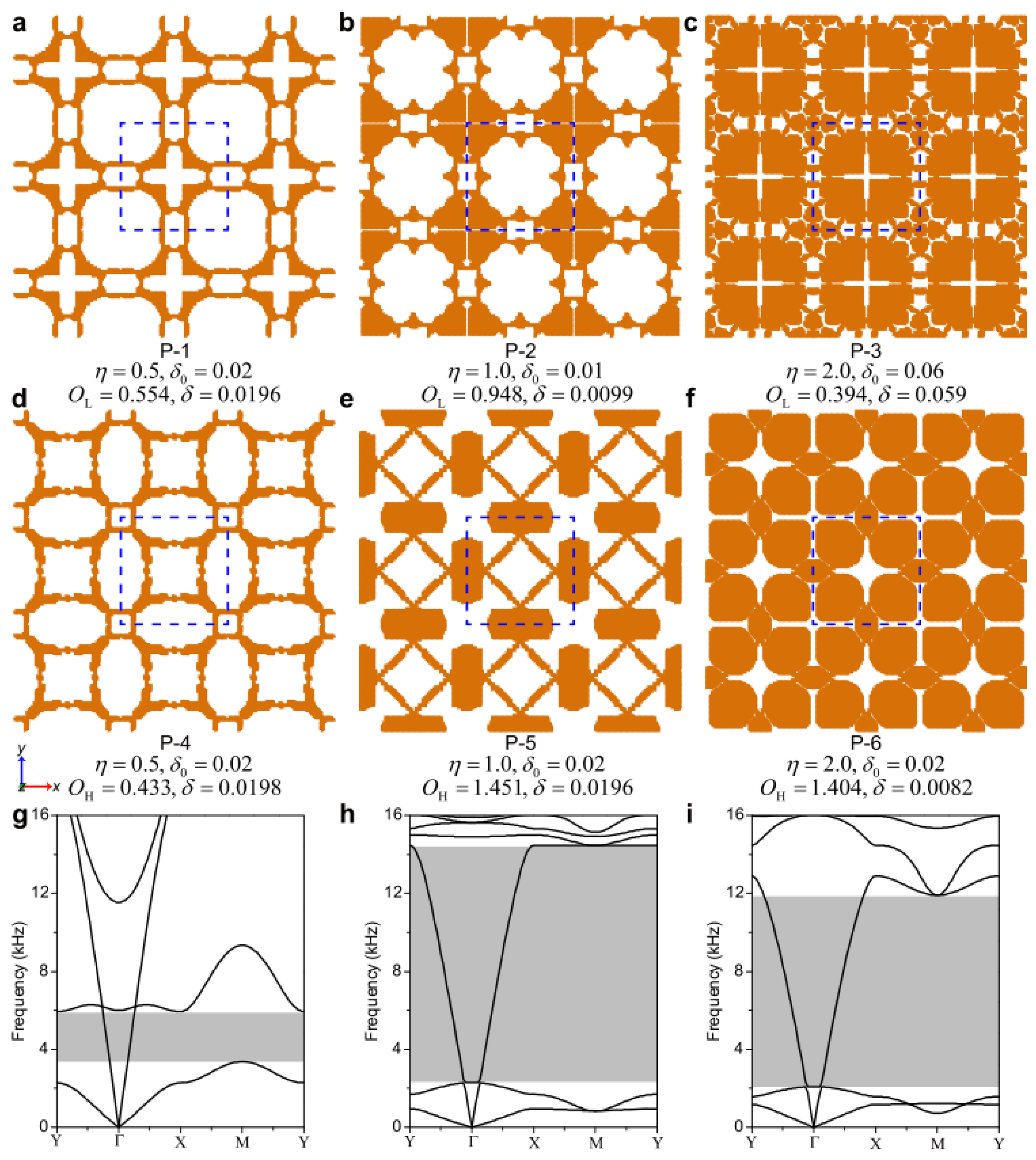
When adjusting the structural parameters of the unit cells, sometimes it is only possible to satisfy one or two of the required property combinations, while not simultaneously meeting all of the performance requirements. In order to design PM units that meet all of the performance requirements, some researchers have proposed topology optimization algorithms. These algorithms systematically design and explore a range of new isotropic or anisotropic PMs [32,33,34]. Multiple sets of results were optimized based on the required equivalent density, elastic modulus, degree of anisotropy, and pentamode characteristics. Some examples of a set of isotropic square lattice PMs with 3 × 3 unit cell configuration are shown in Figure 6 [32]. The region enclosed by the central blue dashed line in each model represents one unit cell. Compared to traditional PMs, their structures become highly complex. The band structures (g) to (i) for P-1, P-5, and P-6 are shown, with the shaded regions indicating shear wave band gaps where only compressional waves exist. These unit cells exhibit pentamode characteristics within specific frequency ranges, providing a new approach for the design of PMs.
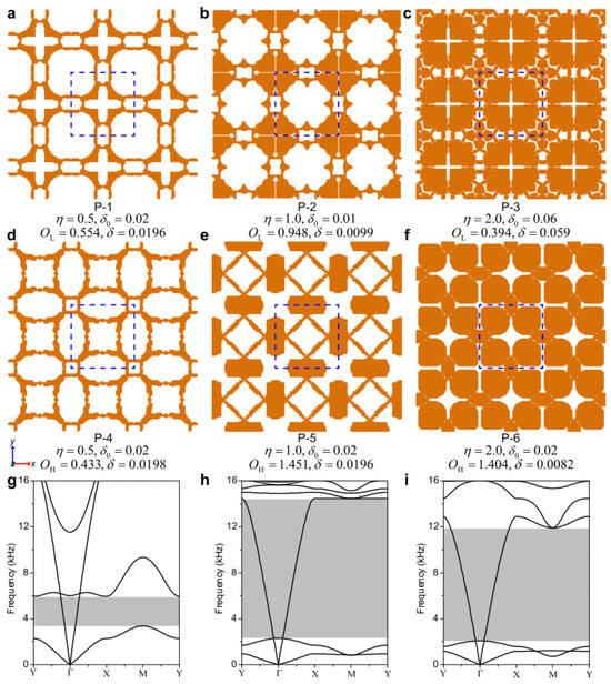
Figure 6.
Several PMs designed with topology and representative band structures: (a–c) Three 3 × 3 microstructures with their representative prescribed η and δ0 using the low-order optimization. (d–f) Three 3 × 3 microstructures with their representative prescribed η and δ0 using the high-order optimization. Dash line represents a C4v-symmetry PM microstructure, (g–i) Dispersion relations from Bloch-wave analysis for P-1 (g), P-5 (h) and P-6 (i), respectively. The shadowed areas represent the bandgaps [32].
3. Manufacturing of Two-Dimensional PMs
Currently, one challenge in experimenting with PMs is the processing method. Compared to three-dimensional volumetric structures, two-dimensional PM structures are planar, and thus easier to process. However, components designed based on PMs often have a wide range of dimensions, with a minimum size of microstructures. Therefore, high precision is required in the manufacturing process. Currently, the primary processing methods for manufacturing PMs include micro-milling, waterjet machining, wire electrical discharge machining (WEDM), and additive manufacturing.
3.1. Micro-Milling Maching
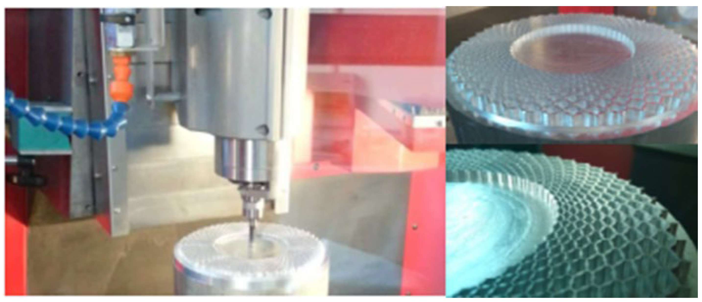
Due to the complexity of the structures of some PMs, conventional mechanical machining may not always meet the processing requirements. For two-dimensional PMs, micro-milling can be used for processing. The Wuhan Second Ship Design and Research Institute [35] used a super-precision micro-milling machining center from the German company KN & G to manufacture a ring-shaped acoustic cloak based on PMs, as shown in Figure 7. The acoustic cloak, with an inner diameter of 75 mm and an outer diameter of 150 mm, is composed of 50 layers, with each layer consisting of 13 identical microstructures. The minimum wall thickness of the machined part is approximately 0.1 mm. While high-precision milling processes offer excellent accuracy, they are often associated with long processing times and high costs, especially when machining extremely small-sized samples. As a result, this method is rarely used for the processing of PMs. Special processing methods are primarily used for the fabrication of metamaterials.
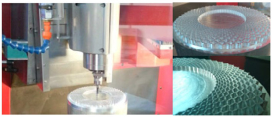
Figure 7.
Micro-milling machining of an acoustic cloak based on PMs [35].
3.2. WaterJet Cutting Technology
Waterjet cutting technology utilizes a high-velocity stream of water to impact and cut materials. It produces relatively smooth cutting surfaces, and the cutting process is less prone to generating heat, making it a safe and environmentally friendly cutting method. Because of these advantages, waterjet cutting technology is widely applied in the fabrication of two-dimensional metamaterials [22,36].
An acoustic lens with negative refraction was designed by Hladky-Hennion et al. [22]. The acoustic lens was a two-dimensional model composed of units of phononic crystals. A cylindrical wave below the lens can be focused at one point above the lens. Waterjet cutting technology was used to fabricate a sample with aluminum as the base material, as shown in Figure 8a. The sample was 75 mm high and 265 mm wide, with thickness of between 58.1 mm and 60 mm. The lens was assembled from 15 aluminum plates, each with a thickness of 5 mm. Another acoustic lens of the gradient index was designed by Su et al. [36]. The lens was assembled from 12 lens pieces and 1-mm-thick neoprene gaskets, alternately, and mounted by two 2-cm-thick aluminum end caps with 4 steel rods, as shown in Figure 8b. Each pentamode plate was 1.5 cm thick and was fabricated using abrasive waterjet cutting technology. The maximum discrepancy was 0.5 mm from the desired dimension, with an average difference of 0.2 mm. The experimental results show that they both have good performance in the focus of acoustic energy.
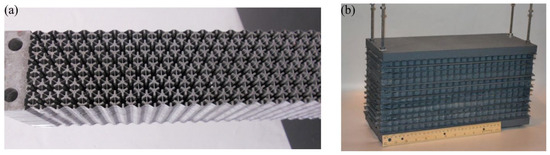
Figure 8.
Acoustic lens based on PMs fabricated with waterjet cutting technology: (a) negative refraction acoustic lens [22] and (b) acoustic lens built with layers of PMs [36].
The thickness of the plate processed by waterjet cutting is limited, and there is some inclination at the theoretically straight sections. However, waterjet cutting technology offers relatively high processing efficiency and, although it is not exceptionally high in precision, can meet general requirements.
3.3. Wire Electrical Discharge Machining
In addition to waterjet cutting technology, WEDM is also a typically used processing technique for two-dimensional PMs. WEDM operates by discharging electrical pulses through an electrode to erode and cut metal workpieces, making it suitable for processing complex and precision small-scale components, especially when dealing with thicker materials or when precision is crucial. The processing accuracy of WEDM can reach as high as 0.002–0.01 mm, and it results in low surface roughness, providing a smooth and polished finish. It is widely used in the fabrication of PMs.
An acoustic cloak is an important device that makes acoustic waves pass around the cloaked object, leaving little or no effect on the surrounding acoustic field. A lot of effort has contributed to the design and fabrication of acoustic cloaks. However, the high anisotropy and inhomogeneity make them difficult produce. Chen et al. [37] proposed a model of a two-dimensional acoustic invisibility cloak with an inner diameter of 200 mm and an outer diameter of 334 mm. Based on PMs, they used wire electrical discharge machining technology to process a 50-mm-thick aluminum block into a ring-shaped cloak, as shown in Figure 9a. Zhao et al. [38] used aluminum as the base material and employed WEDM-LS technology to fabricate a PM that mimicked water in its acoustic properties over a wide range of frequencies. The processing accuracy of the sample was 0.005 mm, and the base metal was titanium alloy TC4 with a dimension of 305.66 × 264.71 × 50.00 mm, as shown in Figure 9b. Zhang et al. [39] fabricated a broadband underwater acoustic reflective meta-surface sample with WEDM-LS technology, as shown in Figure 9c. The dimensions of the fabricated device were 693.5 × 150.7 × 100.0 mm3. The fabricated device comprised a 78.6-mm-thick microstructure layer and a 72.1-mm-thick solid aluminum plate acting as the rigid wall. The two ends of the device were sealed with sound-permeable polyurethane to avoid penetration by the surrounding water. The experimental results show that the device shifted reflective acoustic waves over a frequency range of 6–18 kHz. The shift angle of 14.6° was consistent with the predicted value of 15°. The manufacturing precision was about 0.01 mm. The manufacturing precision had a certain effect on the effective properties. Chen and Hu [19] used the EDM technique to develop a pentamode meta-surface capable of converting cylindrical waves into plane waves. The manufactured sample is shown in Figure 9d. The sample had a length of 400 mm and a thickness of 55 mm, and the meta-surface was divided into 23 layers with discretization. Each layer was constructed using 2 × 7 hexagonal honeycomb pentamode unit cells. The assembled sample was placed in a sound-absorbing water tank for underwater acoustic waveguide testing. The experimental results were consistent with the numerical simulation results. Within a wide frequency band of 15 to 23 kHz, over half of the incident cylindrical wave energy could be converted into plane waves.
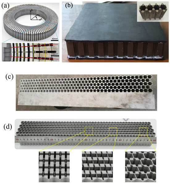
Figure 9.
Acoustic devices processed by wire EDM: (a) acoustic cloak [37], (b) water-like material [38], (c) underwater sound reflection meta-surface [39], and (d) cylindrical wave to plane wave converter [19].
The WEDM technique has higher machining precision compared with the waterjet, and the thickness of the workpiece is not limited. However, the machining efficiency is slow, and it requires extra effort to thread the wire for closed patterns. It also takes a lot of time to finish one piece.
3.4. Additive Manufacturing
The field of additive manufacturing has undergone significant advancements in recent years. Commonly known as rapid prototyping and manufacturing (RPM) or 3D printing, AM is a manufacturing process that constructs objects layer by layer, which stands in stark contrast to subtractive manufacturing, where material is removed from a solid block to achieve the final shape. The versatility of AM is highlighted by its classification into the following seven core categories:
- Stereolithography (SLA): This method uses ultraviolet light to cure and solidify photopolymer resins layer by layer.
- Fused Deposition Modeling (FDM): This method involves the deposition of melted thermoplastic filaments to create an object in a layer-wise manner.
- Selective Laser Sintering (SLS): A laser selectively sinters powdered material to form a solid structure.
- Selective Laser Melting (SLM): In this technique, a high-powered laser fully melts and fuses metallic powders into a solid part.
- Electron Beam Melting (EBM): This method employs an electron beam to melt and fuse metal powder particles layer by layer.
- Digital Light Processing (DLP): A vat of liquid photopolymer is cured layer by layer by a digital light projector.
- Laminated Object Manufacturing (LOM): Layers of material are laminated together and cut to shape using a knife or laser.
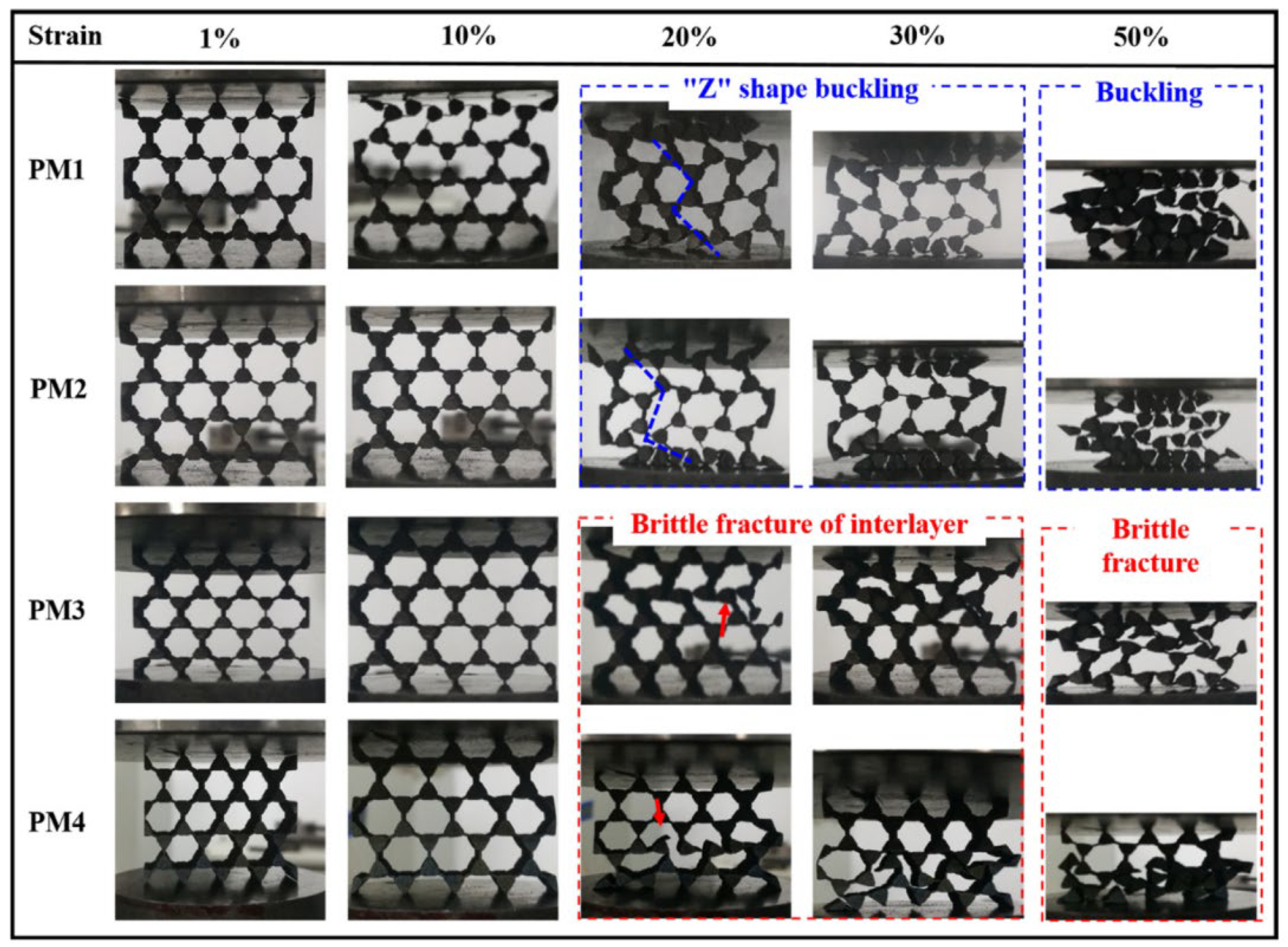
Additive manufacturing is widely used to fabricate complex three-dimensional models that are impossible for other machining methods to create. Three-dimensional PMs are fabricated by dip-in 3D direct laser writing [18,40], 3D printing [41], SLM [42,43], etc. Two-dimensional PMs are mostly fabricated by the SLM method with metal materials. The mechanical properties of the AlSi10Mg alloy fabricated by SLM and casting have been comparatively studied, and some properties were improved by SLM [44]. Zhang et al. [45] utilized SLM to fabricated four types of PMs with different strut widths, named PM1, PM2, PM3, and PM4. The strut widths of PM3 and PM4 were larger than those of PM1 and PM2. Compression testing was conducted on these models. Digital photos of the models at the strain values of 1%, 10%, 30%, and 50% are shown in Figure 10. The results revealed that SLM-manufactured PM structures exhibited dimensional errors, but their elastic properties matched the target characteristics quite well. The experiments showed that, as the strut width increased, the deformation mechanism of the PM structures transitioned from plastic deformation to brittle fracture. This research verified the feasibility of the SLM technique in the fabrication of PM structures and revealed the deformation mechanism of them with different strut widths.
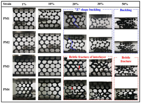
Figure 10.
Compressive deformation process of the four types of PM structures at strain values of 1%, 10%, 20%, 30%, and 50% [45].
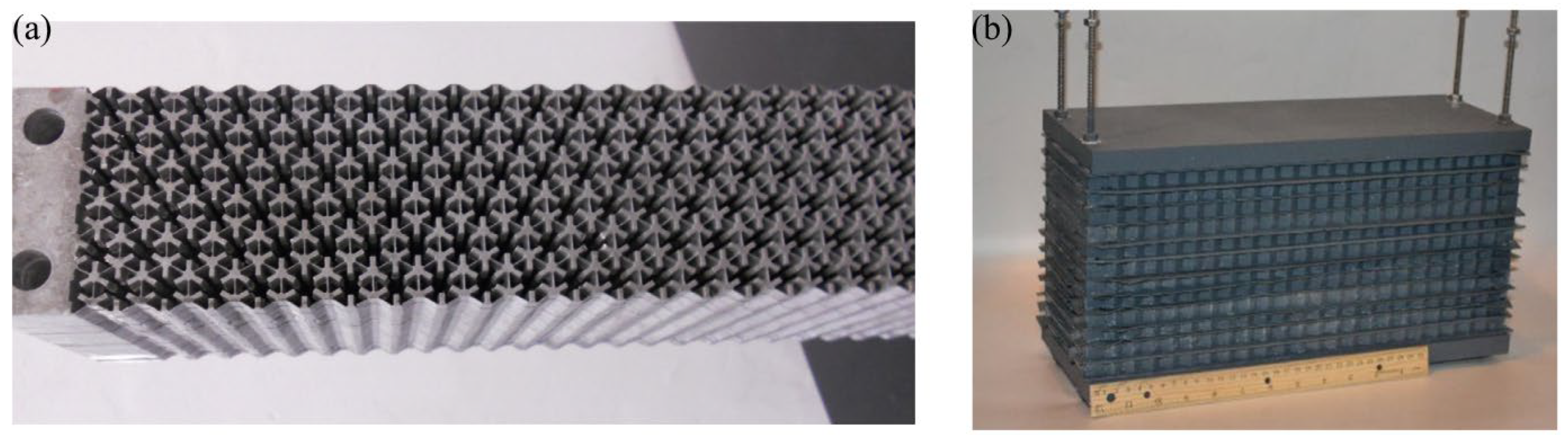
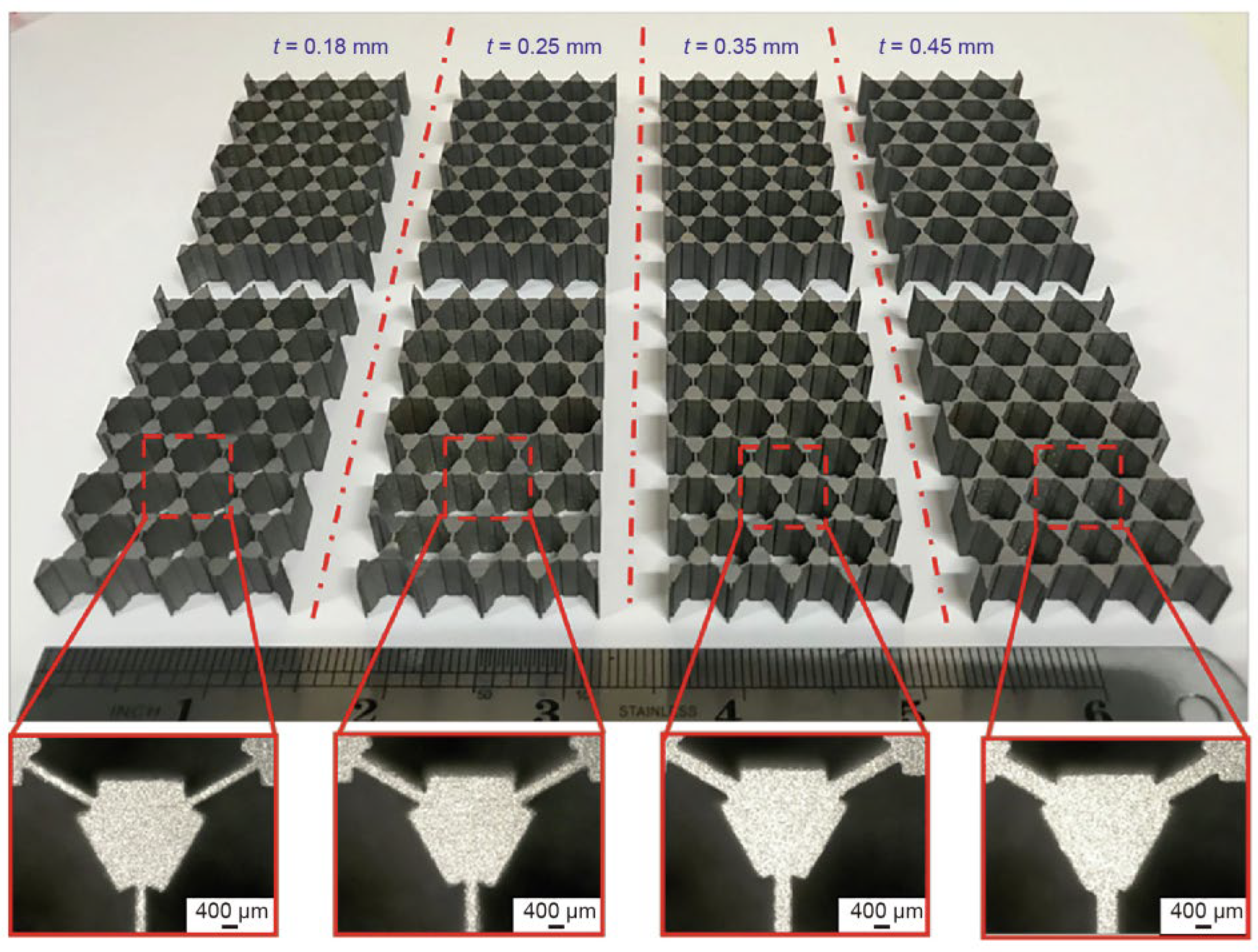
The Poisson’s ratio and compressive modulus of two-dimensional PM structures were also studied for SLM-fabricated models. Zhang et al. [46] fabricated a series of two-dimensional PM structures using the SLM technique with Ti–6Al–4V materials. The samples with different strut widths are shown in Figure 11. The mechanical properties of the PM structures with different strut widths and numbers of layers were investigated. Within a thin strut width range of 0.15 mm to 0.45 mm, the compression modulus of the pentamode structure increased, while the Poisson’s ratio decreased. The stress variations were primarily concentrated at the connection points between the struts and the balancing elements. The different strut widths experienced varying stress levels. Furthermore, the elastic modulus and yield stress of the two-dimensional PM structures were decoupled from their relative density. The obtained compressive modulus values were slightly higher than those of the FE results, and the experimental Poisson’s ratio values were slightly lower than the results of the simulations, resulting from the presence of adhered powder particles.
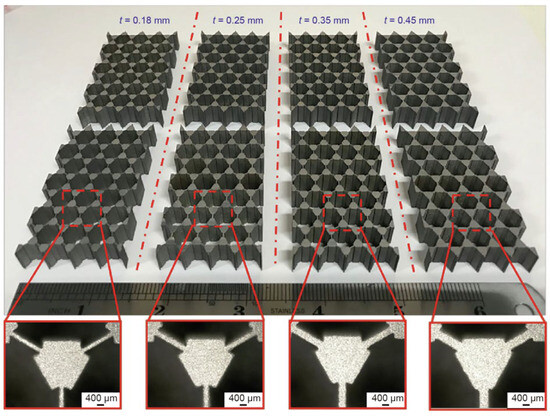
Figure 11.
SLM-built samples of two-dimensional PMs with different sizes [46].
From the existing processing methods, for two-dimensional PM models, techniques such as waterjet cutting, WEDM, and additive manufacturing can be employed for processing. Waterjet cutting offers high efficiency and precision, generally meeting the standard machining requirements; however, it is not suitable for cutting very thick materials. WEDM provides flexibility and has relatively low restrictions on cutting thickness, but the size of the machined samples is limited by the equipment. Additionally, it is associated with higher costs and longer processing times. Additive manufacturing allows the fabrication of complex structures that were previously constrained by traditional manufacturing methods. Nevertheless, it comes with higher manufacturing costs, and the size of the processed samples should not be excessively large, with limitations of the machines. Therefore, further improvements may be needed in the processing of metamaterials with pentamode characteristics.
3.5. Comparison of Different Manufacturing Methods
The four manufacturing methods—micro-milling machining, waterjet cutting, WEDM, and additive manufacturing—are the primary processing methods for two-dimensional PM manufacturing. Each of them has advantages and disadvantages, as listed in Table 1. They should be selected due to the precision requirement, materials, geometry complexity and cost.

Table 1.
Advantages and disadvantages of different manufacturing methods.
4. Applications of Two-Dimensional PMs
PMs only withstand compressional stress within certain frequency ranges. This makes them mimic the properties of fluids. Sometimes, they are named meta-fluid. Their properties depend on their microstructures. Then, amazing devices can be designed by artificially constructed special microstructures arranged periodically. These microstructures, also known as PM units, frequently exhibit exceptional acoustic properties. They can be used to create various acoustic devices with unique properties, such as acoustic cloaks, acoustic lens, acoustic waveguides, etc.
4.1. Fluid-like Materials
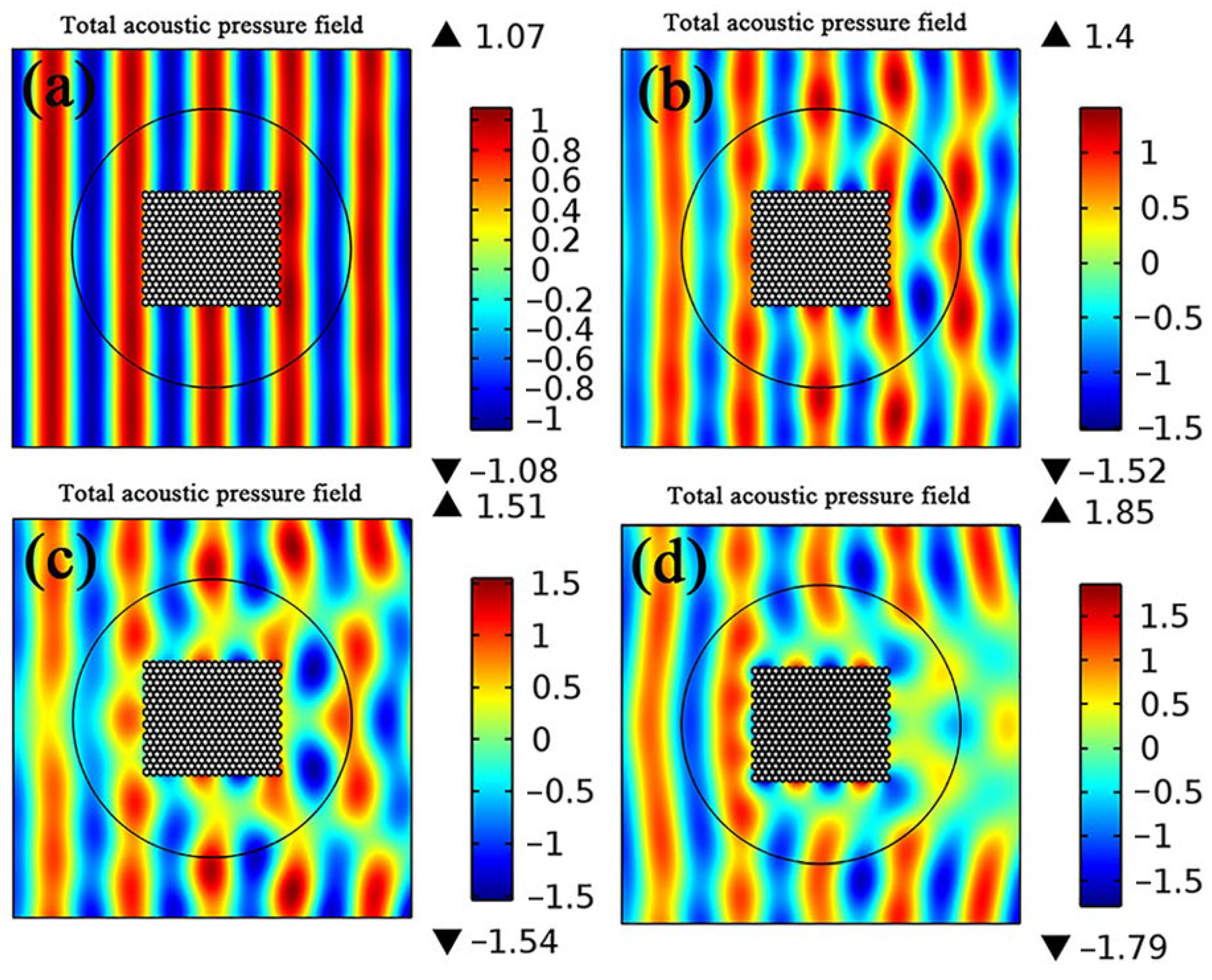
Pentamode materials have fluid-like properties, theoretically. Several models have been designed and simulated to verify this property [29,30,38]. Cai et al. [29] studied the mechanical and acoustic properties of two-dimensional PMs. Four models were designed to approximate the properties of water with unit cells, as shown in Figure 5b. They were named PM1, PM2, PM3, and PM4. Their phase velocities of compressional waves were all 1500 m/s, while the phase velocities of the shear waves varied from 120 m/s to 102 m/s. Their effective densities were all 1000 kg/m3, approximately. Simulations made with the finite element method (FEM) for models composed of the four units were conducted in a background of water, as shown in Figure 12. It was observed that PM1 had almost no effect on the propagation pattern of the acoustic waves in water. However, the scattering in water gradually increased from PM1 to PM4. The acoustic wave frequency was not located in the pentamode band. By analyzing the local vibrations of PM1 to PM4, it was determined that sound wave propagation exhibits the following two modes: the compressional wave mode and the bending mode. The dynamic acoustic properties of PMs are determined by which mode occupies the dominant position. The compressional mode was dominant for PM1, and the bending mode was dominant for PM4. Therefore, in the study of PMs, it is important to not only simplify the conversion of mechanical properties into acoustic properties, but also to consider whether the acoustic wave frequency is located in the pentamode band where only the compressional mode exists.
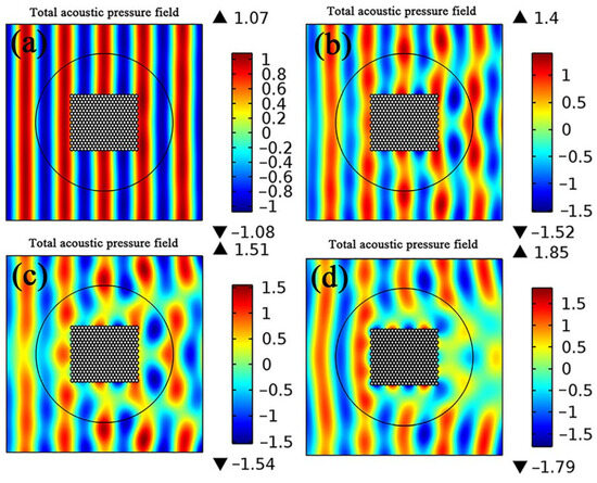
Figure 12.
Simulations of four water-like PMs in water: (a) the total acoustic pressure fields for structures composed of PM1, (b) the total acoustic pressure fields for structures composed of PM2, (c) the total acoustic pressure fields for structures composed of PM3, (d) the total acoustic pressure fields for structures composed of PM4 [29].
PMs with other types of unit cells have also been studied for water-like properties. The structural parameters of unit cells (as Figure 5c shows) were optimized to approximate the properties of water [30]. Simulations with FEM software were conducted to verify the water-like properties, as shown in Figure 13. It was observed that the oblique acoustic wave propagated the area with no effect on the background (as shown in Figure 13a). The simulation of acoustic waves in pure water was conducted for comparison, as shown in Figure 13b. The PMs have a similar acoustic pressure field with water.
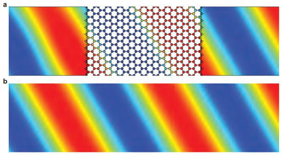
Figure 13.
Simulation of PMs in water with oblique incidence of acoustic waves: (a) simulation of acoustic waves in water with PMs, and (b) simulation of acoustic waves in water for comparison [30].
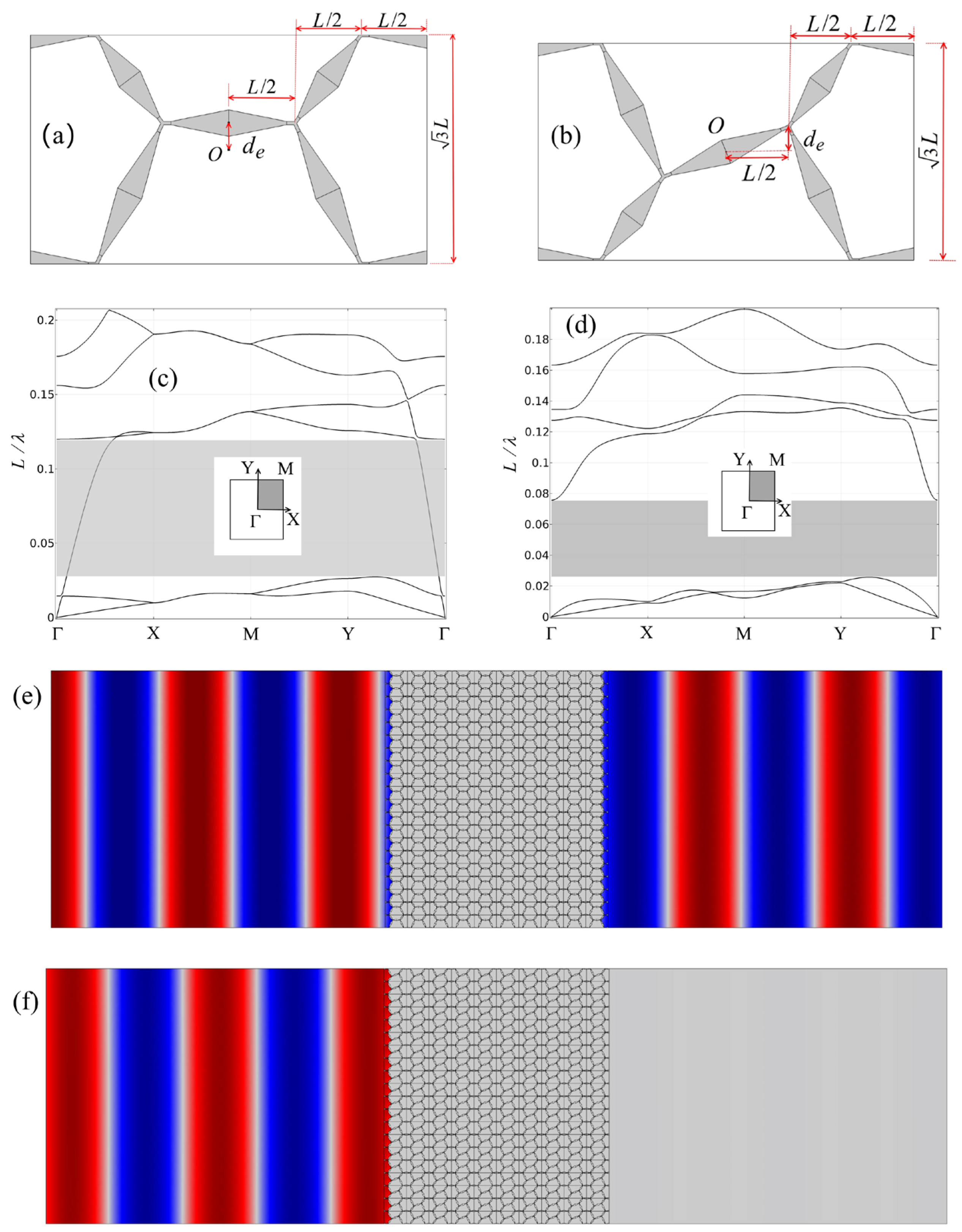
The properties of the PM unit cells are affected by their structural parameters. The dimensions of the arms have been studied. However, the positions of the connection also make a great difference to their effective properties [47]. A rectangular unit cell was also derived for the PMs with the unit cells shown in Figure 2d. There are two connections within the unit cell. If the two connections move upwards or downwards in the same direction, as Figure 14a shows, specific band structures form, which are shown in Figure 14c. There is a frequency range where only the compressional mode exists. The FEM simulation of the materials composed of the unit cell in the background of water is shown in Figure 14e. The vacancy of the unit cells was filled with air in the simulation. The result shows that the PMs have fluid-like properties. The acoustic waves propagate through the material without a loss of energy. The phase is changed due to the difference in the effective velocity. If the two connections move upwards or downwards in opposite directions, as shown in Figure 14b, specific band structures of the unit cell form, which are shown in Figure 14d. There is a total bandgap rather than a pentamode band. The bandgap means that waves cannot propagate in the materials. The simulations of the materials in water also verify this theoretical property.
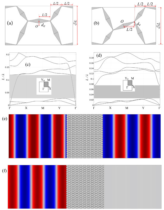
Figure 14.
Unit cells, band structures, and simulations of PMs and bandgap metamaterials: (a) pentamode unit cell, (b) bandgap unit cell, (c) band structures of (a), (d) band structures of (b), (e) simulation of acoustic waves in water with structures composed of (a), and (f) simulation of acoustic waves in water with structures composed of (b) [47].
The special property of PMs is that they can only withstand compressional stress. From the band structures of their unit cells, there is a band where only the compressional mode exists. The effective properties (like density, velocity, etc.) can be altered through the variation of their structural parameters. The PMs can be utilized to mimic fluids. The shear mode, bending mode, and variation of their unit cells also affect the propagation of acoustic waves.
4.2. Acoustic Cloaks
Acoustic cloaks are interesting devices that can hide their enclosed space in an acoustic field. It seems like the acoustic waves travels in a homogeneous medium with no obstacles, if seen from the outside. These cloaks were first proposed in electromagnetics [48], and were introduced to acoustic fields later [49]. Acoustic cloaks can be designed with transformation acoustics, leading to the cloaks having isotropic bulk modulus and anisotropic density. In addition, Norris [24] generalized acoustic cloaks and proposed pentamode acoustic cloaks. Compared with the traditional acoustic cloaks that have anisotropic density and isotropic bulk modulus, pentamode cloaks overcome the dilemma that requires infinite mass density. Thus, pentamode cloaks are more realistic.
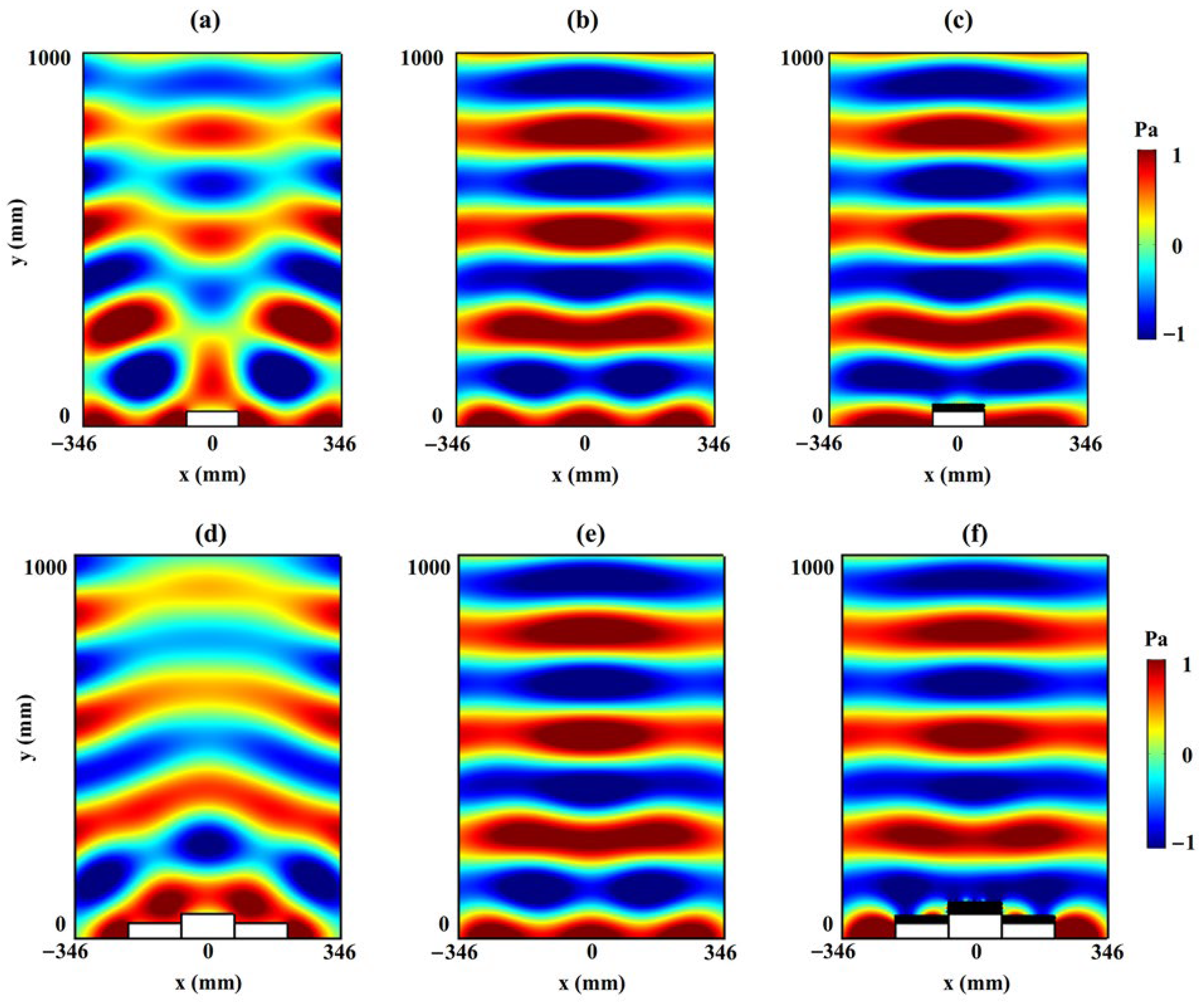
The simplest acoustic cloaks are unidirectional ground cloaks, which only deal with the phase differences in the reflected waves. Layman et al. [28] discussed an acoustic mirage device that can compensate the phase of reflected waves with PMs. With similar principles, Chen et al. [50] designed a broadband underwater carpet cloak based on PMs under normal incidence. The pressure fields of acoustic waves under normal incidence for flat ground, with an uncloaked object and a cloaked object in water, are shown in Figure 15. With the compensation of PMs, the pressure fields of the reflected waves from cloaked objects are almost the same as those from flat ground and are obviously different from those from uncloaked objects.
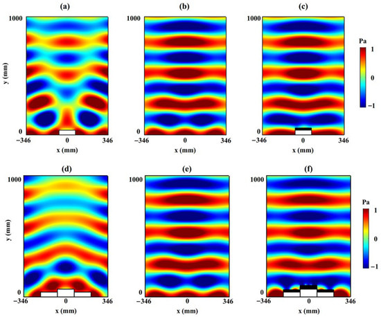
Figure 15.
Acoustic pressure field under normal incidence for an uncloaked object, flat ground, and a cloaked object with unidirectional cloaks: (a,d) present the reflected wave pressure from rectangular objects; (b,e) present the reflected wave pressure from the flat ground for comparison; (c,f) present the reflected wave pressure from the cloaked objects [50].
The cloaked objects of the above cloaks are all rectangles. Ray path analysis with impedance matching on the boundary was also used to design ground cloaks with curved boundaries [51]. Different from the rectangular cloaks, the refraction at the boundaries of the cloaks was considered in the design of these cloaks. Simulations of acoustic waves with normal incidence with and without the cloaks were conducted, as shown in Figure 16. The existence of the cloaks eliminated the scattering. It looks like the acoustic waves were reflected from the flat ground. However, the authors designed acoustic lenses with PMs, and did not discuss the fabrication of the cloaks with PMs.
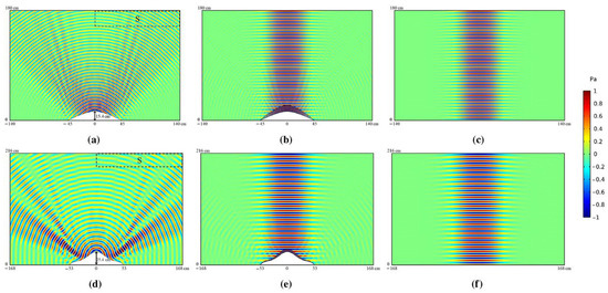
Figure 16.
Acoustic pressure field under normal incidence for an uncloaked object, a cloaked object, and flat ground: (a,d) present the reflected wave pressure from uncloaked objects; (b,e) present the reflected wave pressure from cloaked objects; (c,f) present the reflected wave pressure form flat ground for comparison [51].
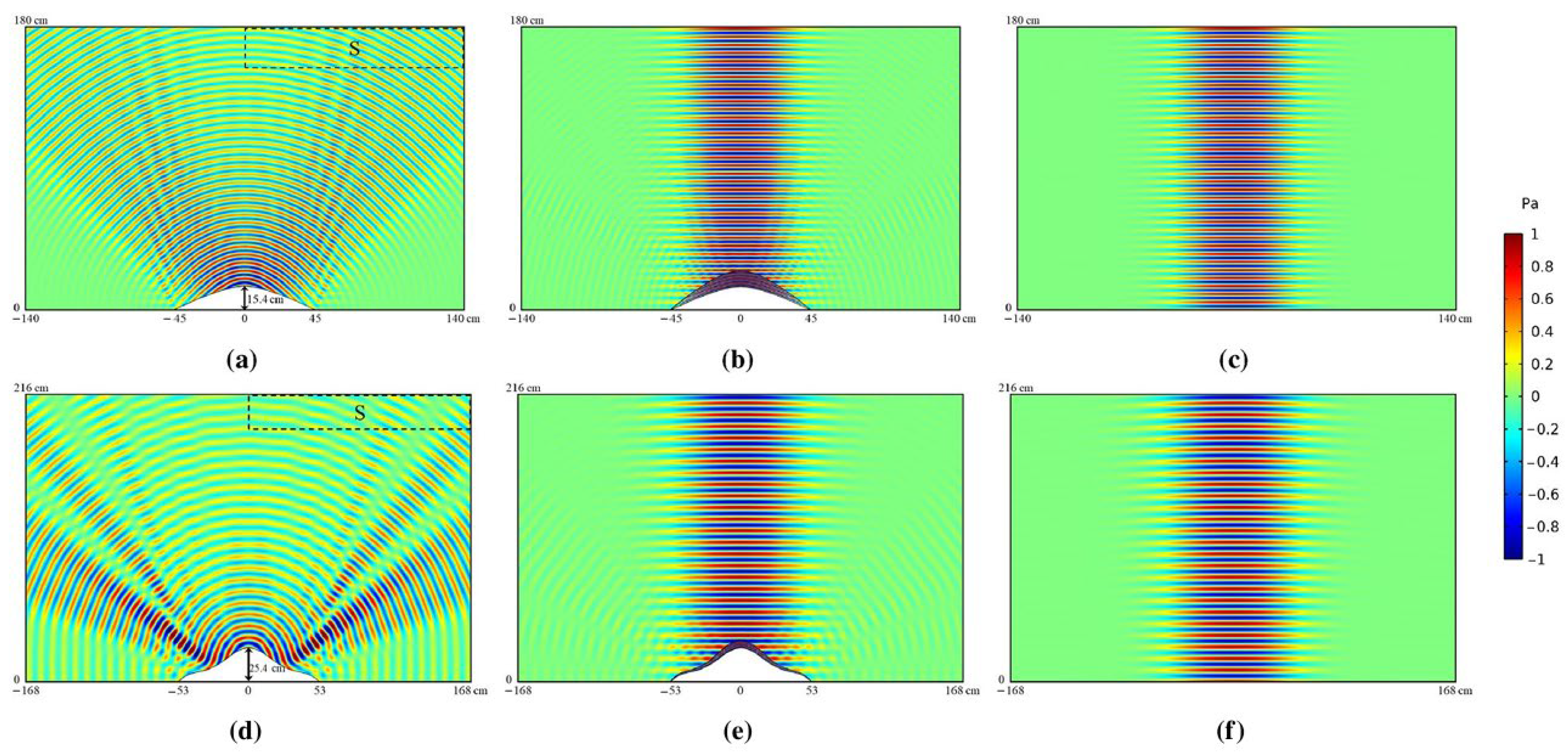
Ground acoustic cloaks, also known as carpet cloaks, are cloaks that can hide enclosed space on the ground. The cloak and its enclosed space work as a flat ground in the acoustic field. Sun et al. [52] designed a ground cloak with two-dimensional PMs. The properties of the acoustic cloak were derived by transformation acoustics by mapping a rectangular area to a ground cape. The cloak was made up of 15 × 20 PM units. The numerical simulations of the ground cloak were conducted with FEM. The results with an oblique incidence of acoustic waves are shown in Figure 17. Figure 17a shows the phenomenon of an incident wave reflected from the ground. The incident wave would be scattered if there was a hump on the ground, as shown in Figure 17b. The scattering would be eliminated if the hump was covered by a theoretical cloak (Figure 17c) or a PM ground cloak (Figure 17d). The results demonstrated nearly perfect cloaking effects over a wide band frequency domain, suggesting potential applications in underwater acoustic detection.
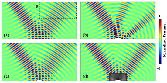
Figure 17.
Performance analysis of the ground acoustic cloak at 15 kHz incident at 55°: (a) acoustic pressure field of the rigid plane, (b) acoustic pressure field of the rigid scatter, (c) acoustic pressure field of the theoretical cloak, and (d) acoustic pressure field of the latticed PM cloak [52].
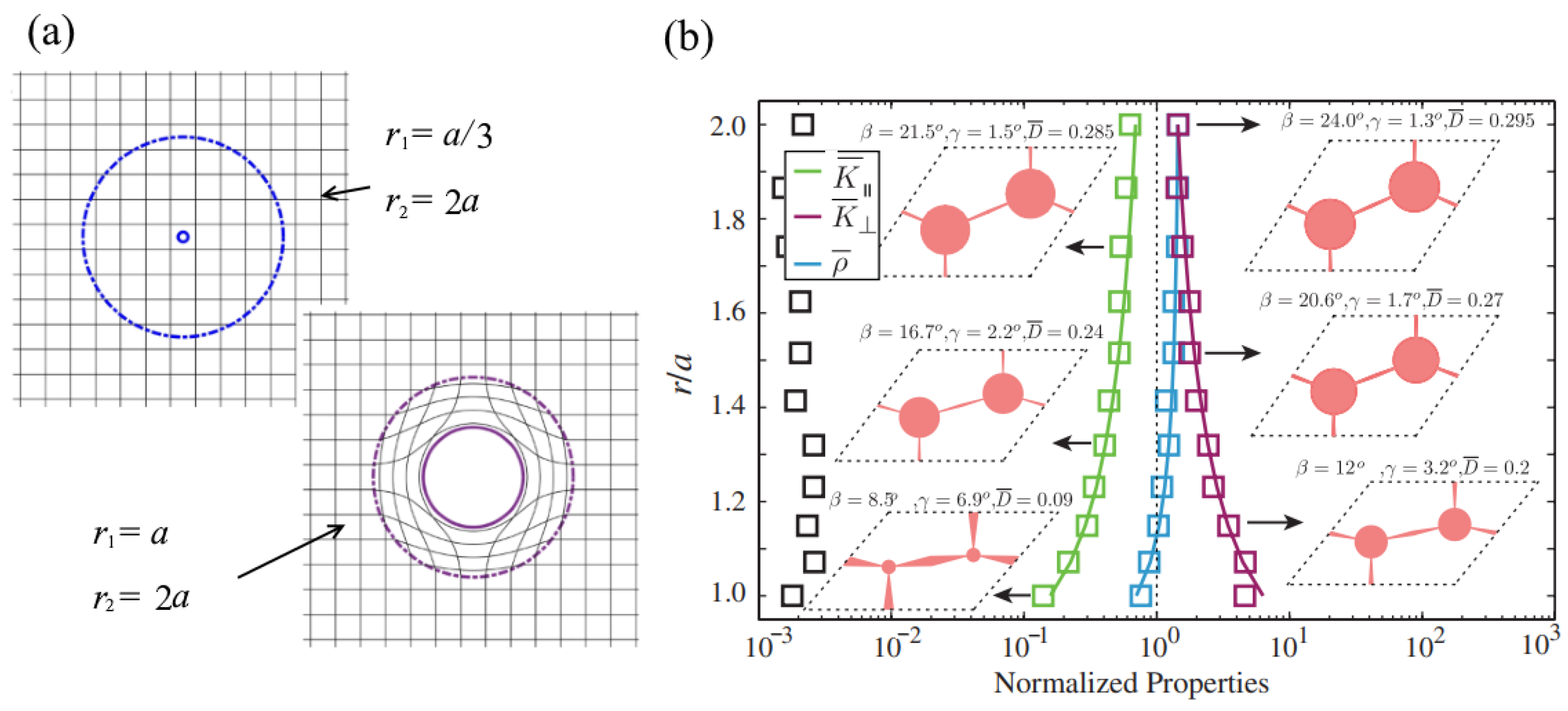
Omnidirectional cloaks are more advantageous because they can hide the enclosed space for waves incident from any direction. The properties of annular cloaks can be derived with the transformation acoustics method. If an acoustic cloak with inner radius a and outer radius 2a is designed by transforming from the virtual space of inner radius a/3 and outer radius 2a (as shown in Figure 18a), specific properties are derived, which are anisotropic and inhomogeneous. The properties can be used to guide the design of the pentamode unit cells. The solid lines in Figure 18b indicate the theoretical properties of the cloak. The unit cells with equivalent properties approximating the theoretical properties of acoustic cloaks were designed, as shown in Figure 18b, in which the squares indicate the promising applications of the materials in the fabrication of acoustic cloaks [28].
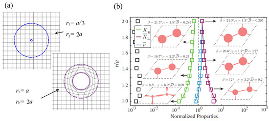
Figure 18.
Design of acoustic cloaks with PMs: (a) design of acoustic cloaks with transformation acoustics and (b) properties of the unit cells to approximate the properties of the cloak [28].
The annular pentamode cloak was finally designed and simulated by Chen et al. [31] in 2015. The theoretical properties were designed with the transformation acoustics shown in Figure 19a, with the solid lines. The discrete approximation of the cloak was obtained by taking a series of values at different positions and adjusting the equivalent properties of the units based on the properties of the different layers. The effective properties of the unit cells are shown in Figure 19a with the dotted lines. With these unit cells, the acoustic cloak with layers of pentamode unit cells was developed, as shown in Figure 19b. The numerical simulations with the FEM software COMSOL Multiphysics were conducted on a water background containing an obstacle both without and with the cloak. The performance of the acoustic waves at two frequencies is shown in Figure 19c. Without the cloak, the cylindrical obstacle reflected the sound waves, resulting in reflections in front and a shadow behind it. However, when the cloak was placed around the cylinder, both reflections and shadows significantly reduced, achieving invisibility in the acoustic field.
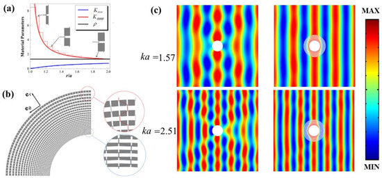
Figure 19.
Design and simulation of two-dimensional annular cloak: (a) pentamode unit cells to approximate the properties of the cloak, (b) the structures of the cloak, and (c) performance of the cloaks in two frequencies [31].
4.3. Acoustic Lens
Just like the effect of an optical lens on light, an acoustic lens can manipulate acoustic waves in many ways. Acoustic lenses can be designed in different ways. Due to the tuning of effective properties, PMs can be used to design different kinds of acoustic lenses. They can focus acoustic waves, change the direction of wave fronts, transform cylindrical waves into plane waves, etc.
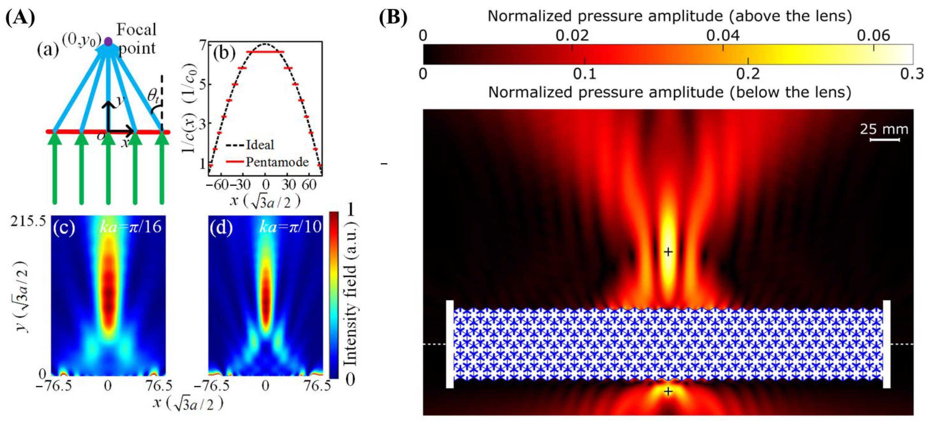
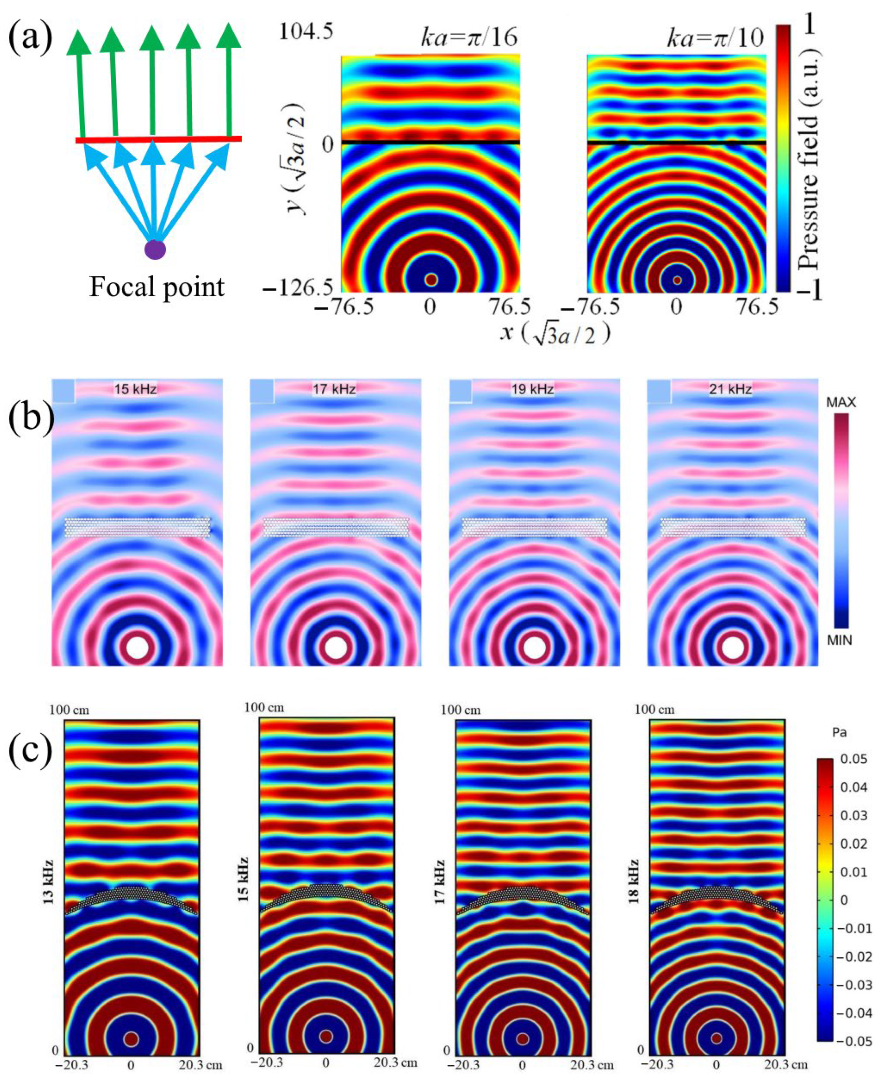
In optics, light can be converged by a convex lens and diverged by a concave lens. Acoustic waves can also be focused by a delicately designed acoustic lens. Tian et al. [53] designed an acoustic meta-surface that could focus acoustic waves. A schematic of the effect of the meta-surface is shown in Figure 20A(a). Acoustic waves were focused on the focal point by the meta-surface. To design this lens, a series of pentamode unit cells with different acoustic velocities were designed and placed delicately, as shown in Figure 20A(b). Simulations with FEM software were conducted to verify the effect of the acoustic meta-surface. The results in two frequencies are shown in Figure 20A(c,d). The meta-surface had obvious effects on focusing the acoustic waves. In addition to this method, Hladky-Hennion et al. [22] designed an acoustic flat lens for focusing acoustic waves via the negative refraction of PMs. The negative index property arose from an isolated branch of the dispersion curves corresponding to a mode that could be coupled to incident acoustic waves in the surrounding water. An aluminum model was fabricated, and the researchers experimentally verified its performance in focusing acoustic waves, as shown in Figure 20B, in which the aluminum model is shown in blue. The source emitting the cylindrical waves at 71.2 kHz was located below the lens, and the focusing effect was observed above. The locations of the source and those of the focus point are shown as black crosses. It can be seen that the acoustic waves emitted from the source on one side focused on a point at the other side. However, it should be noted that different colored maps are shown below and above the slab. The loss of acoustic energy was high, which may be due to the poor impedance matching of the lens with water.
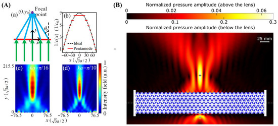
Figure 20.
Acoustic lenses for focusing acoustic energy: (A) acoustic meta-surface with graded refractive indices (a) Schematic of acoustic sub-wavelength flat lens with a focal point (0, y0), (b) The reciprocal of the velocity distributions for the ideal meta-surface (black dashed line) and pentamode meta-surface (red solid line), (c) Intensity field distribution of the flat lens under plane incidence at ka ~ π/16, (d) Intensity field distribution of the flat lens under plane incidence at ka ~ π/10 [53] and (B) acoustic lens with negative refraction [22].
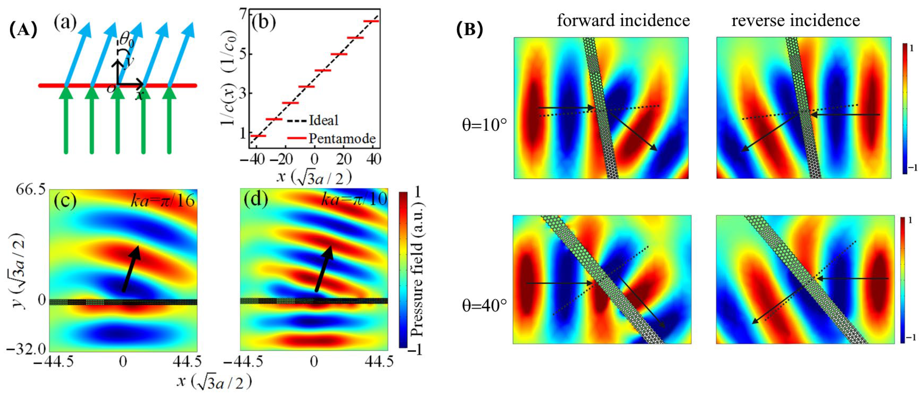
PMs can be used to design acoustic lenses that can change the propagation of acoustic waves. Tian et al. [53] designed an acoustic meta-surface that caused the anomalous refraction of acoustic waves with PMs. A schematic of the performance of the meta-surface is shown in Figure 21A(a). The incident waves (denoted in green) were refracted (denoted in blue) by the meta-surface placed normal to the incident waves. To design the meta-surface, a series of unit cells with gradient refractive indices were developed, as shown in Figure 21A(b). The properties of the unit cells (red solid lines) were utilized to approximate the theoretical properties (black dashed lines). When the designed pentamode meta-surface was placed in the acoustic field and sound waves were applied from the bottom edge at certain frequencies, specific sound fields were observed, which are illustrated in Figure 21A(c,d). The pentamode meta-surface effectively deflected the sound waves, and the black arrows show the theoretical direction of the refractive waves. The effect of the meta-surface closely matched the theoretical properties and had broadband characteristics. Chu et al. [21] designed a pentamode meta-surface for two-dimensional PMs, which exhibited broadband, efficient, and controllable asymmetric transmission characteristics for sound waves, as shown in Figure 21B. It was observed that positive refraction occurred for the forward incidence, while negative refraction occurred for the backward incidence when the incident angle equaled 10°. Subsequent research showed that the meta-surface could achieve sound asymmetric transmission over a wide frequency range of 2600 to 5600 Hz, with a transmittance of over 85.4%. When the incident angle was 40°, positive refraction occurred for the forward incidence, and the transmitted wave for the forward incidence propagated along the meta-surface. The acoustic wave can be converted from a propagating wave to a surface wave through the meta-surface. This research on asymmetric sound transmission provides new insights for the study of controlling acoustic waves.

Figure 21.
Manipulation the propagating direction of acoustic waves: (A) sub-wavelength flat lens (a) Schematic of anomalous refraction. Green arrows denote plane waves with normal incidence, while blue arrows denote refracted waves. (b) The reciprocal of the velocity distributions for the ideal meta-surface (black dashed line) and pentamode meta-surface (red solid line). (c) or (d) Pressure field distribution of the PM meta-surface at ka ~ π/16 or π/10. The black arrows refer to the theoretical direction of refraction [53]. (B) Simulated acoustic pressure fields for forward incidence and reverse incidence of 10° and 40° [21].
Cylindrical acoustic waves can be transformed into plane waves with acoustic lenses built with PMs. Tian et al. [53] reversed the use of the focusing lens, as shown in Figure 20A. If a point source is in the focal point of the lens, the cylindrical waves emitted from the source should be transformed into plane waves after passing through the flat lens. Simulations with the FEM software were conducted at different frequencies. The schematics and simulation results are shown in Figure 22a. The meta-surface successfully transformed the cylindrical waves into plane waves. Similar designs were also proposed by Chen and Hu [19]. The performance of the lens when transforming cylindrical waves into plane waves at frequencies of 15 kHz, 17 kHz, 19 kHz, and 21 kHz are shown in Figure 22b. The designed meta-surface was fabricated (shown in Figure 9d) and tested under transient cylindrical wave incidence conditions in a two-dimensional underwater sound waveguide. The experimental results matched well with the numerical simulation results, and the manufacturing cost was relatively low. This provides new opportunities for practical applications in low-frequency underwater acoustic measurements. Furthermore, Eslamzadeh et al. [51] designed a fan-shaped PM lens with the ray path method. The lower boundary of the lens was a circular arc with the source on the center of the circular sector, and the acoustic impedance of the PMs matched with that of water. The thickness of the lens compensated for the phase difference from a cylindrical wave to a plane wave, and the results show that the designed pentamode lens successfully converted the cylindrical waves into plane waves. A unique advantage of the lens is that it is composed of a single unit-cell instead of a series of different unit cells. According to the reciprocal theory, the reverse scenario would be a lens that focuses the incident plane waves on the focal point.

Figure 22.
Simulations of acoustic lenses transforming cylindrical waves into plane waves: (a) pressure field distribution of the flat lens under cylindrical incidence emitted from a point source located at a focal point with ka ~ π/16 or π/10 [53], (b) Simulated pressure fields with PM me-ta-surface corresponding to 15 kHz, 17 kHz, 19 kHz and 21 kHz, respectively [19], (c) the acoustic pressure fields for the designed pentamode lens using elaborated carpet cloak strategy [51].
Other kinds of acoustic lenses can also be constructed with PMs. PMs can only withstand compressional stresses within a certain range of frequencies, and their effective properties can be tailored by the dimensions and structures. Therefore, they are ideal materials to design acoustic lenses.
4.4. Acoustic Waveguide
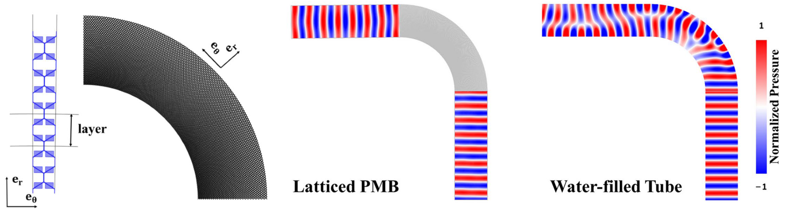
PMs can be utilized to design acoustic waveguides that guide the propagation of the acoustic waves. Sun et al. [20] designed a bend-shaped acoustic waveguide composed of PMs. To keep the nice bending effect and high transmission rate, the phase of the wave did not vary along the radial direction and all of the energy of the incident wave was able to pass through the bend. They calculated the properties of the waveguide theoretically and designed a two-dimensional phononic crystal model based on the required properties, as shown on the left of Figure 23. With unit cells of different geometric parameters moving from the inside to the outside, they created the entire waveguide structure along the tangential array. When the sound waves were incident from the bottom into a curved water-filled pipe, the waves ceased to be plane waves after passing through the bend. However, when the waveguide was placed in the acoustic field, the sound waves incident from the bottom still maintained a plane wave shape after passing through the bend. The simulation results are shown on the right of Figure 23.

Figure 23.
Microstructures and performance analysis of the acoustic waveguide [20].
Chen et al. [54] designed and fabricated an underwater bend acoustic waveguide with anisotropic density. The waveguide was discretized into four different layers with inclination angles of 25° and 50°. The fabricated waveguide with an inclination angle of 25° is shown in Figure 24A. The experimental setup in water is shown in Figure 24B. The simulated and measured pressure fields at 20 kHz for the free space and the anisotropic-density waveguide are shown in Figure 24C,D. The research has revealed that anisotropic-density waveguides maintained a high transmission efficiency in the frequency range of 20–40 kHz, with an average transmission coefficient of above 0.8. However, these two anisotropic-modulus waveguides were not as good as the former ones in the frequency band of 30–40 Hz, and the transmission rate in the high frequency band of 36–40 kHz dropped significantly. Consequently, acoustic waveguides with anisotropic density can provide a broader control over underwater acoustics across a wider frequency band.
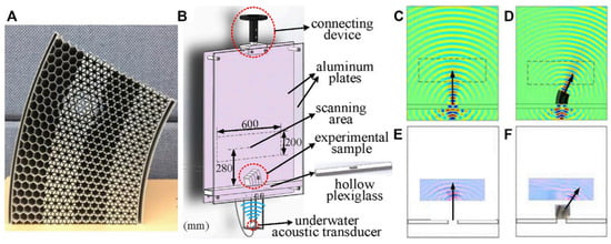
Figure 24.
Performance analysis of the acoustic waveguide: (A) The experimental sample of the acoustic waveguide with anisotropy density and a thickness of 50 mm; (B) two-dimensional underwater acoustic waveguide experimental device. The length, width and thickness of two parallel aluminum plates are 1000, 800 and 10 mm, respectively, and the distance between the two plates is 50 mm. The part enclosed by the black dotted line is the acoustic field scanning area, its length and width are 600 and 200 mm respectively, and its geometric center is 280 mm away from the bottom of the sample; (C) Pressure map of the free space simulated at 20 kHz; (D) Pressure map of the acoustic waveguide with anisotropy- density simulated at 20 kHz; (E) Measured pressure of the free space at 20 kHz; (F) Measured pressure of the anisotropy-density acoustic waveguide at 20 kHz [54].
4.5. Underwater Acoustics
Two-dimensional PMs have intriguing properties that could greatly enhance underwater communication systems. The following is a detailed elaboration of their potential impact:
Signal Clarity and Propagation: Traditional materials may not effectively channel sound waves, resulting in signal loss and degradation over distances. Pentamode metamaterials can be designed with specific microstructural configurations that closely mimic the acoustic properties of water. This tailored design allows sound waves to propagate with minimal scattering and absorption, maintaining signal integrity over greater distances than conventional materials allow [55].
Customizable Acoustic Properties: The acoustic properties of PMs, such as their effective density and modulus, can be engineered to match or contrast the surrounding medium. By creating a match, they can reduce the reflections and refractions that normally occur at the material boundaries. For divergent properties, they can steer or focus sound waves as needed, which is advantageous for directed communication channels in noisy underwater environments.
Improved Underwater Stealth and Surveillance: In military and surveillance applications, controlling the acoustic signature is crucial. Two-dimensional PMs can be used to cloak submarines or underwater drones, making them nearly invisible to sonar detection. By guiding sound waves around objects, these materials can reduce the acoustic shadow and reflected waves that typically give away a vessel’s location.
Enhanced Deep-Sea Exploration: For deep-sea exploration, maintaining communication with remote vehicles or instruments is critical. The use of PMs in the design of underwater antennas or signal enhancers could improve the reliability of data transmission from great depths, allowing for more ambitious exploration missions.
Mitigating Signal Dispersion: High-frequency underwater signals often suffer from dispersion, where different frequencies travel at different speeds, distorting the signal over a distance. Two-dimensional PMs can be engineered to have dispersion relations that counteract this effect, preserving the coherence of the communication signals, even in the deep ocean.
Design of Acoustic Channels: Similar to fiber optics in telecommunications, two-dimensional PMs could be used to create ‘acoustic waveguides’. These structures could channel sound waves efficiently over long distances without the side lobes and scattering that typically occur in complex underwater environments.
4.6. Medical Ultrasound
Two-dimensional PMs possess unique acoustic properties that can be harnessed to significantly enhance the precision of medical ultrasound devices. The following outlines how they could lead to advancements in diagnostic imaging and treatment:
The design of two-dimensional PMs allows efficient manipulation of the acoustic wavefront under broadband conditions. By precisely tuning the bulk modulus and effective density of each unit, these PMs not only achieve high transmittance but also enable precise manipulation of the acoustic wavefront. This manipulation technique is particularly valuable in the field of medical ultrasound imaging because it can significantly improve the quality and resolution of imaging [56]. By carefully designing the microstructure of pentamode metamaterials to control acoustic waves, engineers can create lenses or interfaces that focus ultrasound waves more accurately. This can lead to sharper imaging with better resolution, allowing for the early detection of medical conditions that might be missed by traditional ultrasound technology.
By utilizing meta-surfaces constructed from two-dimensional PMs, a structure capable of converting plane waves into circular bottle-shaped beams can be designed. This structure has potential applications in biomedical imaging and in vivo cell manipulation [57].
By adjusting the geometric parameters of the microstructure through two-dimensional pentamode metamaterials, acoustic lenses can be designed and optimized to achieve efficient acoustic focusing in underwater environments. Additionally, this lens design minimizes the shear modulus, which is very advantageous for acoustic designs since shear modulus often diminish acoustic wave strength in acoustic applications. With this design, the lens is able to focus sound waves to a very small focal point with almost no side lobes, which is extremely important for medical imaging because it can improve the resolution and quality of imaging [36].
By enhancing the precision and capabilities of medical ultrasound, PMs could lead to better patient outcomes through a more accurate diagnosis, non-invasive treatments, and personalized medicine approaches.
4.7. Practical Considerations in Device Fabrication
The pentamode behavior of metamaterials is inherently tied to their structural dimensions, particularly the scale of their microstructures relative to the wavelength of the sound waves that they are designed to manipulate. The following outlines an in-depth discussion on this dependency and its implications for real-world applications:
Device Dimensions Relative to Wavelength: The key to the practical use of PMs is the scaling of the device features relative to the wavelength of sound in the material. It is crucial to ensure that the microstructure dimensions of the metamaterial are significantly smaller than the wavelength in order to achieve the desired metamaterial properties. This enables the effective manipulation of the sound waves and ensures that the device operates within the designed pentamode band.
Frequency Range and Structural Dimensions: In PMs, the effective medium theory applies when the feature size of the metamaterial is much smaller than that of the acoustic wavelength. The pentamode behavior—where the material behaves like an ideal fluid that supports compressional waves but not shear waves—is critically dependent on the ratio of the structural dimensions to the wavelength. For a given material, the size of the unit cells and, by extension, the struts and joints that compose these cells, must be small enough so that the incoming wave does not resolve the individual structures, ensuring that the wave interacts with the metamaterial as if it were a homogeneous medium [58].
Challenges in Fabrication: As the device size increases to accommodate low-frequency applications, the fabrication becomes more challenging. Manufacturing large, intricate structures while maintaining precise microscale features over macroscopic distances requires advanced fabrication methods and can increase the cost and complexity of production [59].
In conclusion, the structural dimensions of PMs determine the operational frequency range and significantly impact the design and feasibility of devices across various applications. The requirement of larger structures at lower frequencies necessitates the careful consideration of manufacturing capabilities and cost implications, while, for higher frequencies, the emphasis is on precision and the miniaturization of structures.
5. State of Art
5.1. Recent Academic Research
- Additive manufacturing technology of hybrid anisotropic PMs: This study presents various anisotropic lattices of PMs constructed using additive manufacturing technology and analyzes their elastic properties. This study demonstrates the potential of using additive manufacturing technology to design and construct composite materials with arbitrary elastic tensor eigenvalues.
- Topological design and additive manufacturing of PMs: A new generative design method is proposed to find new micro-lattice architectures using topology optimization to realize PMs [34]. This study demonstrates the capability of additive manufacturing technology in producing solid structures with fluid properties.
- Design and simulation of broadband multiphase PMs: This study proposed a PM cell for controlling underwater waves and proposed the concepts of two-phase and three-phase PMs [60]. This shows that adding the second and third phases not only broadens the range of the achievable properties of PMs, but also suppresses the undesired vibration modes, showing the broadband properties of multiphase PMs.
- Mechanical metamaterials: a state of the art: This comprehensive review article delves into the advancements in mechanical metamaterials, exploring their design principles, fabrication techniques, and applications. It highlights significant developments in the field and outlines future research directions [61].
- Experimental and Theoretical Study of the Elastic Properties of PMs: This investigation by Kadic et al. [40] explores the elastic properties of PMs through experimental and theoretical lenses. The results not only validate previous theoretical models but also open avenues for applications in controlling mechanical and acoustic wave propagation.
- Mechanical Metamaterials and Their Engineering Applications: Li, Z. et al. [62] examine the practical engineering applications of mechanical metamaterials, focusing on their utility in sectors such as vibration control and aerospace. Their work demonstrates the adaptability of metamaterials to meet specific industrial needs through customized designs.
These studies collectively expand our understanding of metamaterials, highlighting their theoretical and practical significance across a spectrum of scientific and engineering contexts. Each piece of research contributes uniquely to the mosaic of knowledge that supports the ongoing development and application of innovative metamaterial designs. The summary of the properties, materials, manufacturing methods, and applications are shown in Table 2.
Table 2.
Summary of properties, materials, manufacturing methods and applications of two-dimensional PMs.
5.2. Application Outlook
- Acoustic Cloaking and Manipulation: The unique properties of PMs give them great potential in the fields of acoustic cloaking and sonic manipulation. By designing specific microstructures, the precise control of sound waves can be achieved, such as guiding, absorbing, and reflecting sound waves to achieve stealth or improve acoustic performance.
- Mechanical Protection and Impact Absorption: The customized design of two-dimensional PMs also shows unprecedented potential in mechanical protection and impact absorption applications. These materials can exhibit extremely high stiffness in specific directions while providing high flexibility and energy-absorbing capabilities in other directions, making them suitable for use in earthquake-resistant construction, sports equipment, and vehicle protection.
- Biomedical Engineering: The combination of the tunable elastic properties of PMs and biocompatible materials provides new ideas for biomedical engineering, especially for the development of implantable medical devices. For example, the mechanical properties of implants can be tailored to a patient’s specific medical needs to promote better biointegration and functional recovery.
These latest academic results and potential applications demonstrate the broad application prospects of two-dimensional PMs in multiple cutting-edge scientific and technological fields, providing rich inspiration and direction for future material science and engineering research.
6. Conclusions
Pentamode metamaterials, as a subset of acoustic metamaterials, exhibit unique characteristics that prevent the propagation of shear waves within a certain frequency range. Their structure, typically composed of interconnected arm structures, is pivotal in determining their pentamode frequency band and equivalent cell properties. Various factors, including their cell type, arm type, arm symmetry, arm composite structure, and the connection point position, play significant roles. Notably, pentamode metamaterials can achieve anisotropic properties that are challenging to obtain with fluid materials, lending them to applications such as the design of low-frequency, broadband, and omnidirectional underwater stealth devices, as well as the construction of meta-surfaces for asymmetric transmission characteristics and elbow-type waveguides.
Recent advancements in additive manufacturing have further expanded the potential of pentamode metamaterials. Studies such as the additive manufacturing of hybrid anisotropic pentamode metamaterials, the topological design and additive manufacturing of pentamode metamaterials, and the design and simulation of broadband multiphase pentamode metamaterials highlight the innovative approaches to creating these materials with enhanced precision and properties. These advances demonstrate the feasibility of using additive manufacturing to fabricate composite materials with arbitrary elastic tensor eigenvalues, producing solid structures with fluid-like properties, and extending the property range of pentamode metamaterials through multiphase designs.
The application outlook for pentamode metamaterials is broad and promising, spanning from acoustic cloaking and manipulation to mechanical protection, impact absorption, and even biomedical engineering. The ability to design specific microstructures for the precise control of sound waves opens new avenues in stealth technology and acoustic performance enhancement. Additionally, the tailored mechanical properties facilitated by the unique design of two-dimensional pentamode metamaterials make them suitable for a wide range of applications, including earthquake-resistant structures, sports equipment, and vehicle protection. In biomedical engineering, the combination of tunable elastic properties with biocompatible materials offers novel solutions for implantable medical devices, potentially improving patient outcomes through better biointegration and functional recovery.
Given the complex structure of pentamode metamaterial units and the challenges associated with their large-scale production, processing remains a key issue. While specialized processing methods like waterjet processing, EDM wire cutting, and particularly additive manufacturing have been utilized, the quest for rapid, high-precision, and large-size microstructure fabrication continues to drive research and development in this field.
In summary, the unique characteristics and growing capabilities of pentamode metamaterials forecast their increasing utilization across diverse applications. As the technology progresses, the integration of innovative manufacturing techniques and the exploration of new application domains will likely propel pentamode metamaterials to the forefront of material science and engineering research.
Author Contributions
Investigation, C.Z., X.S., Z.X. and H.Y.; writing—original draft preparation, C.Z.; writing—review and editing, Q.L.; project administration, Q.L.; funding acquisition, Q.L. All authors have read and agreed to the published version of the manuscript.
Funding
This research was funded by the National Natural Science Foundation of China (grant number 52001046), and the Fundamental Research Funds for the Central Universities (grant number 3132024114).
Data Availability Statement
The data that support the findings of this study are available from the corresponding author, upon reasonable request.
Conflicts of Interest
The authors declare no conflicts of interest.
References
- Walser, R.M. Metamaterials: What Are They? What Are They Good for? In Proceedings of the APS March Meeting Abstracts, Minneapolis, MN, USA, 20–24 March 2000. [Google Scholar]
- Walser, R.M. Electromagnetic Metamaterials. In Complex Mediums II: Beyond Linear Isotropic Dielectrics; SPIE: Bellingham, WA, USA, 2001; Volume 4467, pp. 1–15. [Google Scholar]
- Ding, C.-L.; Dong, Y.-B.; Zhao, X.-P. Research advances in acoustic metamaterials and metasurface. Acta Phys. Sin. 2018, 67, 194301. [Google Scholar] [CrossRef]
- Zhou, J.; Li, L. Metamaterial Technology and Its Application Prospects. Chin. J. Eng. Sci. 2018, 20, 69. [Google Scholar] [CrossRef]
- Lee, D.; Nguyen, D.M.; Rho, J. Acoustic Wave Science Realized by Metamaterials. Nano Converg. 2017, 4, 3. [Google Scholar] [CrossRef]
- Cummer, S.A.; Christensen, J.; Alù, A. Controlling Sound with Acoustic Metamaterials. Nat. Rev. Mater. 2016, 1, 16001. [Google Scholar] [CrossRef]
- Cai, C.; Han, C.; Wu, J.; Wang, Z.; Zhang, Q. Tuning Method of Phononic Band Gaps of Locally Resonant Pentamode Metamaterials. J. Phys. D Appl. Phys. 2019, 52, 045601. [Google Scholar] [CrossRef]
- Zheng, Y.; Dai, H.; Wu, J.; Zhou, C.; Wang, Z.; Zhou, R.; Li, W. Research Progress and Development Trend of Smart Metamaterials. Front. Phys. 2022, 10, 1069722. [Google Scholar] [CrossRef]
- Mousanezhad, D.; Babaee, S.; Ghosh, R.; Mahdi, E.; Bertoldi, K.; Vaziri, A. Honeycomb Phononic Crystals with Self-Similar Hierarchy. Phys. Rev. B 2015, 92, 104304. [Google Scholar] [CrossRef]
- Wang, H.; Zhang, L.; Shah, S.; Zhu, R.; Zheng, B. Homogeneous Material Based Acoustic Concentrators and Rotators with Linear Coordinate Transformation. Sci. Rep. 2021, 11, 11531. [Google Scholar] [CrossRef]
- Zhu, W.; Ding, C.; Zhao, X. A Numerical Method for Designing Acoustic Cloak with Homogeneous Metamaterials. Appl. Phys. Lett. 2010, 97, 131902. [Google Scholar] [CrossRef]
- García-Chocano, V.M.; Sanchis, L.; Díaz-Rubio, A.; Martínez-Pastor, J.; Cervera, F.; Llopis-Pontiveros, R.; Sánchez-Dehesa, J. Acoustic Cloak for Airborne Sound by Inverse Design. Appl. Phys. Lett. 2011, 99, 074102. [Google Scholar] [CrossRef]
- Zhang, S.; Xia, C.; Fang, N. Broadband Acoustic Cloak for Ultrasound Waves. Phys. Rev. Lett. 2011, 106, 024301. [Google Scholar] [CrossRef] [PubMed]
- Zigoneanu, L.; Popa, B.-I.; Cummer, S.A. Three-Dimensional Broadband Omnidirectional Acoustic Ground Cloak. Nat. Mater. 2014, 13, 352–355. [Google Scholar] [CrossRef]
- Zigoneanu, L.; Popa, B.-I.; Starr, A.F.; Cummer, S.A. Design and Measurements of a Broadband Two-Dimensional Acoustic Metamaterial with Anisotropic Effective Mass Density. J. Appl. Phys. 2011, 109, 054906. [Google Scholar] [CrossRef]
- Zhao, J.; Chen, Z.N.; Li, B.; Qiu, C.-W. Acoustic Cloaking by Extraordinary Sound Transmission. J. Appl. Phys. 2015, 117, 214507. [Google Scholar] [CrossRef]
- Brun, M.; Guenneau, S.; Movchan, A.B. Achieving Control of In-Plane Elastic Waves. Appl. Phys. Lett. 2009, 94, 061903. [Google Scholar] [CrossRef]
- Bückmann, T.; Thiel, M.; Kadic, M.; Schittny, R.; Wegener, M. An Elasto-Mechanical Unfeelability Cloak Made of Pentamode Metamaterials. Nat. Commun. 2014, 5, 4130. [Google Scholar] [CrossRef]
- Chen, Y.; Hu, G. Broadband and High-Transmission Metasurface for Converting Underwater Cylindrical Waves to Plane Waves. Phys. Rev. Appl. 2019, 12, 044046. [Google Scholar] [CrossRef]
- Sun, Z.; Jia, H.; Chen, Y.; Wang, Z.; Yang, J. Design of an Underwater Acoustic Bend by Pentamode Metafluid. J. Acoust. Soc. Am. 2018, 143, 1029–1034. [Google Scholar] [CrossRef]
- Chu, Y.; Wang, Z.; Xu, Z. Broadband High-Efficiency Controllable Asymmetric Propagation by Pentamode Acoustic Metasurface. Phys. Lett. A 2020, 384, 126230. [Google Scholar] [CrossRef]
- Hladky-Hennion, A.-C.; Vasseur, J.O.; Haw, G.; Croënne, C.; Haumesser, L.; Norris, A.N. Negative Refraction of Acoustic Waves Using a Foam-like Metallic Structure. Appl. Phys. Lett. 2013, 102, 144103. [Google Scholar] [CrossRef]
- Milton, G.W.; Cherkaev, A.V. Which Elasticity Tensors Are Realizable? J. Eng. Mater. Technol. 1995, 117, 483–493. [Google Scholar] [CrossRef]
- Norris, A.N. Acoustic Cloaking Theory. Proc. R. Soc. A 2008, 464, 2411–2434. [Google Scholar] [CrossRef]
- Norris, A.N. Acoustic Metafluids. J. Acoust. Soc. Am. 2009, 125, 839–849. [Google Scholar] [CrossRef] [PubMed]
- Martin, A.; Kadic, M.; Schittny, R.; Bückmann, T.; Wegener, M. Phonon Band Structures of Three-Dimensional Pentamode Metamaterials. Phys. Rev. B 2012, 86, 155116. [Google Scholar] [CrossRef]
- Li, Q.; Wu, K.; Zhang, M. Theoretical Study of Two-Dimensional Pentamode Metamaterials with Arbitrary Primitive Cells. Ptoelectron. Adv. Mater. Rapid Commun. 2022, 16, 380–387. [Google Scholar]
- Layman, C.N.; Naify, C.J.; Martin, T.P.; Calvo, D.C.; Orris, G.J. Highly Anisotropic Elements for Acoustic Pentamode Applications. Phys. Rev. Lett. 2013, 111, 024302. [Google Scholar] [CrossRef] [PubMed]
- Cai, X.; Wang, L.; Zhao, Z.; Zhao, A.; Zhang, X.; Wu, T.; Chen, H. The Mechanical and Acoustic Properties of Two-Dimensional Pentamode Metamaterials with Different Structural Parameters. Appl. Phys. Lett. 2016, 109, 131904. [Google Scholar] [CrossRef]
- Chen, Y.; Liu, X.; Xiang, P.; Hu, G. Pentamode material for underwater acoustic wave control. Adv. Mech. 2016, 46, 201609. [Google Scholar] [CrossRef]
- Chen, Y.; Liu, X.; Hu, G. Latticed Pentamode Acoustic Cloak. Sci. Rep. 2015, 5, 15745. [Google Scholar] [CrossRef] [PubMed]
- Dong, H.-W.; Zhao, S.-D.; Miao, X.-B.; Shen, C.; Zhang, X.; Zhao, Z.; Zhang, C.; Wang, Y.-S.; Cheng, L. Customized Broadband Pentamode Metamaterials by Topology Optimization. J. Mech. Phys. Solids 2021, 152, 104407. [Google Scholar] [CrossRef]
- Cai, C.; He, G.; Yin, Y.; Qin, Y.; Chen, H. Topological Transmission of Elastic Waves on a Macroscopic Pentamode Metamaterial Plate. J. Appl. Phys. 2023, 133, 234901. [Google Scholar] [CrossRef]
- Zhang, H.; Kang, Z.; Wang, Y.; Wu, W. Isotropic “Quasi-Fluid” Metamaterials Designed by Topology Optimization. Adv. Theory Simul. 2019, 1900182. [Google Scholar] [CrossRef]
- Xiao, Q.J.; Wang, L.; Wu, T.; Zhao, Z.G. Research on Layered Design of Ring-Shaped Acoustic Cloaking Using Bimode Metamaterial. Appl. Mech. Mater. 2014, 687–691, 4399–4404. [Google Scholar] [CrossRef]
- Su, X.; Norris, A.N.; Cushing, C.W.; Haberman, M.R.; Wilson, P.S. Broadband Focusing of Underwater Sound Using a Transparent Pentamode Lens. J. Acoust. Soc. Am. 2017, 141, 4408–4417. [Google Scholar] [CrossRef] [PubMed]
- Chen, Y.; Zheng, M.; Liu, X.; Bi, Y.; Sun, Z.; Xiang, P.; Yang, J.; Hu, G. Broadband Solid Cloak for Underwater Acoustics. Phys. Rev. B 2017, 95, 180104. [Google Scholar] [CrossRef]
- Zhao, A.; Zhao, Z.; Zhang, X.; Cai, X.; Wang, L.; Wu, T.; Chen, H. Design and Experimental Verification of a Water-like Pentamode Material. Appl. Phys. Lett. 2017, 110, 011907. [Google Scholar] [CrossRef]
- Zhang, X.; Chen, H.; Zhao, Z.; Zhao, A.; Cai, X.; Wang, L. Experimental Demonstration of a Broadband Waterborne Acoustic Metasurface for Shifting Reflected Waves. J. Appl. Phys. 2020, 127, 174902. [Google Scholar] [CrossRef]
- Kadic, M.; Bückmann, T.; Stenger, N.; Thiel, M.; Wegener, M. On the Practicability of Pentamode Mechanical Metamaterials. Appl. Phys. Lett. 2012, 100, 191901. [Google Scholar] [CrossRef]
- Schittny, R.; Bückmann, T.; Kadic, M.; Wegener, M. Elastic Measurements on Macroscopic Three-Dimensional Pentamode Metamaterials. Appl. Phys. Lett. 2013, 103, 231905. [Google Scholar] [CrossRef]
- Hedayati, R.; Leeflang, A.M.; Zadpoor, A.A. Additively Manufactured Metallic Pentamode Meta-Materials. Appl. Phys. Lett. 2017, 110, 091905. [Google Scholar] [CrossRef]
- Zhang, L.; Song, B.; Choi, S.-K.; Shi, Y. A Topology Strategy to Reduce Stress Shielding of Additively Manufactured Porous Metallic Biomaterials. Int. J. Mech. Sci. 2021, 197, 106331. [Google Scholar] [CrossRef]
- Yan, Q.; Song, B.; Shi, Y. Comparative Study of Performance Comparison of AlSi10Mg Alloy Prepared by Selective Laser Melting and Casting. J. Mater. Sci. Technol. 2020, 41, 199–208. [Google Scholar] [CrossRef]
- Zhang, L.; Song, B.; Zhao, A.; Liu, R.; Yang, L.; Shi, Y. Study on Mechanical Properties of Honeycomb Pentamode Structures Fabricated by Laser Additive Manufacturing: Numerical Simulation and Experimental Verification. Compos. Struct. 2019, 226, 111199. [Google Scholar] [CrossRef]
- Zhang, L.; Song, B.; Liu, R.; Zhao, A.; Zhang, J.; Zhuo, L.; Tang, G.; Shi, Y. Effects of Structural Parameters on the Poisson’s Ratio and Compressive Modulus of 2D Pentamode Structures Fabricated by Selective Laser Melting. Engineering 2020, 6, 56–67. [Google Scholar] [CrossRef]
- Li, Q.; Wu, K.; Zhang, M. Two-Dimensional Composite Acoustic Metamaterials of Rectangular Unit Cell from Pentamode to Band Gap. Crystals 2021, 11, 1457. [Google Scholar] [CrossRef]
- Pendry, J.B.; Schurig, D.; Smith, D.R. Controlling Electromagnetic Fields. Science 2006, 312, 1780–1782. [Google Scholar] [CrossRef]
- Cummer, S.A.; Schurig, D. One Path to Acoustic Cloaking. New J. Phys. 2007, 9, 45. [Google Scholar] [CrossRef]
- Chen, J.; Liu, J.; Liu, X. Broadband Underwater Acoustic Carpet Cloak Based on Pentamode Materials under Normal Incidence. AIP Adv. 2018, 8, 085024. [Google Scholar] [CrossRef]
- Eslamzadeh, S.; Ghaffari-Miab, M.; Abbasi-Arand, B. Design of a Broadband Metamaterial-Based Acoustic Lens Using Elaborated Carpet Cloak Strategy. Appl. Phys. A 2021, 127, 897. [Google Scholar] [CrossRef]
- Sun, Z.; Sun, X.; Jia, H.; Bi, Y.; Yang, J. Quasi-Isotropic Underwater Acoustic Carpet Cloak Based on Latticed Pentamode Metafluid. Appl. Phys. Lett. 2019, 114, 094101. [Google Scholar] [CrossRef]
- Tian, Y.; Wei, Q.; Cheng, Y.; Xu, Z.; Liu, X. Broadband Manipulation of Acoustic Wavefronts by Pentamode Metasurface. Appl. Phys. Lett. 2015, 107, 221906. [Google Scholar] [CrossRef]
- Chen, X.; Cai, L.; Wen, J. Broadband Transformation Acoustic Waveguide With Anisotropic Density Based on Pentamode Metamaterials. Front. Mater. 2022, 9, 860126. [Google Scholar] [CrossRef]
- Zhao, B.; Wang, P.; Wang, D.; Hu, G. Underwater Directional Acoustic Source Based on Pentamode Material. Acta Mech. Solida Sin. 2024, 37, 1–9. [Google Scholar] [CrossRef]
- Liu, Y.; Li, Y.-F.; Liu, X.-Z. Manipulation of Acoustic Wavefront by Transmissive Metasurface Based on Pentamode Metamaterials. Chin. Phys. B 2019, 28, 024301. [Google Scholar] [CrossRef]
- Sun, Z.; Jia, H.; Zhao, H.; Wang, S.; Zhang, H.; Yang, J. Underwater Acoustic Bottle Beam Generated by Latticed Pentamode Metasurface. Europhys. Lett. 2022, 137, 20001. [Google Scholar] [CrossRef]
- Gad, A.I.; Gao, X.-L. A Generalized Strain Energy-Based Homogenization Method for 2-D and 3-D Cellular Materials with and without Periodicity Constraints. Symmetry 2021, 13, 1870. [Google Scholar] [CrossRef]
- Zhu, J.; Gao, G.; Lai, W. Dual-band flexible metamaterial absorber working in 5G band. AIP Adv. 2024, 14, 045028. [Google Scholar] [CrossRef]
- Zhao, A.; Zhang, X.; Yu, W.; Zhao, Z.; Cai, X.; Chen, H. Design and Simulation of Broadband Multiphase Pentamode Metamaterials. Appl. Phys. Lett. 2021, 118, 224103. [Google Scholar] [CrossRef]
- Barchiesi, E.; Spagnuolo, M. Mechanical Metamaterials: A State of the Art. Math. Mech. Solids 2019, 24, 212–234. [Google Scholar] [CrossRef]
- Li, Z.; Luo, Z.; Zhang, L.C.; Wang, C.H. Topological Design of Pentamode Lattice Metamaterials Using a Ground Structure Method. Mater. Des. 2021, 202, 109523. [Google Scholar] [CrossRef]


Disclaimer/Publisher’s Note: The statements, opinions and data contained in all publications are solely those of the individual author(s) and contributor(s) and not of MDPI and/or the editor(s). MDPI and/or the editor(s) disclaim responsibility for any injury to people or property resulting from any ideas, methods, instructions or products referred to in the content. |
© 2024 by the authors. Licensee MDPI, Basel, Switzerland. This article is an open access article distributed under the terms and conditions of the Creative Commons Attribution (CC BY) license (https://creativecommons.org/licenses/by/4.0/).