Article

Deposition and Structural Characterization of Mg-Zn Co-Doped GaN Films by Radio-Frequency Magnetron Sputtering in a N2-Ar2 Environment

1
División de Sistemas Automotrices, Universidad Tecnológica de Puebla (UTP), Antiguo Camino a la Resurrección 1002-A, Zona Industrial, Puebla 72300, Puebla, Mexico
2
Departamento de Investigación en Física, Universidad de Sonora (UNISON), Rosales y Colosio, C. De la Sabiduría, Centro, Hermosillo 83000, Sonora, Mexico
3
Centro de Investigacion en Dispositivos Semiconductores, Benemérita Universidad Autónoma de Puebla (BUAP), 14 Sur y Av. San Claudio, Puebla 72570, Puebla, Mexico
4
Centro de Nanociencias y Nanotecnología, Universidad Nacional Autónoma de Mexico (UNAM), Carr. Tijuana-Ensenada km 107, C.I.C.E.S.E., Ensenada 22860, Baja California, Mexico
5
Departamento de Investigación y Desarrollo, Universidad Tecnológica de Puebla (UTP), Antiguo Camino a La Resurrección 1002-A, Zona Industrial, Puebla 72300, Puebla, Mexico
*
Author to whom correspondence should be addressed.
Crystals 2024, 14(7), 618; https://doi.org/10.3390/cryst14070618
Submission received: 31 May 2024 / Revised: 21 June 2024 / Accepted: 2 July 2024 / Published: 4 July 2024

Abstract

:
Mg-Zn co-doped GaN films were deposited by radio-frequency magnetron sputtering in an N2-Ar2 environment at room temperature, using a target prepared with Mg-Zn co-doped GaN powders. X-ray diffraction patterns showed broad peaks with an average crystal size of 13.65 nm and lattice constants for a hexagonal structure of a = 3.1 Å and c = 5.1 Å. Scanning electron microscopy micrographs and atomic force microscopy images demonstrated homogeneity in the deposition of the films and good surface morphology with a mean roughness of 1.1 nm. Energy-dispersive spectroscopy and X-ray photoelectron spectroscopy characterizations showed the presence of gallium and nitrogen as elemental contributions as well as of zinc and magnesium as co-doping elements. Profilometry showed a value of 260.2 nm in thickness in the Mg-Zn co-doped GaN films. Finally, photoluminescence demonstrated fundamental energy emission located at 2.8 eV (430.5 nm), which might be related to the incorporation of magnesium and zinc atoms.

1. Introduction

Nowadays, the global shortage of semiconductors has impacted different industries, such as electrotechnology, automotive, and biomedicine [1]. Currently, one of the main semiconductors is GaN, which belongs to the III-Nitride family. This semiconductor is very widely used due to its wide band gap of 3.4 eV for a wurtzite structure or 3.2 eV for a zincblende crystalline structure [2,3]. GaN has applications in solar cells, LED screens, LED technology, high-electron-mobility transistors (HEMTs), microwave devices, photocatalysis, and laser diodes [2,3,4,5,6,7].The doping and co-doping of GaN have attracted the interest of researchers due to the fact that these techniques can vary in their structural, optical, and electrical properties. Some works have investigated the process of obtaining GaN co-doped with different doping elements.
Liu et al. presented the obtaining of Si-Ti co-doped GaN films via sputtering with a zinc oxide (ZnO) buffer layer on amorphous glass substrates, where the n-type films had a resistivity of 2.6 × 10⁻¹ Ω-cm [8]. Sun et al. fabricated Sm-Eu co-doped GaN films using co-implantation of ions into a c-plane, and after conducting an annealing process, they studied the structural, morphological, and magnetic characteristics of the films [9]. Jeong et al. grew Mg-Mn co-doped films with low Mg and Mn. concentrations using plasma-enhanced molecular beam epitaxy (PEMBE), and the samples showed n-type conductivity and ferromagnetism at room temperature [10]. Kim et al. grew Mg-Si co-doped GaN films using metalorganic chemical vapor deposition (MOCVD), and high p-type conductivity was obtained, besides competitive adsorption between Mg and Si during the growth [11]. In another work, Kim et al. showed the doping characteristics of Mg-Zn co-doped GaN films grown using metalorganic chemical vapor deposition (MOCVD), where a p-type conductivity with a hole concentration of 8.5 × 1017 cm−3 was obtained. It is important to mention that in this last work, only electric characteristics were studied [12]. Naito et al. presented the epitaxial growth of In-Mg co-doped GaN with a hole concentration of 6.2 × 1018 cm−3 without structural degradation via pulsed sputtering deposition (PSD) [13].
In a previous work, our research team synthesized Mg-Zn co-doped GaN powders via nitridation of the Ga-Mg-Zn metallic liquid solution at 1000 °C for two hours. In that research study, the metallic liquid solution was homogenized above the melting temperatures of the Mg and Zn to supersaturate the liquid metal solution, and a nitridation process was subsequently performed [14]. In another previous work, Mg-doped GaN powders and Zn-doped GaN powders were used as raw materials to prepare targets in the laboratory. Afterwards, a tableting process was used to prepare the targets, which underwent a sintering process. Once the targets were obtained, they were used for growth via radio-frequency magnetron sputtering of Mg-doped GaN films and Zn-doped GaN films in a N2 environment. The films were characterized by different structural, optical, and electrical techniques [15].
The aim of this work is to obtain and conduct a structural analysis of Mg-Zn co-doped GaN films deposited by radio-frequency magnetron sputtering in an N2-Ar2 environment using targets prepared with Mg-Zn co-doped GaN powders. In this study, the growth environment in N2-Ar2 plasma is expected to improve the crystalline quality of the Mg-Zn co-doped GaN films, and these Mg-Zn co-doped GaN films could have application in SARS-CoV-2 biosensors due to the fact that GaN is biocompatible and non-toxic with the functionalization of peptides [16]. The structural properties of the Mg-Zn co-doped GaN films were characterized via X-ray diffraction patterns (XRD); besides this, their surface morphology and topography were measured by scanning electron microscopy (SEM) and atomic force microscopy (AFM). On the other hand, the elemental contributions were characterized using energy-dispersive spectroscopy (EDS) and X-ray photoelectron spectroscopy (XPS). To measure the thickness of the films, profilometry was used, and to measure the energy emission of the Mg-Zn co-doped GaN films, the photoluminescence (PL) technique was used.

2. Experimental

2.1. Preparation of the Raw Material to Prepare the Mg-Zn Co-Doped GaN Target

To obtain the Mg-Zn co-doped GaN powders, or raw material to prepare the Mg-Zn co-doped GaN target, the following method was used: A simple process was carried out at atmospheric pressure (1010 hPa). Ultra-high-purity metallic gallium from Sigma-Aldrich (St. Louis, MI, USA) (1.3 g), ultra-high-purity metallic zinc (7.8 mg), and ultra-high-purity metallic magnesium from Sigma-Aldrich (5.2 mg) were used as reagents, and ultra-high-purity ammonia was used as a source of nitrogen atoms. The reagents were placed in a high-alumina boat, which was placed on a hot plate at 200 °C for manual stirring for two hours to mix the liquid materials. Later, the boat along with the reagents were placed inside a CVD furnace (chemical vapor deposition), which was purged three times with a flow of ultra-high-purity nitrogen at 50 sccm to eliminate oxygen and other residual contaminants. After, nitrogen flowed at 100 sccm as a carrier gas, and the system was programmed at 440 °C for 40 min in a nitrogen environment to supersaturate the zinc, 20 °C above its melting temperature. Immediately after, the CVD system was reprogrammed, now at 670 °C for 40 min in a nitrogen flow at 100 sccm; this is also 20 °C above the melting temperature of magnesium. With this process the supersaturation of the Ga-Mg-Zn liquid metal solution was achieved. Afterward, the temperature was raised to 900 °C for 40 min, where the nitrogen flow was closed and a flow of ammonia (NH3) was opened at 100 sccm to prepare the nitridation process, during which the temperature was raised to 1000 °C for two hours in a NH3 environment. Once this process was completed, the temperature was lowered to 400 °C, the ammonia flow was closed, and the nitrogen flow was opened again at 100 sccm until until it reached room temperature. At the end of this process, the boat with the raw material was extracted from the CVD system and was prepared for grinding [14].

2.2. Preparation of the Mg-Zn Co-Doped GaN Target for Film Deposition

Once the Mg-Zn co-doped GaN powders were synthesized, the tableting process began to obtain the targets for the deposition of the films via radio-frequency magnetron sputtering. The general procedure for the preparation of the targets is described as follows: A very fine grinding of the Mg-Zn co-doped GaN powders was conducted using an agate mortar to homogenize the size of the powder before compaction. After the finer grinding was carried out, the Mg-Zn co-doped GaN powders were lubricated using 0.5 mL of ultra-high-purity ethanol. The target mold was then placed in a 25-ton Blackhawk SP25B press. The Mg-Zn co-doped GaN powders were placed inside the target mold and pressed at approximately 10 tons per cm2. Once the powders were compacted, the Mg-Zn co-doped GaN target was extracted; then, the Mg-Zn co-doped GaN target was individually sintered at 900 °C for one hour inside a CVD furnace in a flow of NH3 at 100 sccm. Afterwards, the CVD furnace was programmed to decrease its temperature to 400 °C; at this temperature, the NH3 flow was closed, and a nitrogen flow was opened at 100 sccm. Then, the temperature continued to decrease until reaching room temperature in a nitrogen flow at 100 sccm. When room temperature was reached, the CVD system was purged, and the vacuum was subsequently broken. After the target was extracted and its hardness tested, the procedure was carried out again, from grinding, tableting, and sintering. If the target had the necessary hardness for deposition by sputtering, the process of obtaining the Mg-Zn co-doped GaN target was complete [15].

2.3. Deposition of the Mg-Zn Co-Doped GaN Films in a N2-Ar2 Environment

The Mg-Zn co-doped GaN film was deposited by radio-frequency magnetron sputtering in a N2-Ar2 environment on silicon substrates (100) at room temperature (atmosphere) using targets prepared with Mg-Zn GaN powders, which were synthesized as mentioned in our previous work (Gastellóu et al.) [14]. Therefore, using the process in reference [14], 11.1652 g of Mg-Zn GaN powders was synthesized, with a percentage of 0.4% of magnesium and 0.6% of zinc. Once synthesized, the Mg-Zn GaN powders were prepared for the Mg-Zn co-doped GaN targets following the process presented in another of our previous works (Gastellou et al.) [15]. It is important to mention that the target was 50.8 mm in diameter, while the thickness was 5 mm. Once the Mg-Zn co-doped GaN target was obtained, the silicon (100) substrates were cleaned with a conventional process of solvents and solutions to remove organic residues, and after that they were placed inside a beak with methanol to prepare their introduction into the sputtering chamber. The Mg-Zn co-doped GaN film was deposited using an Intercovamex Sputtering System V1 with the following conditions: a separation distance of 40 mm was added between the substrate and the target (modification made in the system for this work); the chamber vacuum attained a pressure of 2 × 10⁻⁶ Torr before the film growth. N2-Ar2 (50–50%) flows were used during the sputtering process; besides an RF power of 60 W, a gas pressure of 15 × 10−3 Torr was kept during the film deposition, which generated a violet plasma. The growth time was 3 h. To deposit the Mg-Zn co-doped GaN films, the target was placed in the sputtering magnetron, which has a smooth surface to correctly couple the target and allow for its cooling with the equipment’s system; subsequently, the target was fixed to the magnetron using the “cap”. Afterwards, the substrate holder was placed 4 cm from the surface of the sputtering magnetron, the chamber was closed, and the sputtering system was turned on. It is important to mention that during the deposition of the Mg-Zn co-doped GaN films, the internal chamber sensor indicated a maximum temperature of 41 °C; this is due to the uniform cooling system of the sputtering system itself (surrounding the chamber). Once the deposition was finished, the cooling of the target and the substrate holder was carried out in conjunction with the shutdown of the sputtering system and the cooling system, which took approximately one hour, before opening the chamber to be able to extract the substrate holder with the deposited films and the target. Figure 1 shows the violet plasma produced by the mixture of nitrogen and argon generated during the deposition of the Mg-Zn co-doped GaN films.

2.4. Characterizations

Mg-Zn co-doped GaN films deposited via radio-frequency magnetron sputtering in a N2-Ar2 environment were characterized by X-ray diffraction patterns (XRD) using Bruker AXS D8 Discover equipment (Bruker, Karlsruhe, Germany) with a wavelength (Cu Kα) of 1.5406 Å, in a range from 20 to 60 degrees, and grazing incidence X-ray diffraction (GIXRD). Profilometry to measure the thickness of the films was conducted using a Dektak 150 Surface Profiler (Veeco, Tucson, AZ, USA). Surface morphology and elemental contributions (SEM-EDS) were measured using JEOL JSM-7800F Schottky Field Emission equipment (JEOL, Pleasanton, CA, USA). The analysis of the surface topography of the Mg-Zn co-doped GaN films was performed using a Veeco Nanoscope IIIa Atomic Force Microscope (AFM) (Veeco, Tucson, AZ, USA). X-ray photoelectron spectroscopy (XPS) measurements were carried out using Escalab 250Xi Brochure equipment (Thermo Scientific, East Grinstead, UK) with an energy range from 0 to 12 KeV. Finally, the photoluminescence spectrum (PL) was realized at room temperature with a fluorescence spectrophotometer Hitachi F-7000 FL (Hitachi, Tokyo, Japan) with an excitation wavelength of 243 nm and a 310 nm filter with a 150 W xenon lamp.

3. Results and Discussion

3.1. Structural Analysis

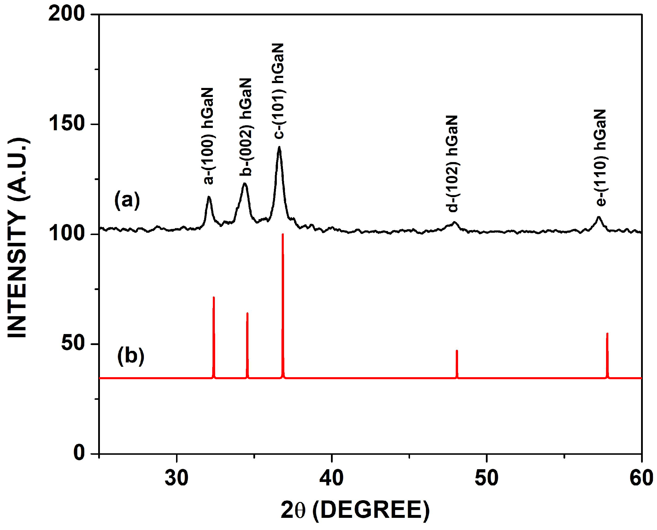
Mg-Zn co-doped GaN films were deposited on silicon substrates via radio-frequency magnetron sputtering in a N2-Ar2 environment. Figure 2 shows the X-ray diffraction patterns of Mg-Zn co-doped GaN films (Figure 2a), which were indexed in the ICDD PDF card No. 00-050-0792 (Figure 2b). In Figure 2a, the a peak belongs in the (100) plane, the b peak is located in the (002) plane, the c peak belongs in the (101) plane, the d peak is located in the (102) plane, and the e peak belongs in the (110) plane. The lattice constants were calculated using the ICDD PDF card No. 00-050-0792 for the hexagonal structure, with a = 3.1 Å and c = 5.1 Å for the space group P63mc and with a c/a ratio of 1.6. The X-ray diffraction patterns in Figure 2a show an FWHM of 0.54° for the a peak, with a crystal size of 15.9 nm and an interplanar spacing of 2.7 Å. The FWHM measure for the b peak had a value of 0.9°, with a crystal size of 9.0 nm and an interplanar spacing of 2.6 Å. The c peak had an FWHM of 0.67°, with a crystal size of 12.9 nm and an interplanar spacing of 2.4 Å, while the d peak had an FWHM of 0.71°, with a crystal size of 12.7 nm and an interplanar spacing of 1.9 Å. Finally, the e peak had an FWHM of 0.53°, with a crystal size of 17.6 nm and an interplanar spacing of 1.6 Å. It is important to mention that the crystallite size of each peak was calculated using the Scherrer equation, shown below:
D = K λ β cos θ
where D is the average crystallite size (nm), K is the Scherrer constant (0.94), λ is the X-ray wavelength (Cu Kα = 1.5 Å), β is the line broadening at FWHM in radians, and θ is Bragg’s angle in degrees, half of 2θ. Furthermore, using the ICCD PDF-4+2022 software and the Debye–Scherrer equation, the average crystal size was calculated, and a value of 13.6 nm was found, which could indicate that the widening of the peaks in Figure 2a might be associated with the presence of nanocrystallites, as demonstrated by Garcia et al. [17]. The more defined XRD peaks shown in this work would be related to the environment of nitrogen with argon (50–50%) for the Mg-Zn co-doped GaN films, which contrasts with the XRD peaks in a nitrogen environment (100%) presented in our previous work [16].

3.2. Electron Microscopy

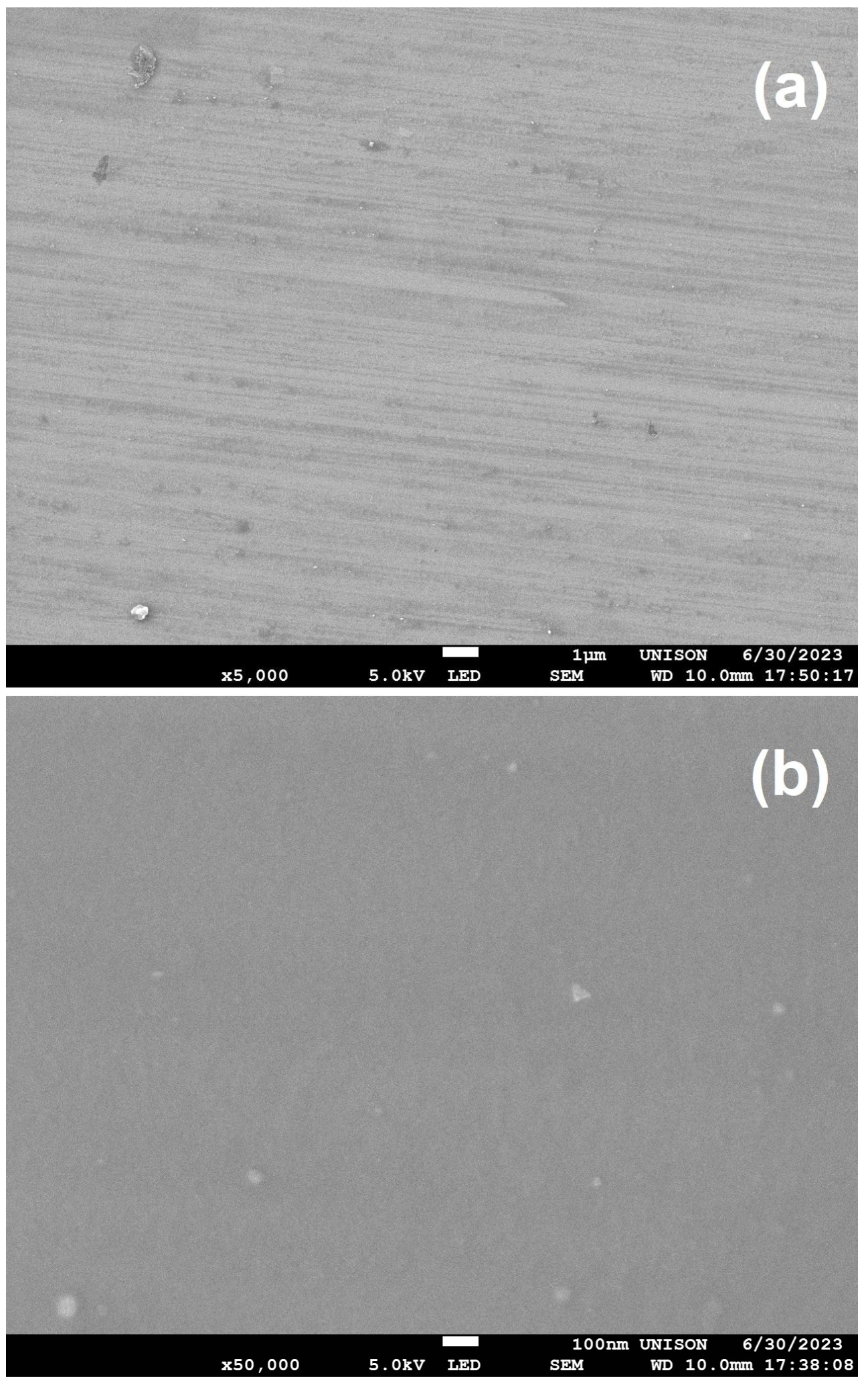
Figure 3 shows the SEM micrographs for the Mg-Zn co-doped GaN films. Figure 3a demonstrates a surface morphology where the deposition via radio-frequency magnetron sputtering generated good cohesion between the silicon substrate and the film with a magnification of X5000. Furthermore, a good uniform morphology can be observed in Figure 3a. Figure 3b also shows good homogeneity in the deposition of the Mg-Zn co-doped GaN films with a magnification of X50,000; however, little agglomerates could be observed on the surface, which might be related to structural defects such as oxygen interstitial. This oxygen interstitial could be formed during the hysteresis effect due to growth via radio-frequency magnetron sputtering [16].
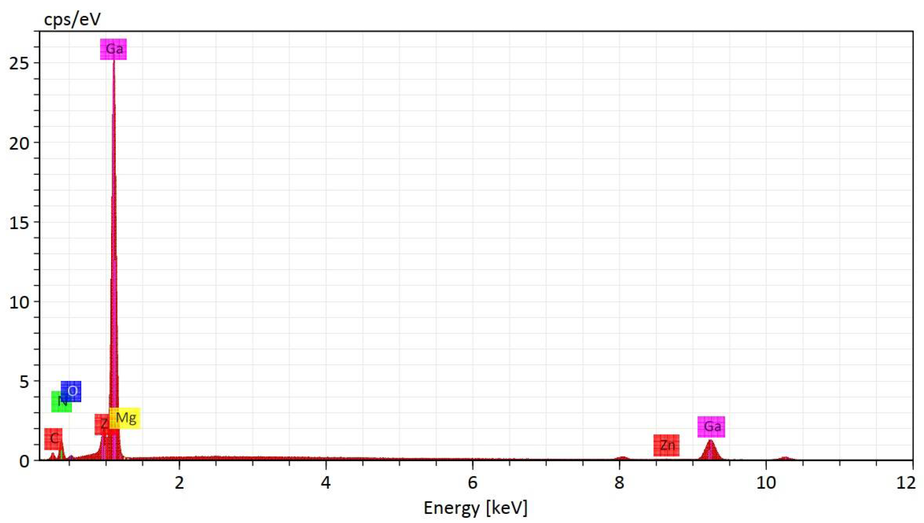
Figure 4 shows the EDS spectrum of the elemental analysis of the Mg-Zn co-doped GaN films, where elemental contributions of gallium were found at Lα-1.098 eV and Kα-9.2 eV. In addition, the elemental contribution of nitrogen was found at Kα-0.3 eV, and the elemental contribution of magnesium was found at Kα-1.2 eV. Finally, the elemental contribution of zinc was found at Lα-1.0 eV. The atomic percentages in the EDS analysis were gallium (49.66%), nitrogen (31.81%), zinc (0.60%), magnesium (0.32%), oxygen (1.87%), and carbon (15.73%). Furthermore, located at 8 eV, the presence of a small copper signal belonging to the sample holder of the EDS system is shown. To find the thickness of the Mg-Zn co-doped GaN films deposited by radio-frequency magnetron sputtering in a N2-Ar2 environment, which had a value of 260.2 nm, the technique of profilometry was used. The EDS analysis of the Mg-Zn co-doped GaN powders with which the target for the deposition of the films was prepared was carried out in ref. [14].
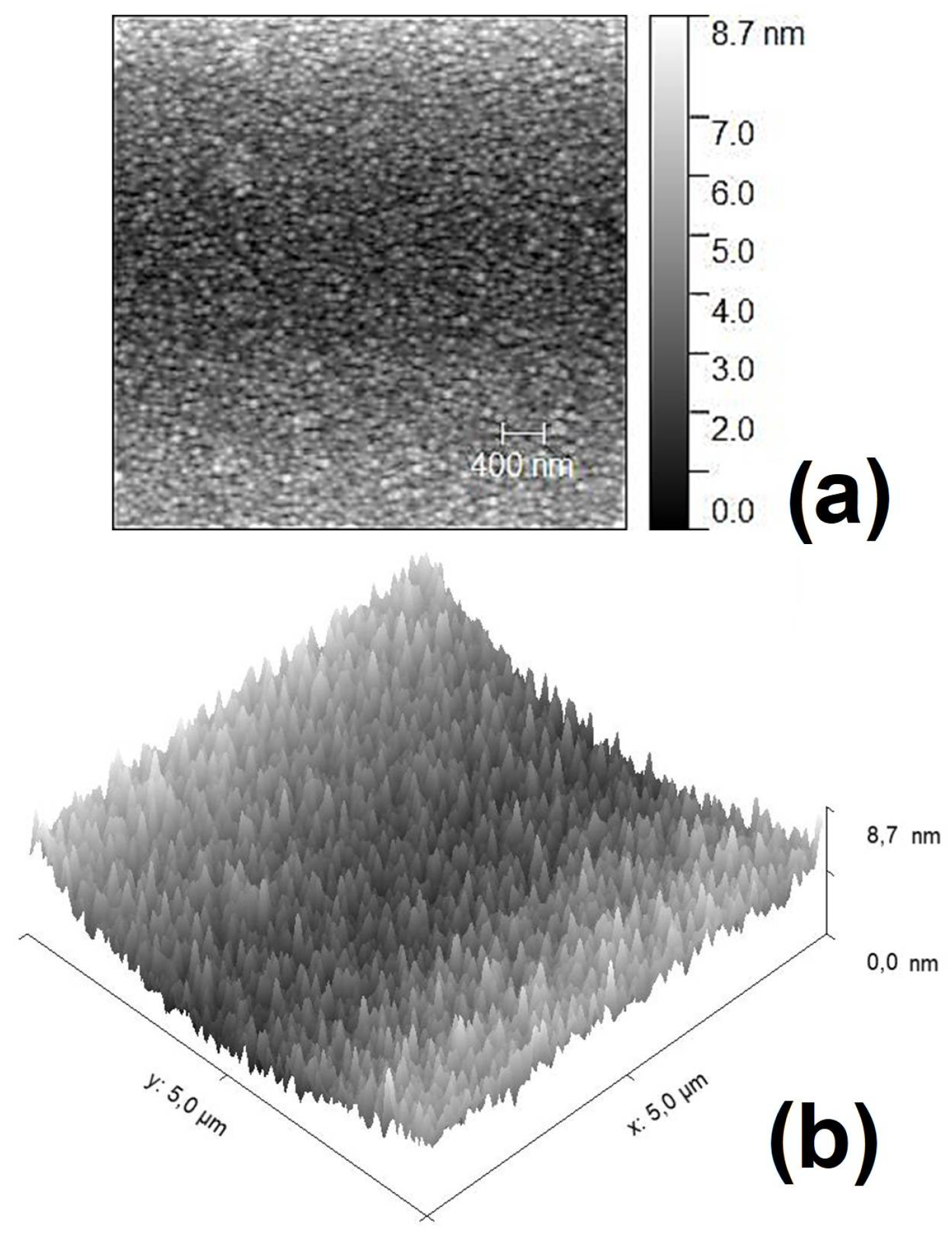
Figure 5 shows the analysis of surface topography using the technique of atomic force microscopy (AFM). Figure 5 illustrates 2D (Figure 5a) and 3D (Figure 5b) topographical AFM images of the Mg-Zn co-doped GaN films. The AFM images were measured over an area of 5 × 5 µm2. In Figure 5, using the software Gwyddion 2.63, a mean roughness of 1.1 nm was calculated, while the root mean square roughness was 1.3 nm and the maximum peak height was 5.0 nm. These AFM images demonstrate good surface morphology, besides good homogeneity, which agrees with the SEM micrographs of the deposition of the Mg-Zn co-doped GaN films [9,18,19].

3.3. X-ray Photoelectron Spectroscopy

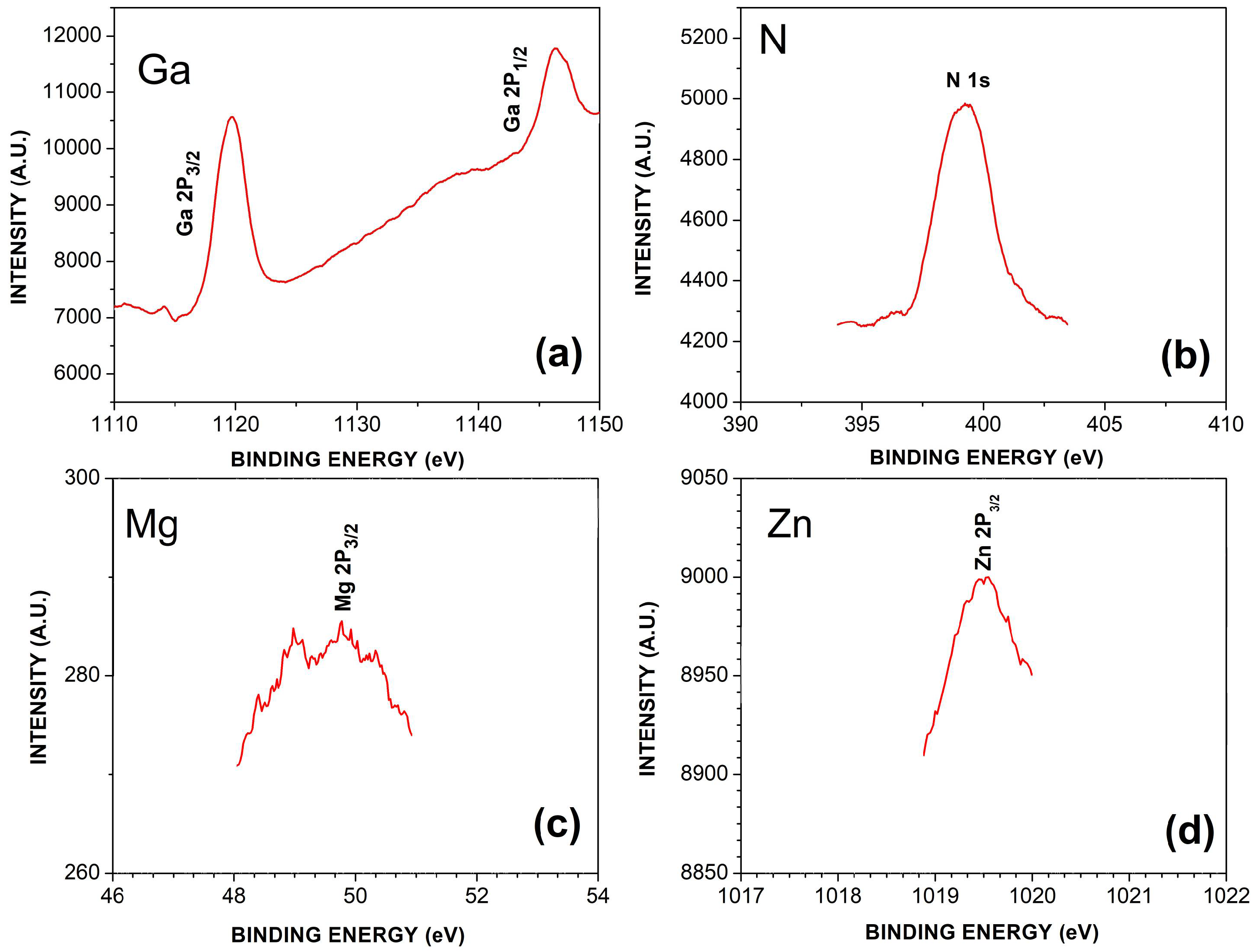
Figure 6 shows the XPS spectra of the Mg-Zn co-doped GaN films deposited by radio-frequency magnetron sputtering in a N2-Ar2 environment. Figure 6a presents the peaks for high energies of Ga 2P1/2 and Ga 2P3/2, with values of 1146.3 eV and 1119.7 eV, respectively. Figure 6b presents the N 1s peak with an energy value of 399.2 eV. Figure 6c presents the Zn 2P3/2 peak with an energy value of 1019.4 eV, while Figure 6d shows the Mg 2P3/2 peak with a binding energy of 49.7 eV. These results agree with those found in the EDS analysis, due to the presence of the elemental contributions of gallium, nitrogen, magnesium, and zinc.

3.4. Photoluminescence

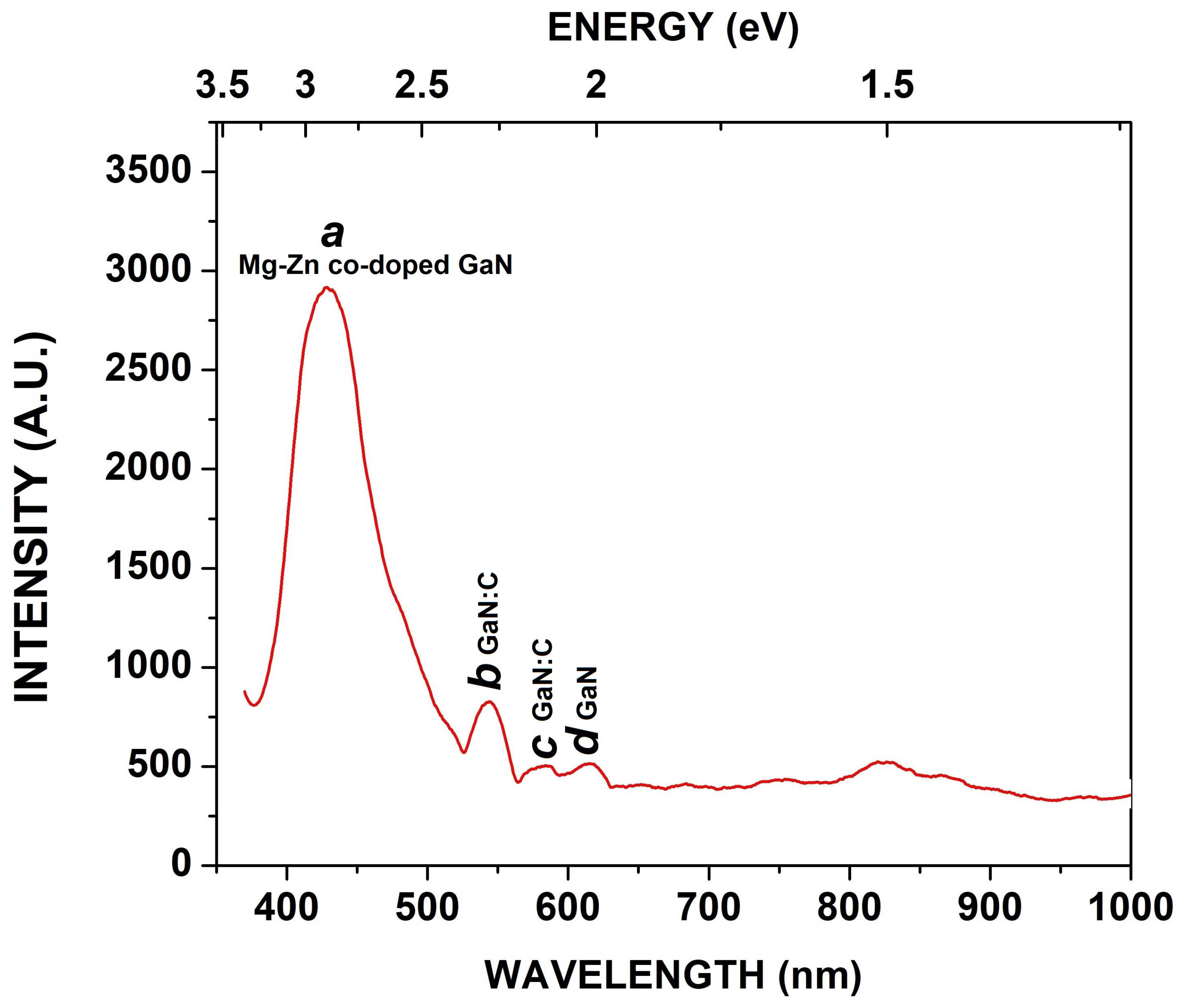
Figure 7 shows the photoluminescence spectrum for the Mg-Zn co-doped GaN films deposited by radio-frequency magnetron sputtering in a N2-Ar2 environment. Figure 7 demonstrates four energy emissions. The a (Mg-Zn co-doped GaN) energy emission corresponds to 2.8 eV (430.5 nm) and could be related to the incorporation of magnesium and zinc atoms. The blue luminescence (BL) for the incorporation of zinc atoms into GaN has a value of 2.8 eV, while the blue luminescence (BL) for the incorporation of magnesium atoms into GaN has a value from 2.7 to 3.0 eV [20,21]. Therefore, this value of energy emission agrees with the incorporation of zinc and magnesium into GaN for obtaining the co-doping, besides agreeing with the EDS and XPS analyses. The b (GaN:C) energy emission is located at 2.2 eV (546.2 nm) and could be related to non-intentional impurities of carbon in yellow luminescence (YL). These carbon impurities might be due to a little elemental contribution that appears in the EDS analysis, besides impurities belonging to the Mg-Zn co-doped GaN powders with which the target was made, which were transferred to the film in the deposition by sputtering. The c (GaN:C) energy emission located at 2.1 eV (582.1 nm) is also related to non-intentional impurities of carbon, while the d (GaN) energy emission is located at 2.0 eV (620 nm) and belongs to the red luminescence (RL) of GaN.

4. Conclusions

Mg-Zn co-doped GaN films were deposited by radio-frequency magnetron sputtering in a N2-Ar2 environment at room temperature using a target prepared with Mg-Zn co-doped GaN powders. The X-ray diffraction patterns (XRD) showed a higher intensity peak with an FWHM of 0.67°, a crystal size of 12.9 nm, an interplanar spacing of 2.4 Å, and an average crystal size of 13.6 nm. SEM micrographs showed good homogeneity in the deposition, which agrees with the AFM images with a mean roughness of 1.1 nm. The profilometry had a value of 260.2 nm for the thickness of the Mg-Zn co-doped GaN films. The EDS spectrum and the XPS analysis demonstrated the presence of gallium and nitrogen as elemental contributions, besides the co-doping with zinc and magnesium. Finally, the PL spectrum showed that the fundamental energy emission corresponds to 2.8 eV (430.5 nm) and could be related to the incorporation of magnesium and zinc atoms in the blue luminescence (BL). In addition, PL analysis also demonstrated carbon impurities belonging to the Mg-Zn co-doped GaN powders with which the target was made and that were transferred to the film in the deposition by sputtering, which agrees with the EDS analysis.

Author Contributions

Conceptualization, E.G.; Methodology, Formal Analysis, Investigation, Writing—Original Draft, Resources, R.G.; Formal Analysis, Investigation, Writing—Original Draft, A.M.H.; Resources, A.R.; Conceptualization, G.G.; Resources, G.A.H.; Resources, J.A.L.; Resources, J.A.R.; Resources, M.R.; Validation, Y.D.R.; Resources, I.E.G. All authors have read and agreed to the published version of the manuscript.

Funding

This research received no external funding.

Data Availability Statement

Data are contained within the article.

Acknowledgments

The authors gratefully acknowledge the technical support of CNyN-UNAM, DF-UNISON, and IFUAP-BUAP. This research was partially supported by CONAHCyT (Mexico), DIFUS-UNISON, and UTPuebla.

Conflicts of Interest

The authors declare no conflicts of interest.

References

  1. Wassen, M.; Adel, E.; Laoucine, K. The Global Semiconductor Chip Shortage: Causes, Implications, and Potential Remedies. IFAC-PapersOnLine 2022, 55, 476–483. [Google Scholar] [CrossRef]
  2. Kwon, W.; Kawasaki, S.; Watanabe, H.; Tanaka, A.; Honda, Y.; Ikeda, H.; Iso, K.; Amano, H. Reverse Leakage Mechanism of Dislocation-Free GaN Vertical p-n Diodes. IEEE Electron Device Lett. 2023, 44, 1172–1175. [Google Scholar] [CrossRef]
  3. Fanciulli, M.; Lei, T.; Moustakas, T.D. Conduction-electron spin resonance in zinc-blende GaN thin films. Phys. Rev. B 1993, 20, 15-144–15-147. [Google Scholar] [CrossRef] [PubMed]
  4. Sami, B.; Burak, T.; Cagla, O.-A.; Necmi, B.; Kemal, O.A. Electronic and optical device applications of hollow cathode plasma assisted atomic layer deposition based GaN thin films. J. Vac. Sci. Technol. A Vac. Surf. Film. 2015, 33, 01A143. [Google Scholar] [CrossRef]
  5. Lee, D.S.; Lee, J.H.; Lee, Y.H.; Lee, D.D. GaN thin films as gas sensors. Sens. Actuators B 2003, 89, 305–310. [Google Scholar] [CrossRef]
  6. Huang, S.; Zhang, Y.; Leung, B.; Yuan, G.; Wang, G.; Jiang, H.; Fan, Y.; Sun, Q.; Wang, J.; Xu, K.; et al. Mechanical Properties of Nanoporous GaN and Its Application for Separation and Transfer of GaN Thin Films. ACS Appl. Mater. Interfaces 2013, 5, 11074–11079. [Google Scholar] [CrossRef] [PubMed]
  7. Jung, H.S.; Hong, Y.J.; Li, Y.; Cho, J.; Kim, Y.J.; Yi, G.C. Photocatalysis Using GaN Nanowires. ACS Nano 2008, 2, 637–642. [Google Scholar] [CrossRef]
  8. Liu, W.-S.; Chang, Y.-L.; Tan, C.-Y.; Tsai, C.-T.; Kuo, H.-C. Properties of N-Type GaN Thin Film with Si-Ti Codoping on a Glass Substrate. Crystals 2020, 10, 582. [Google Scholar] [CrossRef]
  9. Sun, L.; Liu, C.; Li, J.; Wang, J.; Yan, F.; Zeng, Y.; Li, J. Structural and magnetic properties of GaN:Sm:Eu films fabricated by co-implantation method. Mater. Lett. 2010, 64, 1031–1033. [Google Scholar] [CrossRef]
  10. Jeong, M.C.; Ham, M.H.; Myoung, J.M.; Noh, S.K. Room-temperature ferromagnetism of Mg and Mn co-doped GaN films grown by PEMBE. Appl. Surf. Sci. 2004, 222, 322–326. [Google Scholar] [CrossRef]
  11. Kim, K.S.; Yang, G.M.; Lee, H.J. The study on the growth and properties of Mg doped and Mg–Si codoped p-type GaN. Solid-State Electron. 1999, 43, 1807–1812. [Google Scholar] [CrossRef]
  12. Kim, K.S.; Han, M.S.; Yang, G.M.; Youn, C.J.; Lee, H.J.; Cho, H.K.; Lee, J. Codoping characteristics of Zn with Mg in GaN. Appl. Phys. Lett. 2000, 77, 1123–1125. [Google Scholar] [CrossRef]
  13. Naito, A.; Ueno, K.; Kobayashi, A.; Fujioka, H. Hole Conduction Mechanism in In–Mg-Codoped GaN Prepared via Pulsed Sputtering Deposition. Phys. Status Solidi A 2024, 221, 2300806. [Google Scholar] [CrossRef]
  14. Gastellóu, E.; García, R.; Herrera, A.M.; Ramos, A.; García, G.; Hirata, G.A.; Luna, J.A.; Carrillo, R.C.; Rodríguez, J.A.; Robles, M.; et al. Obtaining of Mg-Zn Co-Doped GaN Powders via Nitridation of the Ga-Mg-Zn Metallic Solution and Their Structural and Optical Properties. Materials 2023, 16, 3272. [Google Scholar] [CrossRef]
  15. Gastellóu, E.; García, G.; Herrera, A.M.; Morales, C.; García, R.; Hirata, G.A.; Rosendo, E.; Luna, J.A.; Robles, M.; Rodríguez, J.A.; et al. Effects in the Optical and Structural Properties Caused by Mg or Zn Doping of GaN Films Grown via Radio-Frequency Magnetron Sputtering Using Laboratory-Prepared Targets. Appl. Sci. 2021, 11, 6990. [Google Scholar] [CrossRef]
  16. Jewett, S.A.; Makowski, M.S.; Andrews, B.; Manfra, M.J.; Ivanisevic, A. Gallium nitride is biocompatible and non-toxic before and after functionalization with peptides. Acta Biomater. 2012, 8, 728–733. [Google Scholar] [CrossRef] [PubMed]
  17. Garcia, R.; Hirata, G.A.; Thomas, A.C.; Ponce, F.A. Structure and luminescence of nanocrystalline gallium nitride synthesized by a novel polymer pyrolysis route. Opt. Mater. 2006, 29, 19–23. [Google Scholar] [CrossRef]
  18. Fang, J.; Yang, W.; Zhang, X.; Tian, A.; Lu, S.; Liu, J.; Yang, H. The Effect of Periodic Duty Cyclings in Metal-Modulated Epitaxy on GaN:Mg Film. Materials 2023, 16, 1730. [Google Scholar] [CrossRef]
  19. Kumar, A.; Berg, M.; Wang, Q.; Salter, M.; Ramvall, P. Growth of p-type GaN—The role of oxygen in activation of Mg-doping. Power Electron. Devices Compon. 2023, 5, 100036. [Google Scholar] [CrossRef]
  20. Reshchikov, M.A.; Morkoç, H. Luminescence properties of defects in GaN. J. Appl. Phys. 2005, 97, 061301-1–061301-95. [Google Scholar] [CrossRef]
  21. Furqan, C.M.; Ho Jacob, Y.L.; Kwok, H.S. GaN thin film: Growth and Characterizations by Magnetron Sputtering. Surf. Interfaces 2021, 26, 101364. [Google Scholar] [CrossRef]
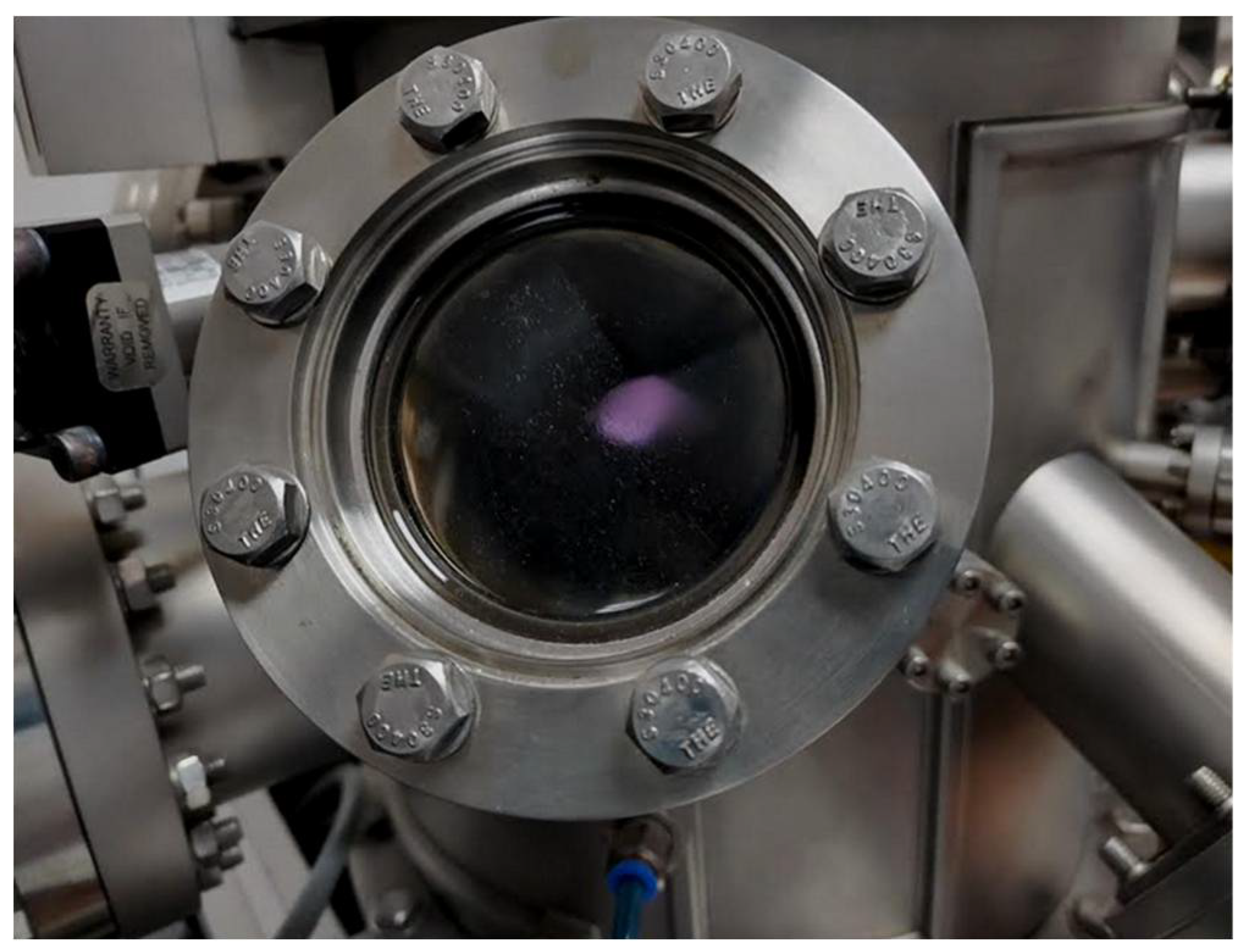
Figure 1. Violet plasma is generated during the deposition of the Mg-Zn co-doped GaN films.
Crystals 14 00618 g001
Figure 2. X-ray diffraction patterns: (a) Mg-Zn co-doped GaN films deposited by radio-frequency magnetron sputtering in N2-Ar2 environment; (b) ICDD PDF card No. 00-050-0792.
Crystals 14 00618 g002
Figure 3. SEM micrographs of Mg-Zn co-doped GaN films with magnifications of (a) X5000, and (b) X50,000.
Crystals 14 00618 g003
Figure 4. EDS analysis of Mg-Zn co-doped GaN films deposited by radio-frequency magnetron sputtering in N2-Ar2 environment.
Crystals 14 00618 g004
Figure 5. (a) Two-dimensional and (b) three-dimensional AFM images of Mg-Zn co-doped GaN films deposited by radio-frequency magnetron sputtering in N2-Ar2 environment.
Crystals 14 00618 g005
Figure 6. XPS spectra for Mg-Zn co-doped GaN films deposited by radio-frequency magnetron sputtering in N2-Ar2 environment: (a) Ga 2P3/2 and Ga 2P1/2, (b) N 1s, (c) Mg 2P3/2, (d) Zn 2P3/2.
Crystals 14 00618 g006
Figure 7. Photoluminescence spectrum of Mg-Zn co-doped GaN films deposited by radio-frequency magnetron sputtering in N2-Ar2 environment.
Crystals 14 00618 g007
Disclaimer/Publisher’s Note: The statements, opinions and data contained in all publications are solely those of the individual author(s) and contributor(s) and not of MDPI and/or the editor(s). MDPI and/or the editor(s) disclaim responsibility for any injury to people or property resulting from any ideas, methods, instructions or products referred to in the content.