Article

Effect of Initial Intergranular Ferrite Size on Induction Hardening Microstructure of Microalloyed Steel 38MnVS6

1
R&D Center, Beijing Benz Automotive Co., Ltd., Beijing 100176, China
2
Engine Plant, Beijing Benz Automotive Co., Ltd., Beijing 100176, China
*
Author to whom correspondence should be addressed.
Crystals 2024, 14(9), 827; https://doi.org/10.3390/cryst14090827
Submission received: 28 August 2024 / Revised: 13 September 2024 / Accepted: 19 September 2024 / Published: 22 September 2024
(This article belongs to the Section Crystalline Metals and Alloys)

Abstract

:
In this study, we investigated the effect of grain size of an initial microstructure (pearlite + ferrite) on a resulting microstructure of induction-hardened microalloyed steel 38MnVS6, which is one topical medium carbon vanadium microalloyed non-quenched and tempered steel used in manufacturing crankshafts for high-power engines. The results show that a coarse initial microstructure could contribute to the incomplete transformation of pearlite + ferrite into austenite in reaustenitization transformation by rapid heating, and the undissolved ferrite remains and locates between the neighboring prior austenite grains after the induction-hardening process. As the coarseness level of the initial microstructure increases from 102 μm to 156 μm, the morphology of undissolved ferrite varies as granule, film, semi-network, and network, in sequence. The undissolved ferrite structures have a thickness of 250–500 nm and appear dark under an optical metallographic view field. To achieve better engineering applications, it is not recommended to eliminate the undissolved ferrite by increasing much heating time for samples with coarser initial microstructures. It is better to achieve a fine original microstructure before the induction-hardening process. For example, microalloying addition of vanadium and titanium plays a role of metallurgical grain refinement via intragranular ferrite nucleation on more sites, and the heating temperature and time of the forging process should be strictly controlled to ensure the existence of fine prior austenite grains before subsequent isothermal phase transformation to pearlite + ferrite.

1. Introduction

Microalloying technology, developed in the 1960s, provided a theoretical basis for the non-quenched and tempered steel. The emergence of microalloyed non quenched and tempered steel was directly accelerated by the oil crisis. In 1972, THYSSEN in Germany developed novel non-quenched and tempered steels, and ferrite-pearlite steel 49MnVS3 was classically provided to automotive crankshaft manufacturers to replace quenched and tempered CK45 steel. Its advantages include a remarkably improved yield strength, higher production efficiency, higher fatigue performance, better machinability, and helping cut the cost of forged steel components [1]. This group of steels has been used to produce crankshafts, connecting rods, steering arms, and different axles in the auto industry [2]. For example, Mercedes Benz in Germany manufactured crankshafts using non-quenched and tempered steels instead of 40CrMn quenched and tempered steel, and Volvo in Sweden employed over 30,000 t of the steels annually in the early 1990s, with the goal of producing all forgings using non quenched and tempered steels, except for carburized parts. Subsequently, microalloyed non-quenched and tempered steels achieved rapid development globally and became the preferred material for automotive crankshafts all over the world. For example, it dominates 90% of crankshafts in the current market of Japan’s automotive industry and more than 70% of forgings in the German automotive industry. Microalloyed steels can be strength-enhanced by dealing with aspects of precipitation which controls grain size and dispersion strengthening in ferrite–pearlite steels [3]. It mainly depends on the solid solution strengthening effect of alloying elements and the precipitation strengthening of resulting carbides, nitrides, and carbonitrides, since the solid solution atoms cause lattice distortion, and the precipitation of carbonitrides hinders dislocation movement [4]. Microalloying with V element is an efficient method of dispersion strengthening [5] for medium carbon ferrite–pearlite steels, in addition to grain refinement by ferrite nucleation on VN particles [6], thus providing improved mechanical properties [7]. The degree of precipitation strengthening of ferrite at a given vanadium content depends on the available quantities of carbon and nitrogen [8]. Reheating temperature and direct-cooling rate after forging and compositions of microalloyed steels highly influence the microstructure and therefore play an important role on final microstructure and resulting mechanical properties [9].
As an excellent representative of Mn-V series microalloyed steels, steel 38MnVS6 has become a research hotspot and has achieved remarkable results in recent years [10,11,12,13,14,15,16]. Manganese sulfides usually form because of more S addition, which can improve the machinability of this steel. MnS is detrimental to anti-pitting behavior [17,18] and it could be improved by tellurium treatment to increase pitting resistance [19]. On the other hand, MnS behaves as internal stress concentrations and lowers the fatigue strength and life due to an effect characterized by a function of shape factor γ (length-to-width ratio) of the MnS [12]. The application of induction hardening treatment plays a vital role for enhancing fatigue life because of compressive residual stresses incorporated in the component to a significant extent [13]. The microstructure and resultant mechanical properties of the hardened case produced in steels have a dependence on heating and cooling rate, maximum temperature of the treatment, composition, and initial microstructure [20]. Effects of the initial microstructure on the induction hardening behavior of microalloyed steels have been reported. However, the samples of microalloyed steels in the previous research are relatively designed with remarkable differences in initial microstructures involving bainite–martensite [21], or ferrite–martensite/austenite [21], isothermal upper and lower bainite [22]. There is no literature reporting the size effect of the same initial microstructures on induction hardening of microalloyed steels. In this research, samples are prepared with same initial microstructure of pearlite + ferrite, and the difference between them is the network dimension of intergranular ferrite. The effect of intergranular ferrite size on the resulting microstructure of induction-hardened microalloyed steels is investigated. This investigation could be provided with important reference for engineering practice of induction hardening in high-power gasoline engine crankshafts.

2. Materials and Methods

2.1. Raw Material

The experimental material in this study is a medium carbon microalloyed steel 38MnVS6 produced via continuous casting. The chemical composition of steel 38MnVS6 meets the requirements of standard DIN EN 10267-1998 [23], as shown in Table 1. The crankshafts prepared for the study were treated to a hardness range of 250–300 HBRW by controlled cooling after hot forging. The obtained structure was pearlite + ferrite, without bainite. Three batches of crankshafts were produced with different initial intergranular ferrite sizes, named Batch A, Batch B, and Batch C. The differences between these batches were produced by the process parameters in hot forging, including controlled heating temperature, holding time, forging ratio, and finishing temperature. The journals were machined with a finished diameter of 55 mm in the study, ready for the induction hardening process.

2.2. Induction Hardening

In total, three pcs of crankshafts from each batch were selected randomly for induction hardening. Half journals of each crankshaft were subsequently quenched by quenching coolant. The other half were kept for raw microstructure inspection after heat treatment. Intermediate frequency induction hardening was carried out by a BAZ-2 typed machine. The average power was 58 kW, and the frequency was 11 kHz. Induction heating time was set at 10 s, with 88% intermediate frequency voltage. The temperature of the quenching coolant was 22 °C in an ambient environment and the coolant cooling time was 4 s.

2.3. Microstructural Characterization

Metallurgical specimens were cut from the crankshaft journals along the radial direction. Hot mounting was used with powder resin material. The samples were ground and polished, following the details in Table 2, and then etched by 4% nital solution for several seconds until the surfaces appeared gray in color. The prepared samples were analyzed using an optical microscope. A scanning electron microscope (SEM) was employed to observe the morphological features of quenched microstructures with high resolution under 6000 magnifications. Electron backscatter diffraction (EBSD) was used to further identify the dark phase.

3. Results

3.1. Initial Microstructure

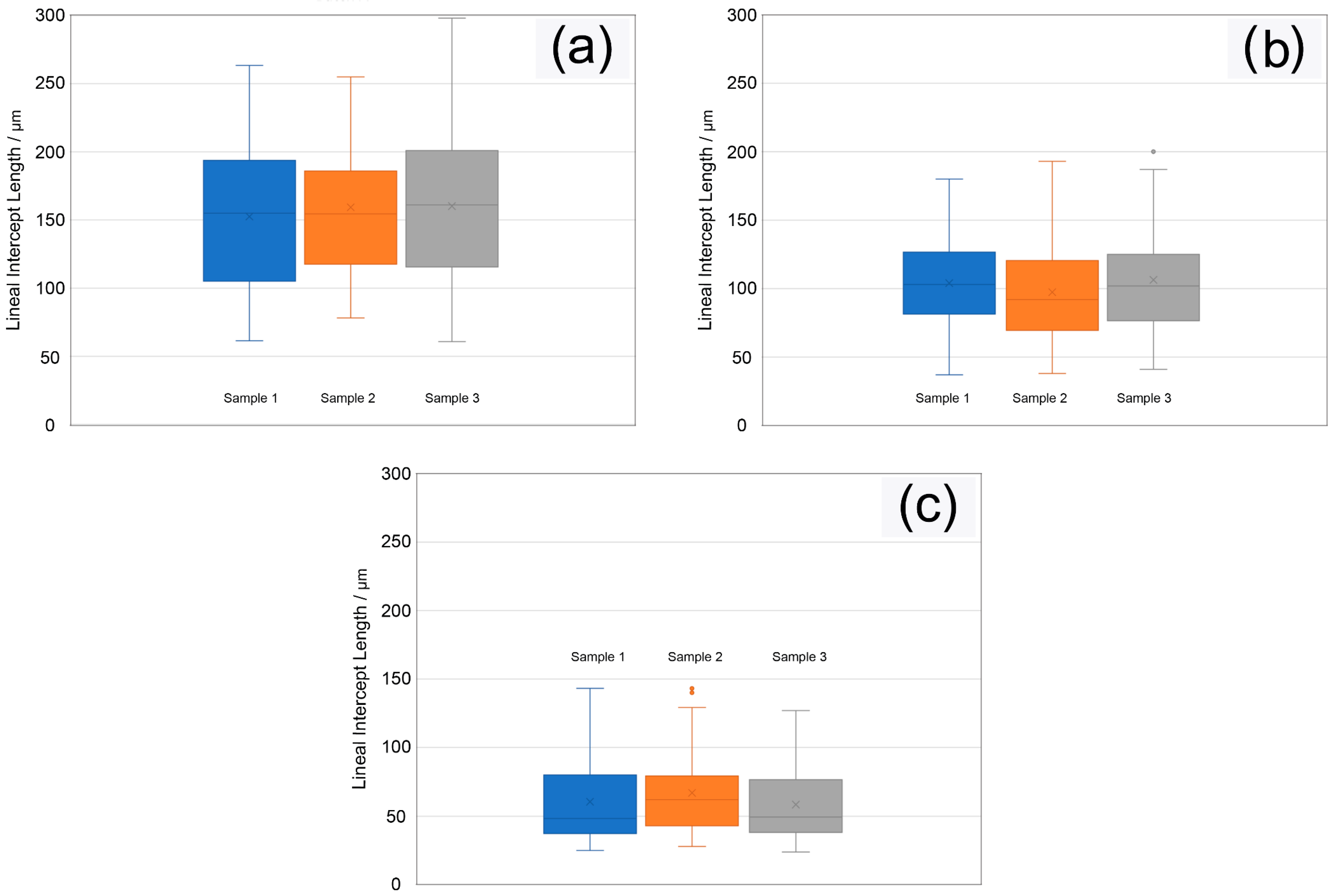
Figure 1, Figure 2 and Figure 3 reveal the initial microstructure prepared in this study. The initial microstructure mainly consists of intergranular ferrite and intragranular pearlite colonies. The order of intergranular ferrite from coarse to fine is Batch A, Batch B, and Batch C, respectively. The smaller the intergranular ferrite size, the more intragranular ferrite granules were present. To quantitatively characterize intergranular ferrite size, a method to collect and calculate mean lineal intercept length l on the measuring lines has been introduced, following standard ISO 643:2024 Steels—Micrographic determination of the apparent grain size [24]. Quantitative statistical results are represented in Table 3. The mean lineal intercept length of initial intergranular ferrite of Batch A is 156 μm, Batch B 102 μm, and Batch C 62 μm. Box diagrams in Figure 4 expound the statistical distribution of mean lineal intercept length of the initial intergranular ferrite.

3.2. Induction Hardened Microstructure

During the heating procedure of the induction-hardening process, the most ideal situation is that that reaustenitization from the initial microstructure of ferrite and pearlite is accomplished in three stages, including nucleation, growth, and homogenization of austenite within a very short period. The crankshaft samples are reheated at fast heating rates, and the austenite formation mechanism and kinetics are controlled by the diffusion of mainly carbon atoms. Martensite would form from austenite at a rapid cooling rate during the following quenching process. Any untransformed ferrite, or non-hardened phase such as sorbite, is not desirable to be attained. As stated above, the original microstructure has an influence on the induction hardening behavior of microalloyed steels. In this study, different induction quenching microstructures were obtained based on the original microstructures of different sizes of initial intergranular ferrite. Figure 5 shows the resulting microstructure of Batch A with initial intergranular ferrite size of 156 μm. It can be seen that dark phases in the form of semi-network and network interestingly appear as prior austenite grain boundaries in the conventional micrographic determination of the apparent grain size. As the size of the initial intergranular ferrite reduces, dark semi-network and network would disappear in the resulting microstructure. However, the presence of dark phase in the form of granules and film is easily to be affirmed as shown in Figure 6, for Batch B with an initial intergranular ferrite size of 102 μm. When initial intergranular ferrite size decreases to 62 μm, no dark phase in any form appears in the resulting microstructure of mainly martensite (M’), with a few retained austenites (RA) in Figure 7. This is the normal induction hardened microstructure, providing higher hardness and wear property to crankshaft journals.

3.3. Identification of Dark Phase

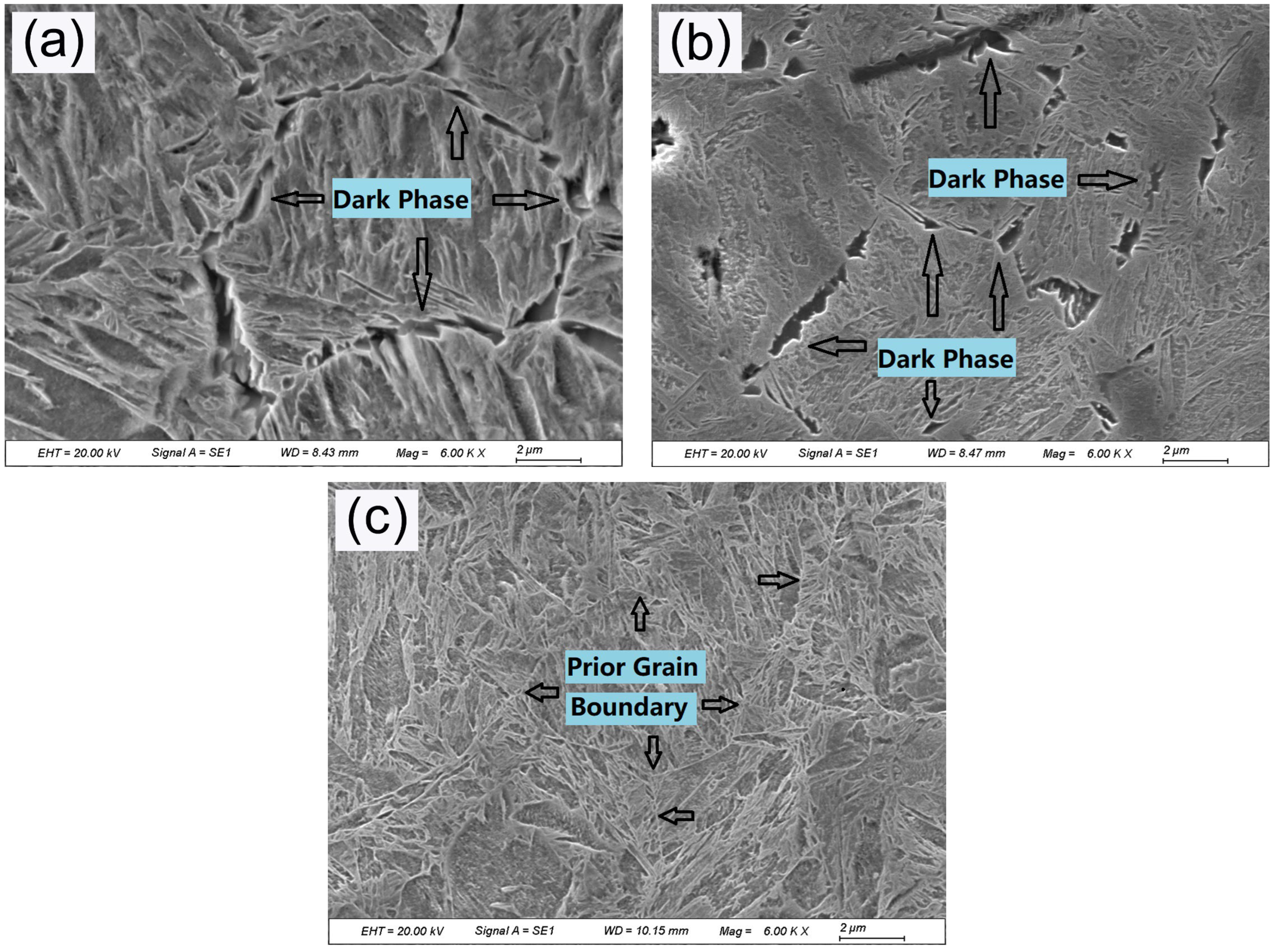
To identify the metallurgical properties of the dark phase in Batch A and Batch B, secondary electron (SE) images obtained in the SEM experiment reveal the details of morphological characteristics of dark phases in the three-dimensional direction. It is more easily etched by 4% nital solution, and appears in a gully shape, as arrowed in Figure 8a,b, which is representative of Batch A and Batch B, respectively. As a comparison, Figure 8c shows a normal induction-hardened microstructure in Batch C. The prior austenite grain boundaries are clear and distinguishable, completely different from the dark phase structure. The speculation that the dark phase might be austenite grain boundaries can be eliminated. Based on metallographic experience, the dark phase should be recognized as ferrite. Note that the dark phases have a thickness range of 250–500 nm. It is too thin for an optical microscope to recognize clearly due to its resolution limitation at this scale. This is the fundamental reason why it looks dark in optical metallographic observation, while similar structures with larger sizes are well known as white ferrite by metallurgists [25,26,27,28,29]. The EBSD results provide more scientific experimental evidence that the dark phase is a BCC crystalline structure (see Figure 9). Image quality (IQ) maps indicate the ferrite (high IQ areas) and the martensite (low IQ regions). Additionally, the percentage of retained austenite phase is only 1.7%. Combining the experimental results of both SEM and EBSD, the dark phase could be accredited as ferrite.

4. Discussion

4.1. Effect of Initial Intergranular Ferrite Size

The resulting microstructures of induction hardening in different batches of crankshafts with different initial intergranular ferrite size are summarized in Table 4. It could be concluded that with the increasing size of initial intergranular ferrite, the presence of undissolved ferrite is a solid possibility. As coarseness level increases, the phenomenon of incomplete austenite transformation from initial microstructure gradually appears, and the form of undissolved ferrite varies as granule (GF), film (FF), semi-network (SNF), and network (NF), in sequence. With respect to the overall transformation in a previous study [30], a finer microstructure results in a faster process of dissolution from the initial microstructure, as compared with coarser microstructures.
There are two different transformations in the austenitization of microstructures composed of ferrite and pearlite, involving pearlite dissolution and ferrite-to-austenite transformation, which take place by nucleation and growth processes [31]. Induction hardening is a heat treatment of non-isothermal reactions. The austenite volume fraction ( V γ P ), obtained from pearlite dissolution during continuous heating of a ferrite plus pearlite initial microstructure, could be expressed as follows [31]:
V γ P = V P 0 1 e x p A c 1 T 4 π 3 4 G 3 Δ T 3 d T
where V P 0 is the volume fraction of pearlite present in the initial microstructure, T is heating temperature, ΔT is overheating (ΔT = TAc1), and G are nucleation and growth rates of austenite, is a constant rate for the heating condition, and Ac1 is the eutectoid temperature using Andrews’ formula [32].
Pearlite-to-austenite transformation could be completed within one second [33]. Once austenite transformation from the pearlite has been totally accomplished, the α/γ interface keeps advancing into the ferrite grains until all the initial microstructure has been reaustenitized [34]. It is newly shown that the critical temperatures for austenite formation migrate to higher levels when at a rapid heating rate [35]. The increase has no influence on the starting temperature of the austenite formation (Ac1), but it changes its final critical temperature (Ac3), which could be increased from 920 °C to 1035 °C [36]. This indicates that it requires a higher temperature for ferrite-to-austenite transformation. The kinetics of the ferrite-to-austenite transformation at higher temperatures (T ≥ 870 °C) become different, and the volume fraction of austenite formed from ferrite after complete pearlite-to-austenite transformation has primarily a time (t) dependence [30]. The volume fraction of austenite formed from ferrite during continuous heating at a given temperature could be expressed as follows [31]:
V γ α = V α 0 V α 0 V D α 2 2 + 1.2 × 10 3 V α 0 V D α T T C 2 T D T C 2
where TC is the starting temperature of ferrite-to-austenite transformation, TD is the temperature at which the kinetics of ferrite-to-austenite transformation change under non-isothermal conditions. TC and TD temperatures could be determined experimentally by means of dilatometric analysis. V D α is the austenite volume fraction formed from ferrite at TD temperature, and V α 0 is the volume fractions of ferrite present in the initial microstructure.
It Is the time dependence in the heating period of the induction-hardening process that causes the difference in the resulting microstructures in crankshafts with different initial intergranular ferrite size. The increase in temperature is a function of heating time, and the diffusion of carbon atoms in austenite transformation is also a function of heating time. For the coarser initial intergranular ferrite, it needs more time for carbon to diffuse into ferrite with a longer distance during the final stage of ferrite-to-austenite transformation, which is diffusion controlled. From the experimental result, it could be inferred that the designed heating parameters could only achieve the completed reaustenitizating transformation for samples of Batch C. However, it is slightly inadequate for Batch A and Batch B, hence a very small amount of ferrite remains undissolved right between neighboring prior austenite grains which are in growth before the quenching process and exists in final quenching microstructure.

4.2. Actions Preventing Dark Ferrite

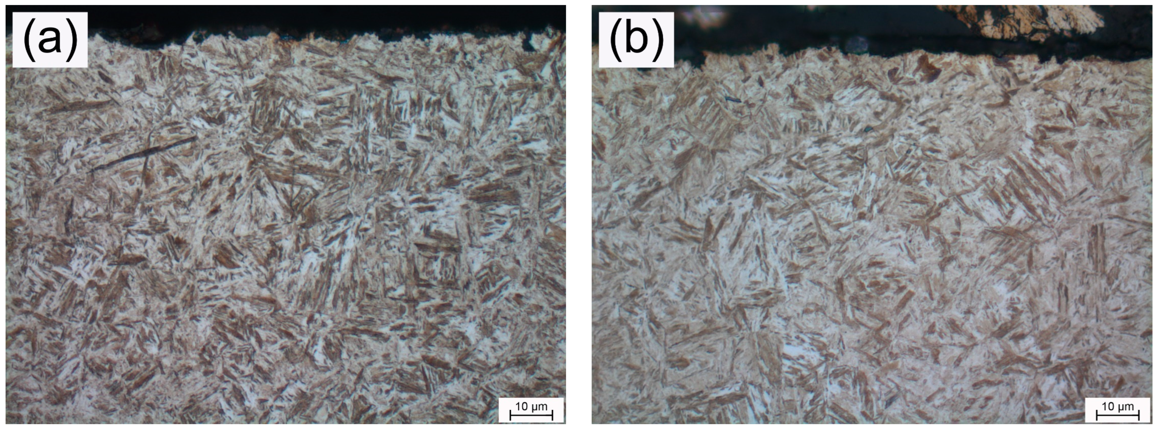
For the given non-quenched and tempered microalloyed steel with coarser grains, more heat is required to achieve an austenitizing transformation from ferrite and pearlite. To avoid undissolved dark ferrite in the induction-hardening process, heating time has been designed with additional two seconds for rest crankshafts from Batch A and Batch B, and other process parameters remain unchanged. Figure 10 shows the induction hardening microstructure after process improvement. The tempered martensite morphology can be clearly seen with a very small amount of residual austenite, and the previous undissolved dark ferrite has disappeared. This experimental result could serve as evidence to support the previous assertion about insufficient austenitization that caused the existence of undissolved dark ferrite.
However, these original structures coarser than grain size 5 are usually considered to be detrimental to fatigue performance. Hence, the above induction-hardening process optimization is not the best solution. Microstructural optimization shall be carried out before the induction hardening process. According to the results of this experiment, controlling grain size of the intergranular ferrite can suppress the undissolved dark ferrite in induction hardening process. Grain size of intergranular ferrite can be controlled dominantly through the following two methods: metallurgical microalloying via alloy composition design, and, subsequently, deformation degree and deformation temperature controlling in the forging process. The influence of microalloying via the addition of elements V [37,38], Nb [39,40], Ti [41,42], and Te [43] could prevent austenite grain coarsening development; therefore, intergranular ferrite could be refined by the precipitation of carbonitrides [44]. The forging deformation and deformation temperature play an important role in the microstructure of non-quenched and tempered steel. The finer grains can be obtained by increasing the deformation and reducing the deformation temperature [45]. Recent advances indicate that microstructural modification via a novel thermomechanical controlled processing [46] could lead to ferrite grain refinement by dynamic recrystallization and deformation-induced ferrite transformation. An appropriate isothermal holding period could be conducive to the nucleation and growth of fine carbides with FCC crystal structure which lead to ferrite refinement [47]; nevertheless, to decrease or to increase the isothermal holding time too much, precipitates coarseness and decreased grain refinement would take place [48].

5. Conclusions

In this study, the effect of initial intergranular ferrite size on resulting microstructure of induction hardened microalloyed steel 38MnVS6, which is a topical material for gasoline engine crankshaft, was revealed. The results show that the designed heating parameters could only achieve the completed reaustenitization transformation for samples with a fine initial microstructure. As the coarseness level of the initial microstructure increases from 102 μm to 156 μm, the phenomenon of incomplete austenite transformation from pearlite + ferrite initial microstructure gradually takes place by very rapid heating, and a very small amount of ferrite remains undissolved in the final quenching microstructure in the form of granules, films, semi-networks, and networks, in sequence, and exists right between neighboring prior austenite grains which are in growth before the quenching process. The undissolved ferrite structures have a thickness of 250–500 nm and appear dark under optical metallographic view field due to its resolution limitation at such a small scale. In addition, it has been experimentally confirmed that the undissolved ferrite can be eliminated by increasing the heating time for samples with coarse initial microstructures. However, the best optimization measure should be to achieve a fine original microstructure before the induction-hardening process, such as microalloying addition of vanadium and titanium to metallurgically provide more sites for intragranular ferrite nucleation, and strictly controlled heating temperature and time of the forging process before subsequent isothermal phase transformation to pearlite + ferrite. For more accurate characterization of the dark network ferrite discovered under an optical microscope in this study, more advanced and high-resolution characterization techniques and devices should be applied, such as transmission electron microscopy or atomic probe technology, to provide more direct experimental evidence to reveal its phase transition kinetics. On the other hand, the influence of the network ferrite in the induction quenched microalloyed steel on mechanical properties including hardness, toughness, and fatigue performance should be further investigated.

Author Contributions

Conceptualization, D.K. and C.Q.; methodology, D.K., W.D. and J.Z.; validation, L.C. and C.Q.; formal analysis, J.Z.; investigation, D.K. and C.Q.; resources, W.D. and L.C.; data curation, J.Z., W.D. and C.Q.; writing—original draft preparation, D.K. and J.Z.; writing—review and editing, D.K., W.D. and C.Q.; visualization, W.D.; supervision, W.D. and L.C.; project administration, W.D. and L.C.; funding acquisition, W.D. All authors have read and agreed to the published version of the manuscript.

Funding

This research was one program of “2024 Employee Innovation Promotion Plan” by Trade Union of Beijing Benz Automotive Co., Ltd.

Data Availability Statement

The raw data supporting the conclusions of this article will be made available by the authors on request due to privacy.

Acknowledgments

The authors offer thanks for the experimental and technical support to SEM and EBSD test from Yunling Li in Central Iron and Steel Research Institute Co., Ltd.

Conflicts of Interest

D.K., J.Z. and W.D. are employed by the company R&D Center, Beijing Benz Automotive Co., Ltd. L.C., and C.Q. are employed by the company Engine Plant, Beijing Benz Automotive Co., Ltd. All the authors declare that the research was conducted in the absence of any commercial or financial relationships that could be construed as a potential conflict of interest.

References

  1. Thewillis, G.; Naylor, D.J. New alloys help cut the cost of forged steel components. Met. Mater. 1981, 12, 21–28. [Google Scholar]
  2. Ko, Y.S.; Kim, S.H.; Park, H.; Lim, J.D. Assessment of microalloying effect to the new automotive forged steel parts. In Proceedings of the 2006 International Forum on Strategic Technology, Ulsan, Republic of Korea, 18–20 October 2006; pp. 170–173. [Google Scholar] [CrossRef]
  3. Baker, T.N. Microalloyed steels. Ironmak. Steelmak. 2016, 43, 264–307. [Google Scholar] [CrossRef]
  4. Zhao, M.; Hanamura, T.; Qiu, H.; Yang, K. Precipitation of carbonitrides and their strengthening upon non-quench aging for micro-alloyed acicular ferrite pipeline steels. Mater. Trans. 2005, 46, 784–789. [Google Scholar] [CrossRef]
  5. Baker, T.N. Processes, microstructure and properties of vanadium microalloyed steels. Mater. Sci. Technol. 2019, 25, 1083–1107. [Google Scholar] [CrossRef]
  6. Medina, S.F.; Gómez, M.; Rancel, L. Grain refinement by intragranular nucleation of ferrite in a high nitrogen content vanadium microalloyed steel. Scr. Mater. 2008, 58, 1110–1113. [Google Scholar] [CrossRef]
  7. Fang, W.; Zhang, C.; Gou, F.; Jiang, B.; Zhang, C.; Liu, Y. The effect of micro alloying elements (vanadium, titanium) additions on the austenite grain growth behavior in medium carbon steel containing nitrogen. Mater. Werkst. 2020, 51, 230–237. [Google Scholar] [CrossRef]
  8. Zajac, S.; Siwecki, T.; Hutchinson, W.B.; Lagneborg, R. Strengthening mechanisms in vanadium microalloyed steels intended for long products. ISIJ Int. 1998, 38, 1130–1139. [Google Scholar] [CrossRef]
  9. Dini, G.; Vaghefi, M.M.; Shafyei, A. The influence of reheating temperature and direct-cooling rate after forging on microstructure and mechanical properties of V-microalloyed steel 38MnSiVS5. ISIJ Int. 2006, 46, 89–92. [Google Scholar] [CrossRef]
  10. Gu, S.; Zhang, L.; Ruan, J.; Zhou, P.; Zhen, Y. Constitutive modeling of dynamic recrystallization behavior and processing map of 38MnVS6 non-quenched steel. J. Mater. Eng. Perform. 2014, 23, 1062–1068. [Google Scholar] [CrossRef]
  11. Gu, S.; Zhang, L.; Zhang, C.; Ruan, J.; Zhen, Y. Modeling the effects of processing parameters on dynamic recrystallization behavior of deformed 38MnVS6 steel. J. Mater. Eng. Perform. 2015, 24, 1790–1798. [Google Scholar] [CrossRef]
  12. Scurria, M.; Emre, S.; Möller, B.; Wagener, R.; Melz, T. Evaluation of the influence of MnS in forged steel 38MnVS6 on fatigue life. SAE Int. J. Engines 2017, 10, 366–372. [Google Scholar] [CrossRef]
  13. Lomate, D.; Tewari, A.; Date, P.; Ukhande, M.R.; Shegavi, G.M.; Singh, R.K.P. Fatigue life prediction of induction hardened case depth specimens made from 38MnVS6 micro alloyed steel. In SAE Technical Paper; SAE International: Detroit, MI, USA, 2017. [Google Scholar] [CrossRef]
  14. Vidhyasagar, M.; Balachandran, G. An assessment of ladle furnace steel-making reactions in an aluminium-killed 38MnS6 Steel. Trans. Indian Inst. Met. 2020, 73, 479–495. [Google Scholar] [CrossRef]
  15. Erçayhan, Y.; Saklakoğlu, N. The effect of thermomechanical process on metallurgical and mechanical properties of 38MnVS6 micro alloyed steel. Mater. Werkst. 2021, 52, 644–654. [Google Scholar] [CrossRef]
  16. Xie, Y.; Meng, X.; Deng, X.; Li, S. Large (Ti, V) carbonitride in nonquenched and tempered steel 38MnVS6. Adv. Mater. Sci. Eng. 2022, 2022, 7281399. [Google Scholar] [CrossRef]
  17. Sun, Y.; Li, Y.; Wu, W.; Jiang, Y.; Li, J. Effect of inclusions on pitting corrosion of C70S6 non-quenched and tempered steel doped with Ca and Mg. Acta Metall. Sin. 2022, 58, 895–904. (In Chinese) [Google Scholar]
  18. Dong, X.; Kong, D. Sulfide inclusion-induced micro-scaled pitting corrosion on crankshaft surface in indoor atmospheric environment. J. Fail. Anal. Prev. 2024, 24, 700–707. [Google Scholar] [CrossRef]
  19. Wu, W.; Yang, S.; Suo, D.; Tan, X.; Jiang, Y.; Li, J.; Sun, Y. Effect of tellurium treatment on the pitting behavior of 38MnVS6 non-quenched and tempered steel in alkaline environment. Corros. Sci. 2024, 226, 111629. [Google Scholar] [CrossRef]
  20. Prisco, U. Case microstructure in induction surface hardening of steels: An overview. Int. J. Adv. Manuf. Technol. 2018, 98, 2619–2637. [Google Scholar] [CrossRef]
  21. López-Martínez, E.; Vázquez-Gómez, O.; Vergara-Hernández, H.J.; Campillo, B. Effect of initial microstructure on austenite formation kinetics in high-strength experimental microalloyed steels. Int. J. Miner. Met. Mater. 2015, 22, 1304–1312. [Google Scholar] [CrossRef]
  22. Javaheri, V.; Kolli, S.; Grande, B.; Porter, D. Insight into the induction hardening behavior of a new 0.40% C microalloyed steel: Effects of initial microstructure and thermal cycles. Mater. Charact. 2019, 149, 165–183. [Google Scholar] [CrossRef]
  23. DIN EN 10267: 1998; Ferritic-Pearlitic Steels for Precipitation Hardening from Hot-Working Temperatures. German Institute for Standardisation: Berlin, Germany, 1998.
  24. ISO 643:2024; Steels—Micrographic Determination of the Apparent GRAIN Size. ISO: Geneva, Switzerland, 2019.
  25. Zuo, X.; Chen, Y.; Wang, M. Study on microstructures and work hardening behavior of ferrite-martensite dual-phase steels with high-content martensite. Mater. Res. 2012, 15, 915–921. [Google Scholar] [CrossRef]
  26. Fereiduni, E.; Ghasemi Banadkouki, S.S. Improvement of mechanical properties in a dual-phase ferrite–martensite AISI4140 steel under tough-strong ferrite formation. Mater. Des. 2014, 56, 232–240. [Google Scholar] [CrossRef]
  27. Ghasemi Banadkouki, S.S.; Fereiduni, E. Effect of prior austenite carbon partitioning on martensite hardening variation in a low alloy ferrite–martensite dual phase steel. Mater. Sci. Eng. A 2014, 619, 129–136. [Google Scholar] [CrossRef]
  28. Wang, S.; Yu, H.; Zhou, T.; Wang, L. Synergetic effects of ferrite content and tempering temperature on mechanical properties of a 960 MPa grade HSLA steel. Materials 2018, 11, 2049. [Google Scholar] [CrossRef] [PubMed]
  29. Gao, B.; Liu, Y.; Chen, X.; Sui, Y.; Sun, W.; Xiao, L.; Zhou, H. Heterogeneous plastic deformation and HDI strengthening of the heterostructured dual-phase steels investigated by in-situ SEM-DIC. Mater. Sci. Eng. A 2024, 893, 146149. [Google Scholar] [CrossRef]
  30. García de Andrés, C.; Caballero, F.G.; Capdevila, C. Dilatometric characterization of pearlite dissolution in 0.1C-0.5Mn low carbon low manganese steel. Scr. Mater. 1998, 38, 1835–1842. [Google Scholar] [CrossRef]
  31. Caballero, F.G.; Capdevila, C.; García de Andrés, C. Modelling of kinetics and dilatometric behaviour of austenite formation in a low-carbon steel with a ferrite plus pearlite initial microstructure. J. Mater. Sci. 2002, 37, 3533–3540. [Google Scholar] [CrossRef]
  32. Andrews, K.W. Empirical formulae for the calculation of some transformation temperatures. J. Iron Steel Inst. 1965, 203, 721–727. [Google Scholar]
  33. Chang, L.C.; Bhadeshia, H.K.D.H. Austenite films in bainitic microstructures. J. Mater. Sci. Technol. 1995, 11, 874–882. [Google Scholar] [CrossRef]
  34. Gaude-Fugarolas, D.; Bhadeshia, H.K.D.H. A model for austenitisation of hypoeutectoid steels. J. Mater. Sci. 2003, 38, 1195–1201. [Google Scholar] [CrossRef]
  35. Guzman-Garfias, R.; Vázquez-Gómez, O.; Garnica-González, P.; Vergara-Hernández, H.J.; Barrera-Godínez, J.A. Effect of the heating rate on the austenite formation kinetics by isoconversion method in Cr–Mo–V steel. In TMS 2024 153rd Annual Meeting & Exhibition Supplemental Proceedings; The Minerals, Metals & Materials Series; Springer: Cham, Switzerland, 2024. [Google Scholar] [CrossRef]
  36. Macedo, M.Q.; Cota, A.; Gabriel da Silva Araujo, F. The kinetics of austenite formation at high heating rates. Rem Rev. Esc. De Minas 2011, 64, 163–167. [Google Scholar] [CrossRef]
  37. Lagneborg, R.; Siwecki, T.; Zajac, S.; Hutchinson, B. The role of vanadium in microalloyed steels. Scand. J. Metall. 1999, 28, 186–241. [Google Scholar]
  38. Gu, C.; Scott, C.; Fazeli, F.; Gaudet, M.J.; Su, J.; Wang, X.; Bassim, N.; Zurob, H. Evolution of the microstructure and mechanical properties of a V-containing microalloyed steel during coiling. Mater. Sci. Eng. A 2023, 880, 145332. [Google Scholar] [CrossRef]
  39. Zhou, Q.; Li, Z.; Wei, Z.S.; Wu, D.; Li, J.Y.; Shao, Z.Y. Microstructural features and precipitation behavior of Ti, Nb and V microalloyed steel during isothermal processing. J. Iron Steel Res. Int. 2019, 26, 102–111. [Google Scholar] [CrossRef]
  40. Sun, L.; Zhang, S.; Song, R.; Ren, S.; Zhang, Y.; Sun, X.; Dai, G.; Hao, Y.; Huo, W.; Zhao, S.; et al. Effect of V, Nb, and Ti microalloying on low–temperature impact fracture behavior of non–quenched and tempered forged steel. Mater. Sci. Eng. A 2023, 879, 145299. [Google Scholar] [CrossRef]
  41. Wang, L.; Wang, S. Study on Austenite Transformation and Growth Evolution of HSLA Steel. Materials 2023, 16, 3578. [Google Scholar] [CrossRef]
  42. Zhao, F.; He, G.-N.; Liu, Y.-Z.; Zhang, Z.-H.; Xie, J.-X. Effect of titanium microalloying on microstructure and mechanical properties of vanadium microalloyed steels for hot forging. J. Iron Steel Res. Int. 2021, 29, 295–306. [Google Scholar] [CrossRef]
  43. Liu, N.; Xu, X.; Wang, Z.; Wu, W.; Shen, P.; Fu, J.; Li, J. Effect of tellurium on sulfide inclusion, microstructure and properties of industrial bars of a medium-carbon microalloyed steel. J. Mater. Res. Technol. 2023, 24, 2226–2238. [Google Scholar] [CrossRef]
  44. Přikryl, M.; Kroupa, A.; Weatherly, G.C.; Subramanian, S.V. Precipitation behavior in a medium carbon, Ti-V-N microalloyed steel. Met. Mater. Trans. A 1996, 27, 1149–1165. [Google Scholar] [CrossRef]
  45. Yang, Y.; Zhou, L.; Jiang, P.; Ren, X.; Liang, P. Influence of controlled forging and cooling on the microstructure of non-quenched and tempered 1538MV steel for crankshafts. Mater. Tehnol. 2018, 52, 813–819. [Google Scholar] [CrossRef]
  46. Singh, P.P.; Ghosh, S.; Mula, S. Grain refinement, strain hardening and fracture in thermomechanically processed ultra-strong microalloyed steel. Mater. Today Commun. 2024, 38, 107582. [Google Scholar] [CrossRef]
  47. Singh, P.P.; Mula, S.; Ghosh, S. Strengthening behaviour and failure analysis of hot-rolled Nb + V microalloyed steel processed at various coiling temperatures. Mater. Sci. Eng. A 2022, 859, 144210. [Google Scholar] [CrossRef]
  48. Zhang, K.; Zhang, T.; Wei, H.; Zhang, M.; Zhao, S.; Li, J.; Pan, H.; Yang, G.; Zhao, P. Effect of isothermal holding time on microstructure, precipitates and hardness of Ti–V–Mo microalloyed steel during coiling process. J. Mater. Res. Technol. 2024, 32, 753–761. [Google Scholar] [CrossRef]
Figure 1. Initial microstructures of (a) for sample No.1, (b) for sample No.2, and (c) for sample No.3 in Batch A.
Crystals 14 00827 g001
Figure 2. Initial microstructures of (a) for sample No.1, (b) for sample No.2, and (c) for sample No.3 in Batch B.
Crystals 14 00827 g002
Figure 3. Initial microstructures of (a) for sample No.1, (b) for sample No.2, and (c) for sample No.3 in Batch C.
Crystals 14 00827 g003
Figure 4. Statistical box diagrams for mean lineal intercept length of initial intergranular ferrite in (a) for Batch A, (b) for Batch B, and (c) for Batch C. Dots in figures (b,c) indicate mild outliers that only cause a few impacts because the quantify is too small.
Crystals 14 00827 g004
Figure 5. Induction hardened microstructure of (a) for sample No.1, (b) for sample No.2, and (c) for sample No.3 in Batch A.
Crystals 14 00827 g005
Figure 6. Induction hardened microstructure of (a) for sample No.1, (b) for sample No.2, and (c) for sample No.3 in Batch B.
Crystals 14 00827 g006
Figure 7. Induction hardened microstructure of (a) for sample No.1, (b) for sample No.2, and (c) for sample No.3 in Batch C.
Crystals 14 00827 g007
Figure 8. SE images for dark phase under optical microscope field: (a) network, (b) granule/film, (c) without.
Crystals 14 00827 g008
Figure 9. EBSD results: (a) SEM image, (b) Phase image, (c) Inverse pole figure, (d) Image quality map.
Crystals 14 00827 g009
Figure 10. Microstructure obtained by process improvement: (a) Batch A, (b) Batch B.
Crystals 14 00827 g010
Table 1. Chemical composition of experimental steel 38MnVS6 (wt.%).
ElementCSiMnPSCrMoVN
Standard0.34–0.410.15–0.801.20–1.60≤0.0250.02–0.06≤0.30≤0.080.08–0.200.01–0.02
Measured0.380.581.390.0160.0560.140.020.110.015
Table 2. Description of grinding and polishing procedure.
StepProcedureDescription of Cloth Type/SizeLiquidTime/min
1Rough grindingSiC paper 220 gritWater2
2Fine grindingSiC paper 800 gritWater2
3CleaningUltrasonic bathEthanol2
4Rough polishingDAC cloth3 μm diamond suspension4
5Fine polishingNAP cloth1 μm diamond suspension4
6CleaningUltrasonic bathEthanol2
Table 3. Mean lineal intercept length of initial intergranular ferrite.
SampleMeasured la/μmMeasured lb/μmMeasured lc/μmMean l/μm
Batch A153155160156
Batch B10497106102
Batch C61675962
Table 4. Summary of induction hardened microstructures.
SampleMeasured aMeasured bMeasured c
Batch AM’ + RA + SNF/NFM’ + RA + SNF/NFM’ + RA + SNF/NF
Batch BM’ + RA + GF/FFM’ + RA + GF/FFM’ + RA + GF/FF
Batch CM’ + RAM’ + RAM’ + RA
Disclaimer/Publisher’s Note: The statements, opinions and data contained in all publications are solely those of the individual author(s) and contributor(s) and not of MDPI and/or the editor(s). MDPI and/or the editor(s) disclaim responsibility for any injury to people or property resulting from any ideas, methods, instructions or products referred to in the content.