Article

Experimental Study on Laser Lap Welding of Aluminum–Steel with Pre-Fabricated Copper–Nickel Binary Coating

School of Mechanical Engineering, Nantong University, Nantong 226019, China
*
Author to whom correspondence should be addressed.
Crystals 2025, 15(4), 300; https://doi.org/10.3390/cryst15040300
Submission received: 20 February 2025 / Revised: 20 March 2025 / Accepted: 24 March 2025 / Published: 25 March 2025

Abstract

:
In order to solve the problem of poor weld quality caused by brittle metal compounds in the welding of dissimilar metals between aluminum and steel, a pre-welding treatment method of prefabricated copper–nickel binary coating between aluminum and steel has been proposed. Laser lap welding tests and weld performance tests were conducted using 6061 aluminum alloy and DP590 duplex steel with a thickness of 0.5 mm as base materials, with steel on top and aluminum on bottom. The research results indicate that the prefabricated copper–nickel binary coating can effectively suppress the formation of brittle phase compounds of Fe and Al; the increase of copper and nickel elements is beneficial for the formation of tough compounds such as (Fe, Cu, Ni)3Al, (Fe, Cu, Ni)Al3, and CuAl5 in the weld zone; when the thickness of the copper coating is 155 μm and the thickness of the nickel coating is 110 μm, the mechanical properties of the aluminum steel lap welding seam are the best, and the maximum shear force that can be withstood is 208.09 N, which is 56% higher than uncoated sample.

1. Introduction

Automotive lightweighting, driven by the need for energy conservation and emission reduction, has become a critical focus for sustainable development in the automotive industry. However, single metal materials can no longer meet the modern automobile’s multifaceted requirements, such as high strength, low weight, and corrosion resistance. Consequently, the development of dissimilar metal composite structures has emerged as a key direction for realizing automotive lightweighting. By combining the advantages of different metal materials, dissimilar metal composites can significantly enhance structural strength, reduce weight, and improve durability, thus providing a new technological pathway for the sustainable development of the automotive industry [1,2,3,4,5].
The reliable welding of aluminum–steel dissimilar metals is one of the key factors in industrial lightweighting. However, due to the significant differences in the physical properties of aluminum and steel, welding joints often suffer from defects such as cracks and porosity. Additionally, brittle intermetallic compounds are abundant in the weld zones, reducing the quality of aluminum–steel welded joints [6,7,8,9,10,11]. Currently, the addition of alloying elements between aluminum and steel can improve the wettability of the fusion zone, alter the structure and composition of the weld zone, and suppress the formation of brittle intermetallic compounds [12,13,14].
Common methods for adding alloying elements between aluminum and steel include metal powders, alloy welding wires, and alloy foils. Li B et al. performed laser lap welding of 5083 aluminum alloy with DP780 steel using FeCoCrNiMn and Al-10Si-0.3Mg powders, respectively [15]. By comparing the macroscopic morphology, microstructure, hardness, and shear performance of the two types of welded joints, it was found that FeCoCrNiMn powder demonstrated significant advantages over Al-10Si-0.3Mg powder in reducing weld hardness and improving the shear performance of lap-welded joints. Esmaily H et al. conducted laser lap welding of reinforced 5456 aluminum alloy and stainless steel [16], discovering that adding BNi-2 powder transformed the weld microstructure from Fe-Al brittle intermetallic compounds to ternary Fe-Ni-Al brittle intermetallic compounds. Consequently, the weld joint achieved a shear strength of 114 MPa.
Yu G et al. performed a comparative study of laser welding-brazing for butt joints of aluminum alloys and galvanized steel [17]. They used five different filler materials: Al, AlSi5, AlMg5, AlCu6, and ZnAl2, analyzing their impact on the microstructure, mechanical properties, and weld quality of the joints. The results showed that selecting appropriate filler materials significantly improved the bonding strength, corrosion resistance, and toughness of the joints, especially at the aluminum alloy and galvanized steel interface. Yiyang H et al. studied the impact of Si content in brazing alloys on the morphology, microstructure, and mechanical properties of aluminum–steel welds using ER1050, AlSi5, AlSi10, and AlSi15 cored wires for laser welding of 6061 aluminum alloy and DP590 dual-phase steel [18]. They found that increasing Si content significantly enhanced the tensile performance of the welded joints, with AlSi10 wire achieving the best mechanical performance.
Yaochen S et al. employed copper and nickel foils for laser welding of steel/aluminum [19]. Their results indicated that the addition of copper and nickel improved the alloying reactions at the aluminum–steel interface, reduced the formation of brittle intermetallic compounds, and significantly enhanced the tensile strength, hardness, and toughness of the joints. Zhang Y et al. examined the effects of copper and vanadium foils on the brittleness mechanisms of aluminum/steel laser-welded joints [20], finding that these interlayers effectively improved the microstructure of the joints, mitigated the formation of brittle intermetallic compounds, and enhanced the mechanical properties. Li T et al. investigated the effects of laser coupled with titanium foil on the microstructure and mechanical properties of steel/aluminum fusion-welded joints [21]. Their results demonstrated that laser welding with titanium foil significantly improved the microstructure, forming a more uniform intermetallic compound layer, thereby enhancing the joint’s strength and toughness.
The above methods, including the addition of alloy powders, welding wires, and alloy foils, have achieved notable success in improving the quality of aluminum–steel welds. However, the quantification and control of added alloying elements remain insufficient.
This study introduces the use of electrochemical deposition to pre-deposit copper and nickel coatings on aluminum and steel substrates. This approach, rarely explored in prior research, aims to achieve a uniform binary interlayer for aluminum–steel laser lap welding. The resulting binary metal coating, formed by overlapping the two materials, was used as an interlayer. Aluminum–steel laser lap welding was then performed. Tensile testing and microscopic observation of the weld structure were conducted to reveal the influence of the copper–nickel binary coating on the quality of aluminum–steel welds.

2. Materials and Methods

2.1. Experimental Equipments

The power supply used in the electrochemical deposition equipment for this experiment is the GKPT numerically controlled flat wave/bidirectional pulse adjustable power supply produced by Shenzhen Shicheng Electronic Technology Co., Ltd. (Shenzhen, China). This power supply enables the switching between DC and AC currents and features automatic timing of electrochemical deposition. It provides precise control over the electrochemical deposition process. The adjustable pulse frequency ranges from 1 to 5000 Hz, and the pulse duty cycle can be adjusted from 0% to 100% in the positive direction and from 0% to 30% in the negative direction.
The laser welding equipment used in this experiment is a multifunctional laser processing machine, model JHM-1GXY-500, produced by Wuhan Chutian Industrial Laser Equipment Co., Ltd. (Wuhan, China). The system utilizes an Nd:YAG laser, and the CNC workbench is controlled by a PA system for X and Y two-dimensional linkage, with a stroke of 200 mm × 150 mm. It is also equipped with a CCD coaxial monitoring system.

2.2. Experimental Materials

The materials used in the experiment were 6061 aluminum alloy and domestically produced cold-rolled DP590 dual-phase steel, both with dimensions of 100 mm × 100 mm × 0.5 mm. The chemical composition of DP590 dual-phase steel is shown in Table 1, and the chemical composition of 6061 aluminum alloy is presented in Table 2.

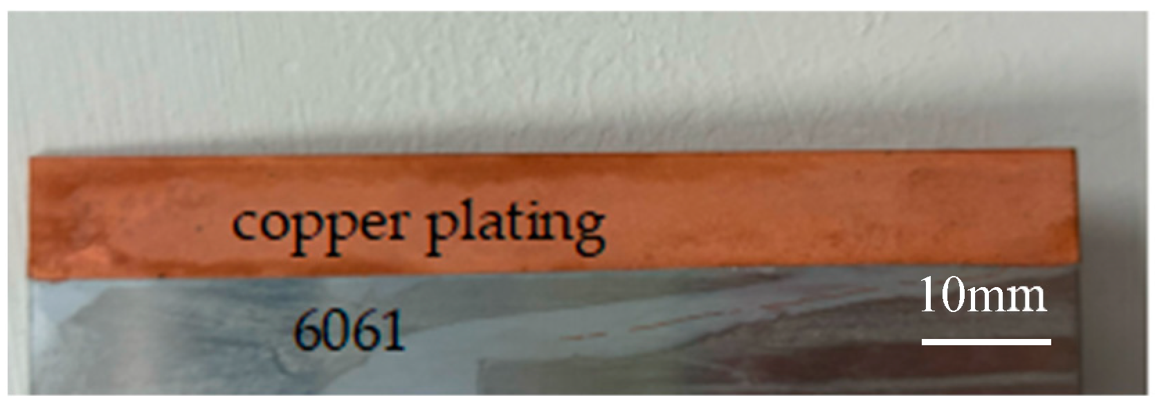
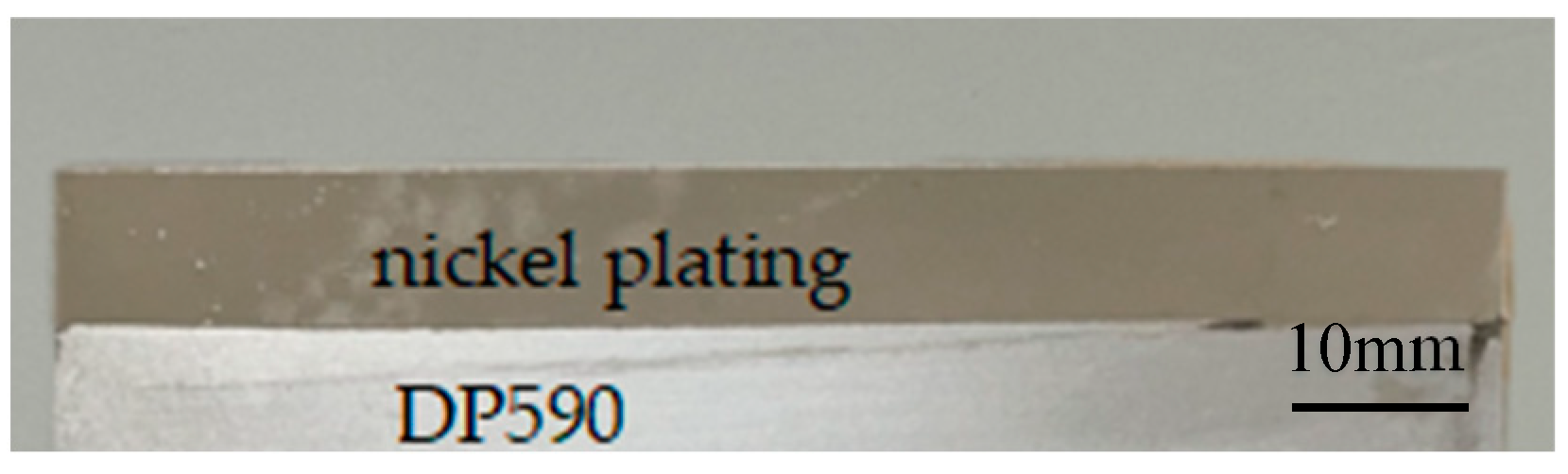
2.3. Pre-Deposited Copper–Nickel Binary Coating

The DP590 dual-phase steel and 6061 aluminum alloy specimens were separately immersed in a nickel chloride electroplating solution and a copper sulphate electroplating solution to apply nickel and copper coatings on the welding zone surfaces. The current density was set to 6 A/dm², and the electroplating durations were 1 h, 2 h, and 3 h. The electroplated samples are shown in Figure 1 and Figure 2.
By varying the electrochemical deposition time to 1 h, 2 h, and 3 h, the resulting thicknesses of the copper and nickel coatings were measured, as shown in Table 3.

2.4. Steel/Aluminum Laser Lap Welding Tests

The laser lap welding experiment was conducted using a lap joint configuration with steel on top and aluminum underneath. Welding was carried out on the pre-coated aluminum–steel dissimilar materials with side-blown shielding gas. The airflow direction formed a 30° angle with the laser beam, as illustrated in Figure 3.
To investigate the effect of the copper–nickel binary coating thickness on the quality of aluminum–steel welds, experiments were conducted with coating thickness as the control variable. A Nd:YAG laser was used as the heat source, with the laser beam positioned perpendicular to the workpiece. The welding speed was set at 100 mm/min, the defocus amount was zero, the single pulse energy was 9 J, the pulse width was fixed at 6 ms, and the frequency was 15 Hz. Additionally, the welding process employed a pulse linear scanning strategy, where the laser beam scanned in a straight-line path. The spot overlap ratio was set to 80%, ensuring stable fusion and reducing defects.

2.5. Quality Assessment of Aluminum–Steel Lap Welds

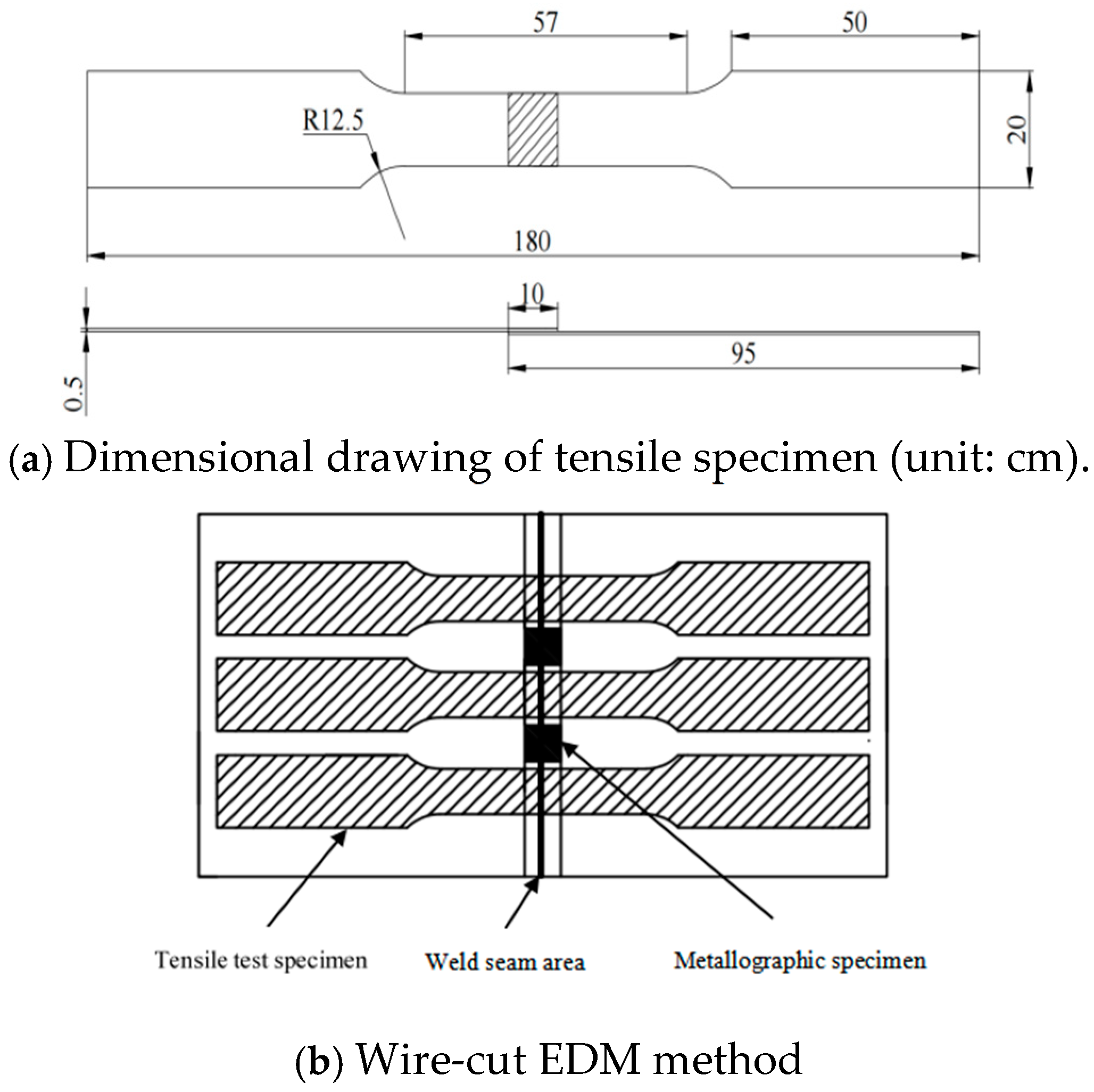
2.5.1. Mechanical Performance Testing

The aluminum–steel lap-welded specimens were fabricated into corresponding tensile test samples in accordance with ASTM E8/E8M-21. Each welded plate was processed using wire-cut electrical discharge machining (EDM) to prepare three sets of tensile test specimens and two metallographic specimens, ensuring statistical reliability. The specific parameters of the tensile test specimens and the wire-cut EDM processing method are shown in Figure 4. Static lap shear tests were conducted at room temperature with a testing speed of 5 mm/min. An electronic universal tensile testing machine (CMT5105, MTS, Orlando, FL, USA) was used to measure the tensile strength of the specimens.

2.5.2. Microstructural Observation

The welded specimens were wire-cut into 10 × 10 × 1 mm samples, followed by cleaning, hot mounting, grinding, and polishing. Metallographic specimens were prepared by etching with Keller’s reagent (95 mL H2O + 2.5 mL HNO3 + 1.5 mL HCl + 1.0 mL HF).
Microstructure observations of the samples were carried out on the samples using a confocal microscope (Axio Scope A1, ZEISS, Oberkochen, Germany) and a scanning electron microscope (S-3400N, Hitachi, Tokyo, Japan). Energy-dispersive X-ray spectroscopy (S-3400N, Hitachi, Japan) was employed to perform line scan analysis of Cu and Ni element distribution across the top, middle, and bottom sections of the weld cross-section. To further investigate the primary composition of compounds in the weld, point scan analysis was conducted on six characteristic regions at the bottom of the weld pool to determine the elemental ratios of Fe, Al, Cu, and Ni.

3. Results and Analysis

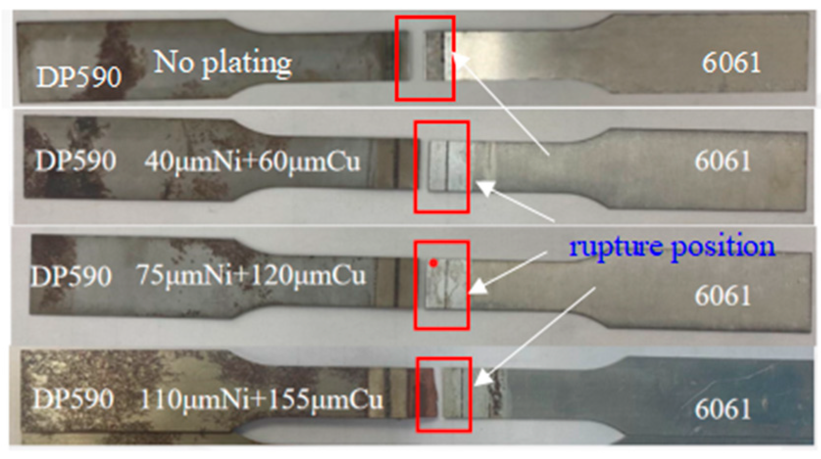
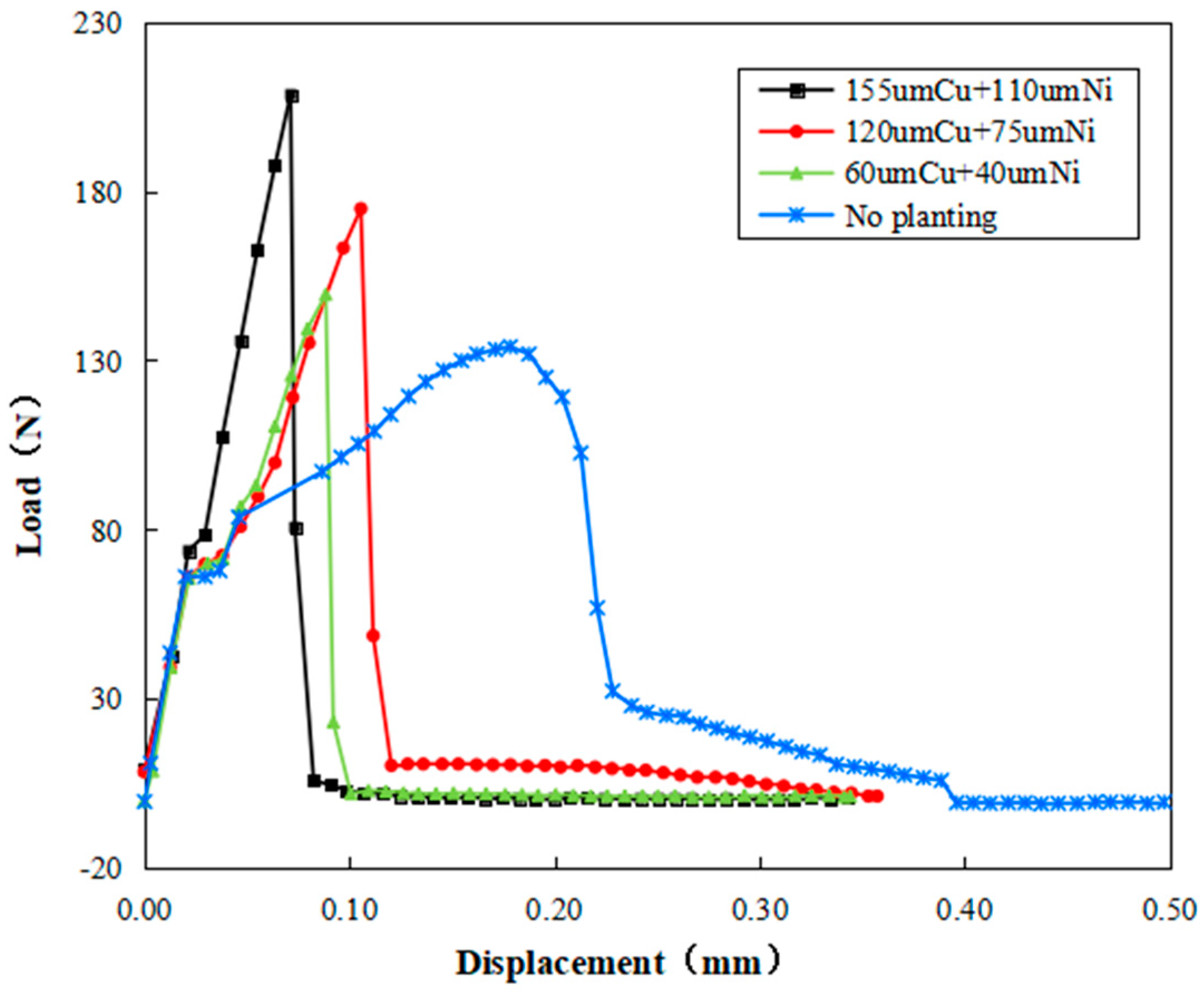
3.1. Mechanical Performance Analysis of Welds

Figure 5 compares the tensile fracture diagrams of aluminum–steel lap welds with no coating and those with different thicknesses of the copper–nickel binary coating. As shown in Figure 5, the fracture locations of all four groups were within the aluminum–steel weld zone, with no damage observed in the base metal. This indicates that the mechanical performance of the welds is lower than that of the aluminum base metal.
Figure 6 presents the load–displacement curves of aluminum–steel lap weld joints with and without coatings. The displacement in Figure 6 refers to the relative movement between the welded materials under applied shear force, typically representing the amount of deformation in the shear direction. The results demonstrate that the shear strength of the welds with coatings was superior to that of the welds without coatings. This improvement is primarily due to the addition of the copper–nickel coating, which inhibited the formation of brittle Fe-Al intermetallic compounds, thus enhancing the mechanical performance of the coated welds. When the thicknesses of the Cu and Ni coatings were 110 μm and 155 μm, respectively, the welds exhibited the highest shear strength, with a maximum shear force of 208 N, corresponding to a shear stress of 205 MPa. In contrast, for welds without coatings, the maximum shear force was 133 N, with a corresponding shear stress of 149 MPa.
The change around 80 N represents the end of the elastic deformation phase and the initiation of fracture. Up to this point, the welds with and without coatings exhibited similar elastic behaviour. However, in the plastic deformation phase, welds with coatings showed a higher ultimate shear strength but lower displacement before fracture, suggesting a trade-off between strength and ductility.
This enhancement is attributed to the increased copper and nickel content in the laser welding molten pool, where Cu and Ni atoms reacted metallurgically with Fe and Al atoms to form ductile compounds containing Cu and Ni. However, excessive coating thickness may promote the formation of additional intermetallics, leading to localized strain accumulation, promoting stress concentration and reducing the overall ductility of the welds. The microstructural heterogeneity introduced by thick coatings could further limit plastic deformation, resulting in early fracture initiation.
Furthermore, a comparison with existing literature on aluminum–steel welding indicates that the shear stress values obtained in this study align with previously reported results. Guo et al. investigated aluminum–steel welded joints using laser welding-brazing with different filler-wire compositions, reporting shear force values ranging from 186 N to 203 N [22]. These values are consistent with the results obtained in this study, where the coated welds exhibited a shear force of 208 N. This comparison confirms the reliability of our experimental results and further highlights the effectiveness of Cu-Ni coatings in enhancing the shear strength of aluminum–steel welds.

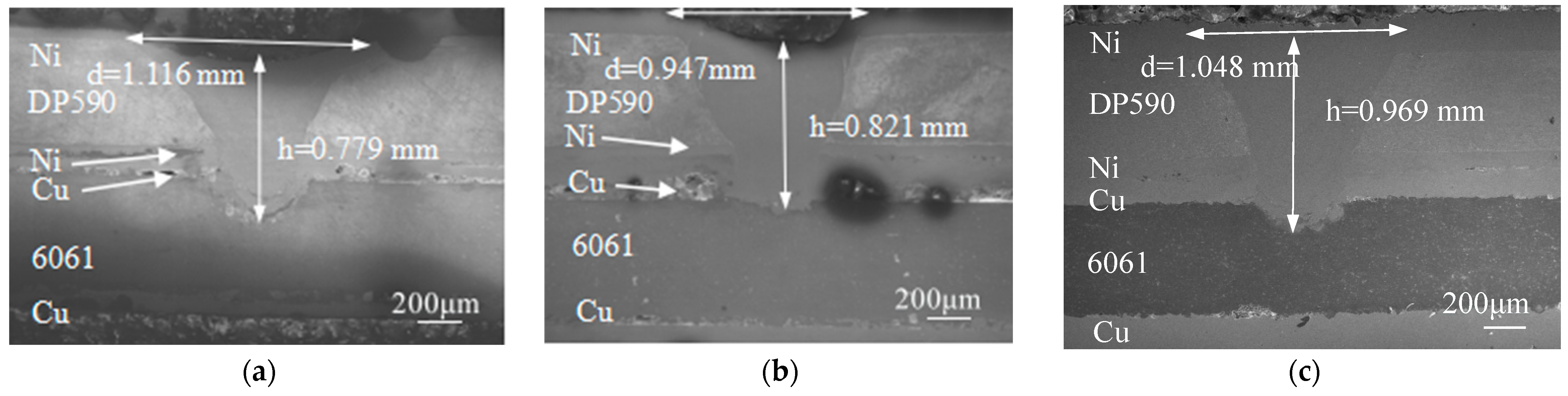
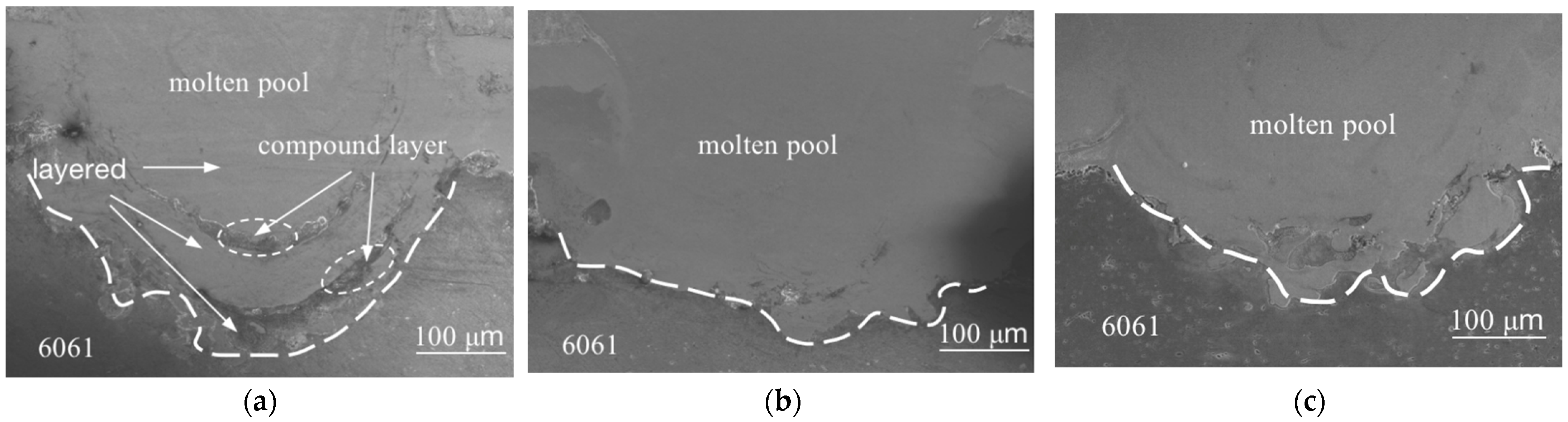
3.2. Morphology Analysis of Welds

Figure 7 shows the cross-sectional morphology of aluminum–steel lap welds with varying thicknesses of copper–nickel binary coatings. When the Cu and Ni coating thicknesses were 60 μm and 40 μm, respectively, the thin intermediate metallic layer allowed residual heat from the melted DP590 dual-phase steel to penetrate the aluminum alloy below, resulting in a weld depth of 0.779 mm and a weld width of 1.116 mm. Significant ablation of the upper weld metal was observed. As the Cu and Ni coating thicknesses increased to 120 μm and 75 μm, respectively, a greater amount of Cu and Ni metal in the weld reduced heat transmission to the lower aluminum layer, leading to a flatter aluminum–steel fusion interface. The weld depth and width were measured at 0.821 mm and 0.947 mm, respectively, with no cracks observed. When the Cu and Ni coating thicknesses were further increased to 155 μm and 110 μm, minimal ablation of the upper weld metal occurred, allowing more heat transfer to the aluminum below. The weld depth reached 0.969 mm, and the weld width was 1.048 mm.
Figure 8 illustrates the weld morphology of aluminum–steel lap joints with varying copper–nickel coating thicknesses. At coating thicknesses of 60 μm for Cu and 40 μm for Ni, the weld fusion line appeared coarse with some stratification in the weld pool. As the coating thickness increased to 120 μm for Cu and 75 μm for Ni, the weld interface morphology improved, becoming tighter and smoother, although the fusion line contour remained irregular. At coating thicknesses of 155 μm for Cu and 110 μm for Ni, the weld interface morphology was optimal, featuring a smooth and compact fusion line, with no cracks observed in the weld pool.
Comparisons revealed that as the coating thickness increased, the weld pool deepened, the morphology of the weld interface improved, stratification in the weld zone disappeared, and the fusion line became smoother and more regular, ultimately forming a “C” shape.

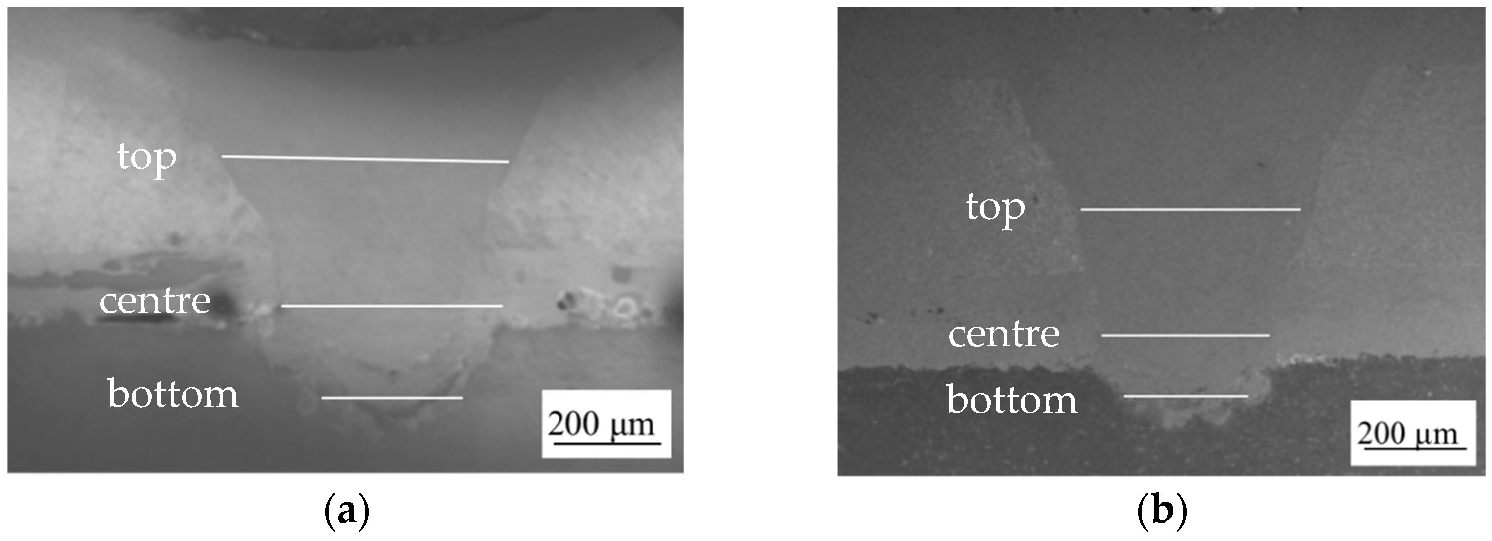
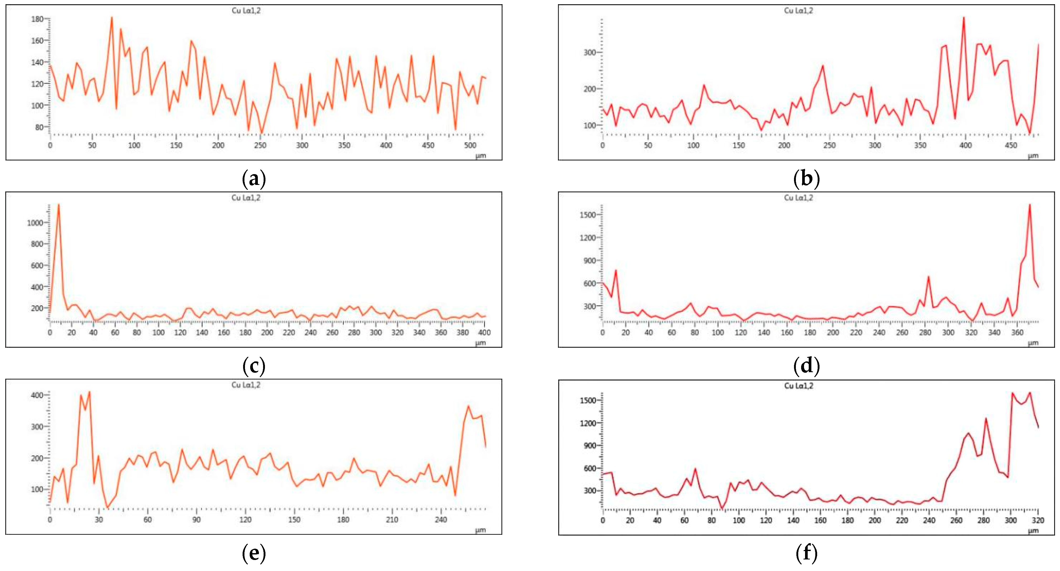
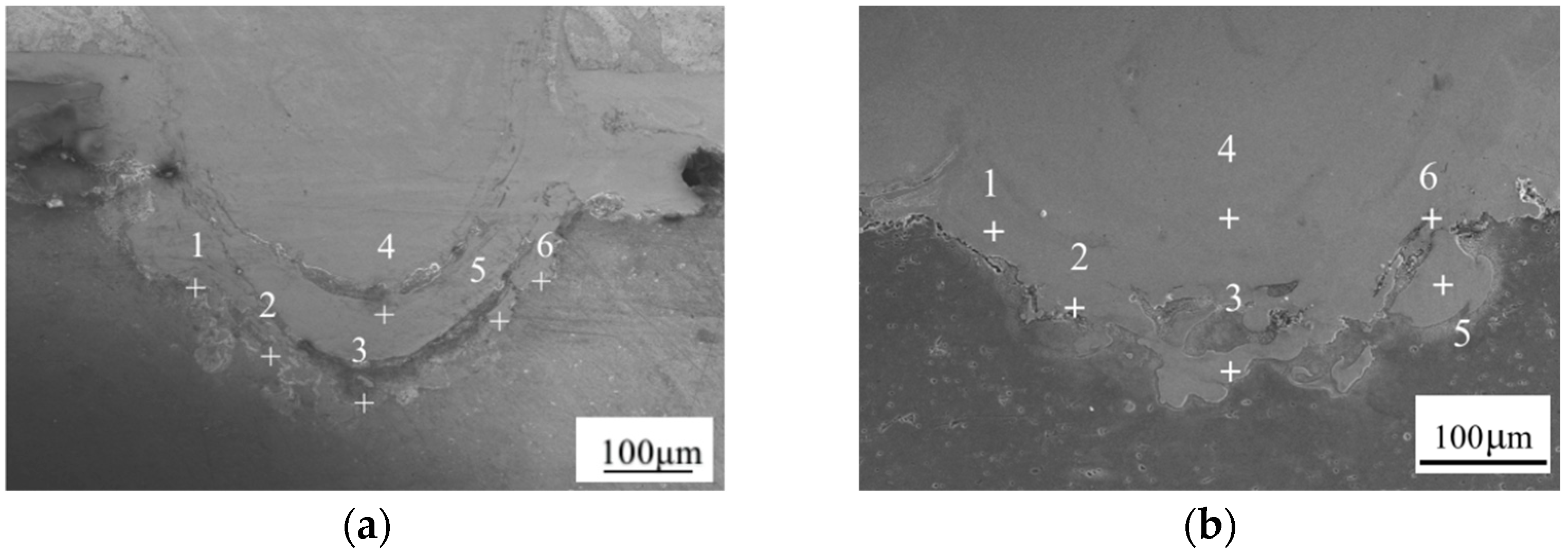
3.3. EDS Line Scan Analysis of Cu and Ni Elements in the Weld

Line scans were performed on the top, centre, and bottom sections of welds with 60 μm Cu + 40 μm Ni and 155 μm Cu + 110 μm Ni coatings. Figure 9 shows the line scan locations.
Figure 10 illustrates the distribution of Cu along the scanning path (X-axis: scan path length in micrometres; Y-axis: intensity of characteristic X-rays in counts per second). The results indicate that Cu was evenly distributed at the top and concentrated near the fusion line in the centre and bottom sections. This suggests that Cu serves as an interlayer, preventing the diffusion of Al atoms toward the steel side and suppressing the formation of brittle Fe-Al intermetallic compounds.
Figure 11 presents the distribution of Ni with the same axis definitions as Figure 10. Compared to Cu, Ni exhibited more uniform diffusion, with significant Ni-rich regions present at the top, centre, and bottom of the weld. This suggests that Ni, having an atomic mass closer to Fe, diffuses more easily into the Fe-rich molten pool regions.

3.4. Compound and Microstructural Analysis of Welds

Based on the EDS line scan analysis, point scans were conducted on six characteristic regions at the bottom of the weld pool in aluminum–steel laser lap welds with varying copper–nickel coating thicknesses, as shown in Figure 12. Points 1, 2, 3, 5, and 6 were located on the fusion line, while Point 4 was at the bottom of the weld pool’s symmetry axis.
The atomic percentages of Al, Fe, Cu, and Ni in these regions are shown in Table 4 and Table 5. For coatings with 60 μm Cu and 40 μm Ni, the atomic percentages of Fe, Cu, Ni, and Al in regions 1, 2, 4, 5, and 6 were observed to be close to but not exactly 3:1, suggesting that these regions may primarily contain (Fe, Cu, Ni)3Al. However, as noted in Table 4, points 1, 4, and 6 exhibit lower Al content than the theoretical stoichiometric ratio. This discrepancy may be attributed to localized variations in elemental diffusion and the presence of other minor intermetallic phases. Therefore, while these regions likely contain (Fe, Cu, Ni)3Al, the presence of other phases cannot be ruled out. To further clarify the composition, additional point scans and phase identification techniques such as XRD will be considered in future studies. In region 3, the atomic percentage of Fe, Cu, Ni, and Al was approximately 1:3, indicating the presence of (Fe, Cu, Ni)Al3. For coatings with 155 μm Cu and 110 μm Ni, regions 1, 3, 4, 5, and 6 were expected to be dominated by (Fe, Cu, Ni)3Al; however, deviations in Al content were observed, particularly at points 1, 3, and 4 in Table 5. This may be due to the preferential diffusion of Fe and Ni in the molten pool, altering the expected composition. Given these variations, it is possible that some areas contain a mixture of (Fe, Cu, Ni)3 Al and other Fe-rich intermetallic phases rather than a single uniform phase. Future research will focus on a more comprehensive phase analysis to better understand the influence of Cu and Ni additions on phase formation. Meanwhile, region 2 exhibited a Cu:Al ratio of 1:5, suggesting the formation of CuAl5, which further supports the role of Cu in modifying the weld microstructure.
Comparisons revealed that at 60 μm Cu + 40 μm Ni, the Cu and Ni layers reacted with Al atoms to form (Fe, Cu, Ni)3Al and similar compounds. This reaction prevented Al atoms from diffusing toward the Fe side, reducing the formation of brittle Fe-Al intermetallic compounds and thus improving weld quality. As the coating thickness increased to 155 μm Cu + 110 μm Ni, the atomic percentages of Cu and Ni in the weld zone further increased. More Cu and Ni atoms reacted with Al atoms, further hindering Al diffusion and enhancing the overall weld quality.

4. Conclusions

In this study, on aluminum–steel laser welding, a pre-deposited copper–nickel binary coating was used as an interlayer. Through tensile tests and microscopic analysis, the effects of the copper–nickel binary coating thickness on the mechanical performance, morphology, microstructure, and compound composition of the welds were investigated. The main conclusions are as follows:
1
The pre-deposition of a copper–nickel binary coating between aluminum and steel significantly improved the weld quality in aluminum–steel laser lap welding. It reduced the formation of cracks in the weld zone, resulted in a smoother fusion line interface, and greatly enhanced the mechanical performance of the welds. The weld exhibited optimal shear strength when the Cu and Ni coating thicknesses were 155 μm and 110 μm, respectively, achieving a maximum shear force of 208.09 N, which represents a 56% improvement compared to aluminum–steel lap welding without coatings.
2
As the thickness of the copper–nickel binary coating increased, more Cu and Ni atoms entered the molten pool and reacted metallurgically with Fe and Al atoms, forming multi-element compounds such as (Fe, Cu, Ni)3Al, (Fe, Cu, Ni)Al3, and CuAl5. This effectively suppressed the formation of brittle Fe-Al intermetallic compounds, further enhancing the weld quality.

Author Contributions

Conceptualization, H.Z. and H.G.; methodology, H.Z. and D.M.; investigation, H.Z. and H.G.; resources, D.M.; data curation, H.G.; writing—original draft preparation, H.G.; writing—review and editing, H.Z.; project administration, H.Z.; funding acquisition, H.Z. All authors have read and agreed to the published version of the manuscript.

Funding

This research was funded by “National Natural Science Foundation of China, grant number 51205212” and “Postgraduate Research & Practice Innovation Program of Jiangsu Province grant number KYCX233389” and “Basic Research Program of Nantong grant number JC22022074”.

Data Availability Statement

The authors confirm that the data supporting the findings of this study are available within the article.

Conflicts of Interest

The authors declare no conflicts of interest.

References

  1. Schimek, M.; Springer, A.; Kaierle, S.; Kracht, D.; Wesling, V. Laser-welded dissimilar steel-aluminum seams for automotive lightweight construction. Phys. Procedia 2012, 39, 43–50. [Google Scholar]
  2. Wu, X.; Yan, H.; Zhou, Y.; Zhang, P.; Lu, Q.; Shi, H. Review of additive manufactured metallic metamaterials: Design, fabrication, property and application. Opt. Laser Technol. 2025, 182, 112066. [Google Scholar]
  3. Li, J.; Sun, Q.; Jia, J.; Zhu, W. Research on Pre-Compensation and Shape-Control Optimization of Hemming Structures with Dissimilar Materials Based on Forming Process Chain. Metals 2024, 14, 1063. [Google Scholar] [CrossRef]
  4. Marumoto, K.; Horai, T.; Morita, D.; Oda, C.; Fujii, T.; Yuzawa, T.; Koba, R.; Yamamoto, M. Development of Hot-Wire Laser Additive Manufacturing for Dissimilar Materials of Stainless Steel/Aluminum Alloys. J. Manuf. Mater. Process. 2024, 8, 93. [Google Scholar] [CrossRef]
  5. Wallerstein, D.; Salminen, A.; Lusquinos, F.; Comesaa, R.; Pou, J. Recent developments in laser welding of aluminum alloys to steel. Metals 2021, 11, 622. [Google Scholar] [CrossRef]
  6. Wu, L.; Oliveira, J.; Yang, J.; Xiao, M.; Zheng, M.; Xu, W.; Zhao, Y.; Wang, F.; Zhang, H. Effect of Al-Si Coating on the Interfacial Microstructure and Corrosion Resistance of Dissimilar Laser Al Alloy/22MnB5 Steel Joints. Metals 2024, 14, 328. [Google Scholar] [CrossRef]
  7. Jiang, F.; Wang, W.; Zhang, X.; Gong, W. Microstructure and Mechanical Properties of Friction Stir Lap Welding Joint of Al/CU Dissimilar Metals. Metals 2023, 13, 1969. [Google Scholar] [CrossRef]
  8. Shi, X.; Zhang, S.; Li, T.; Meng, X.; Cheng, C.; Pei, J.; Cao, T.; Zhao, J. Corrosion Behavior and Mechanical Property of 5182 Aluminum/DP780 Steel Resistance Spot Welding Joints. Materials 2024, 17, 2472. [Google Scholar] [CrossRef]
  9. Zhao, Y.; Long, Y.; Li, Z. Research progress of transition layer and filler wire for laser welding of steel and aluminum dissimilar metals. Int. J. Adv. Manuf. Technol. 2022, 119, 4149. [Google Scholar]
  10. Li, Y.; Liu, Y.; Yang, J. First principle calculations and mechanical properties of the intermetallic compounds in a laser welded steel/aluminum joint. Opt. Laser Technol. 2020, 122, 105875. [Google Scholar]
  11. Yang, J.; Su, J.; Gao, C.; Zhao, Y.; Liu, H.; Joao, P.; Tan, C.; Yu, Z. Effect of heat input on interfacial microstructure, tensile and bending properties of dissimilar Al/steel lap joints by laser Welding-brazing. Opt. Laser Technol. 2021, 142, 107218. [Google Scholar]
  12. Yu, J.; Fan, Y.; Zhang, H.; Cao, W.; Zhang, H.; Su, Z.; Gao, J. Interfacial evolution of thermo-compensated resistance diffusion welding of Al/steel joint with Ni interlayer via resistance seam welding. J. Mater. Eng. Perform. 2024, 33, 6480. [Google Scholar]
  13. Jiang, Q.; Yang, J.; Xiao, R.; Zheng, M.; Jiang, J.; Xue, J.; Xu, W.; Xu, J.; Zhang, H. Outstanding ductility of dissimilar laser Al/steel spot joint using a high entropy alloy interlayer. Mater. Lett. 2023, 349, 134707. [Google Scholar]
  14. Hu, X.; Xia, C.; Zhang, H.; Wan, G.; Liu, S.; Long, W. The microstructure and mechanical properties of aluminum/steel welded joint with Ni foil interlayers by FSLW. J. Adhes. Sci. Technol. 2024, 38, 1413. [Google Scholar]
  15. Li, B.; Han, S.; Ao, W.; Yang, Y.; Liu, D. Investigation on microstructure and mechanical properties of the dissimilar lap welding of Al alloy to steel with different filler materials and laser powers. Int. J. Adv. Manuf. Technol. 2024, 134, 935. [Google Scholar]
  16. Esmaily, H.; Habibolahzadeh, A.; Tajally, M. Improving pulsed laser weldability of duplex stainless steel to 5456 aluminum alloy via friction stir process reinforcing of aluminum by BNi-2 brazing alloy. Trans. Nonferrous Met. Soc. China 2019, 29, 1401. [Google Scholar]
  17. Yu, G.; Chen, S.; Zhao, Z.; Wen, Z.; Huang, J.; Yang, J.; Chen, S. Comparative study of laser swelding-brazing of aluminum alloy to galvanized steel butted joints using five different filler wires. Opt. Laser Technol. 2022, 147, 107618. [Google Scholar]
  18. Hu, Y.; Zhang, Y.; Mi, G.; Wang, C.; Zhang, W.; Zhang, X. Effects of Si contents in filling wires on microstructure evolution and properties of Al-steel dissimilar joint by laser welding-brazing. J. Mater. Res. Technol. 2021, 15, 1896–1904. [Google Scholar]
  19. Shi, Y.; Li, Z.; Yin, C.; Yu, X.; Kou, Y. Effect of alloying elements Cu and Ni on mechanical properties of steel/aluminum laser welded joints. Optik 2022, 255, 168707. [Google Scholar]
  20. Zhang, Y.; Wang, W.; Li, Z.; Huang, G.; Zhang, H.; Liu, F. Study of the brittleness mechanism of aluminum/steel laser welded joints with copper and vanadium interlayers. Opt. Laser Technol. 2023, 163, 109319. [Google Scholar]
  21. Li, T.; Zhou, D.; Yan, Y.; Liu, J. Effect of laser-Ti foil coupling on microstructure and mechanical property of steel/aluminum fusion welding joints. Opt. Laser Technol. 2021, 141, 107114. [Google Scholar]
  22. Guo, W.; Wu, M.; Teng, L.; Liu, L.; Wan, H. Effect of Filler-Wire Composition on Microstructure and Properties of Al/Steel-Welded Joints by Laser Welding–Brazing. Crystals 2025, 15, 266. [Google Scholar] [CrossRef]
Figure 1. Copper-plated 6061 aluminum alloy specimen.
Crystals 15 00300 g001
Figure 2. Nickel-plated DP590 dual-phase steel specimen.
Crystals 15 00300 g002
Figure 3. Schematic diagram of laser welding.
Crystals 15 00300 g003
Figure 4. Dimensional drawing of tensile specimen and wire-cut EDM method.
Crystals 15 00300 g004
Figure 5. Tensile fracture of joints without plating and with different thicknesses of coating.
Crystals 15 00300 g005
Figure 6. Tensile-shear load–displacement curves of joints without plating and with different thicknesses of plating.
Crystals 15 00300 g006
Figure 7. Cross-sectional morphology of welds in aluminum–steel lap welds with different thicknesses of preformed Cu-Ni binary coatings: (a) 60 μm Cu + 40 μm Ni; (b) 120 μm Cu + 75 μm Ni; (c) 155 μm Cu + 110 μm Ni.
Crystals 15 00300 g007
Figure 8. Weld morphology of aluminum–steel lap welds with different thicknesses of copper–nickel binary plating preformed: (a) 60 μm Cu + 40 μm Ni; (b) 120 μm Cu + 75 μm Ni; (c) 155 μm Cu + 110 μm Ni.
Crystals 15 00300 g008
Figure 9. Weld line scanning position of the welded joint with different thicknesses of copper–nickel binary plating preformed: (a) 60 μm Cu + 40 μm Ni; (b) 155 μm Cu + 110 μm Ni.
Crystals 15 00300 g009
Figure 10. Cu element distribution in different section of welds with different copper–nickel binary: (a) top section of 60 μm Cu + 40 μm Ni weld; (b) top section of 155 μm Cu + 110 μm Ni weld; (c) centre section of 60 μm Cu + 40 μm Ni weld; (d) centre section of 155 μm Cu + 110 μm Ni weld; (e) bottom section of 60 μm Cu + 40 μm Ni weld; (f) bottom section of 155 μm Cu + 110 μm Ni weld.
Crystals 15 00300 g010
Figure 11. Ni element distribution in different section of welds with different copper–nickel binary: (a) top section of 60 μm Cu + 40 μm Ni weld; (b) top section of 155 μm Cu + 110 μm Ni weld; (c) centre section of 60 μm Cu + 40 μm Ni weld; (d) centre section of 155 μm Cu + 110 μm Ni weld; (e) bottom section of 60 μm Cu + 40 μm Ni weld; (f) bottom section of 155 μm Cu + 110 μm Ni weld.
Crystals 15 00300 g011
Figure 12. Scanning positions for EDS analysis of welds with different thicknesses of plated layers: (a) 60 μm Cu + 40 μm Ni; (b) 155 μm Cu + 110 μm Ni.
Crystals 15 00300 g012
Table 1. Chemical composition of DP 590 (mass score/%).
MaterialCMnPSiNiSCrFe
DP5900.1502.5000.0400.600-0.0150.020Bal.
Table 2. Chemical composition of 6061 aluminum alloy (mass score/%).
MaterialCuMnMgZnCrTiSiFeAl
60610.150.150.80.250.040.150.40.7Bal.
Table 3. Thickness variation of copper–nickel binary plating at different times.
Serial NumberTime (h)Cu Coating Thickness (μm)Ni Coating Thickness (μm)
116040
2212075
33155110
Table 4. EDS compositional analysis of welds at 60 μm Cu + 40 μm Ni (atomic fraction, %).
PlacementAl (at%)Fe (at%)Cu (at%)Ni (at%)Polymetallic Phase (Chemistry)
114.4468.033.4214.11(Fe, Cu, Ni)3Al
221.0563.53.0512.4(Fe, Cu, Ni)3Al
376.0417.312.614.04(Fe, Cu, Ni)Al3
413.3170.355.9510.39(Fe, Cu, Ni)3Al
520.1159.368.7511.78(Fe, Cu, Ni)3Al
612.6363.5810.0313.76(Fe, Cu, Ni)3Al
Table 5. EDS compositional analysis of welds at 155 μm Cu + 110 μm Ni (atomic fraction, %).
PlacementAl (at%)Fe (at%)Cu (at%)Ni (at%)Polymetallic Phase (Chemistry)
110.0961.0512.1216.74(Fe, Cu, Ni)3Al
285.81014.050.14CuAl5
312.5245.2912.9529.24(Fe, Cu, Ni)3 Al
47.2957.568.1327.02(Fe, Cu, Ni)3Al
517.2534.9926.7321.03(Fe, Cu, Ni)3Al
620.1941.708.3529.76(Fe, Cu, Ni)3Al
Disclaimer/Publisher’s Note: The statements, opinions and data contained in all publications are solely those of the individual author(s) and contributor(s) and not of MDPI and/or the editor(s). MDPI and/or the editor(s) disclaim responsibility for any injury to people or property resulting from any ideas, methods, instructions or products referred to in the content.

