Abstract
This study investigates the mesostructural damage evolution and creep deformation mechanisms in bedded rock salt through integrated scanning electron microscopy (SEM) and multistage creep experiments. Utilizing a self-developed in situ observation system coupled with digital image correlation (DIC) analysis, the microstructural heterogeneity, strain localization, and damage propagation patterns in the rock were systematically characterized. The results revealed distinct microstructural contrasts between rock salt and argillaceous interlayers, with interfacial regions exhibiting pore-rich, interconnected structures due to crystal gradation disparities. Creep damage initiation predominantly occurred in pure rock salt domains, manifesting as transgranular fractures and intercrystalline slip, followed by crack propagation into salt–mudstone interfaces governed by shear dilatancy. The integration of mesoscale structural characterization with macroscopic mechanical behavior establishes a framework for predicting the long-term stability of bedded salt formations under operational loads.
1. Introduction
Owing to its exceptional mechanical properties, low permeability, and distinctive creep behavior, rock salt has emerged as a preferred geological medium for underground space development and energy storage applications, widely recognized as the optimal host material for subsurface reservoirs [1,2]. However, laminated rock salt exhibits markedly different mechanical and interfacial behaviors compared to homogeneous rock salt due to the presence of interlayers, contrasts in physical properties, and inherent heterogeneity. The increasing deployment of deeper reservoirs and increasingly complex storage environments further complicate the interplay between mesostructural evolution and creep deformation in laminated rock salt [3,4]. Consequently, establishing correlations between microscale to mesoscale structural evolution and creep-induced damage mechanisms is crucial for understanding the deformation and failure characteristics of laminated rock salt.
Current research on the microstructural evolution of laminated rock salt primarily employs scanning electron microscopy (SEM) [5,6,7], X-ray computed tomography (CT) [8,9], and nuclear magnetic resonance (NMR) [10] for microstructural characterization. In studies by Liang et al. [11], Vandeginste et al. [12], and Liu et al. [13], SEM analyses revealed predominantly crystalline microstructures with well-defined interfacial boundaries and compact polycrystalline arrangements, forming discontinuous multi-crystalline structures. In contrast, argillaceous interlayers exhibit flaky or scaly morphologies, primarily composed of clay minerals [14]. The interfacial structures are characterized by randomly distributed mudstone and other mineral fillings within the salt matrix [15]. Additionally, investigations using transmitted light imaging techniques have provided further insights into the micro-morphological features of laminated rock salt [16]. Notably, Martin et al. [17] identified through CT analysis that interfacial regions contain abundant illite, quartz, and gypsum, with clay minerals aggregating around larger salt crystals in an intermixed configuration. The microstructural heterogeneity of laminated rock salt induces variations in micromechanical properties, leading to complex damage evolution mechanisms [18,19]. Gelencsér et al. [20] established correlations between rock salt microstructure and deformation behavior, particularly intracrystalline plastic deformation. The reduced microstress in laminated rock salt grains, compared to massive rock salt, is attributed to diminished intercrystalline bonding strength resulting from the distinct physico-mechanical properties of salt and clay components, promoting dislocation generation and slip phenomena under loading [21]. Current research primarily focuses on separately analyzing microstructural characteristics and micromechanical properties, with limited integration of microstructural damage evolution and macroscopic mechanical performance in laminated rock salt. Investigating the microstructural characteristics of laminated rock salt allows a more precise analysis of its evolutionary mechanisms, offering critical insights into its mechanical behavior in research on rock mechanics.
Significant progress has been made in understanding the long-term mechanical behavior of laminated rock salt through creep experimentation, particularly regarding damage evolution, creep characteristics, and microcrack propagation. Research indicates that creep damage mechanisms involve intercrystalline slip, microcrack propagation, and shear dilation, with failure modes manifesting as crystal fracture and slip at the microscale, transitioning to dilatancy-induced damage in rock salt and tensile failure in argillaceous interlayers at the macroscopic scale [22,23,24]. Key influencing factors include temperature, stress levels, and impurity content, with increased clay content significantly affecting deformation magnitude and strength reduction [25,26]. Zhao et al. [27] experimentally demonstrated the low bearing capacity and time-dependent strength degradation of argillaceous interlayers during creep. A higher clay content reduces creep strain while increasing the creep rate, reflecting rheological disparities between brittle and ductile constituents: the material exhibits viscoelastic behavior below the yield stress and viscoplastic responses beyond it [28,29,30]. Microcrack propagation in laminated rock salt is governed by clay content and damage accumulation [31]. The presence of interlayers induces permeability anisotropy, with permeability being higher parallel to bedding planes than in perpendicular orientations [32]. Post-damage permeability increases significantly due to microfracture development in interlayers [33,34,35]. These advancements provide valuable methodologies for investigating creep damage and microcrack propagation, offering critical insights for sealing integrity assessments in rock salt gas storage reservoirs. Successful case studies provide methodological references for advancing research on creep damage and microcracking in laminated rock salt. Further analysis of creep damage mechanisms and structural evolution patterns is expected to drive breakthroughs in sealing integrity studies for salt cavern gas storage systems.
This study employs electron microscopy and creep testing to investigate the microstructural characteristics and damage evolution of laminated rock salt. By integrating electron microscopy findings with creep curves and strain contour maps, the research aims to elucidate the microstructural features and creep damage mechanisms of laminated rock salt. A comprehensive understanding of microstructural aspects is essential for elucidating how internal architectures and compositions influence macroscopic mechanical properties in rock mechanics. The analysis of microstructural evolution characteristics in bedded rock salt proves critical for deciphering macroscopic structural instability mechanisms, which manifest as interfacial slippage and interlayer fractures—phenomena directly linked to potential instability in underground gas storage facilities. Furthermore, investigation of the creep behavior in bedded rock salt assumes particular significance for evaluating its long-term stability under sustained loading conditions. Through systematic examination of microstructural evolution patterns, this research ultimately reveals fundamental mechanisms governing interfacial slippage and dislocation processes in bedded salt formations.
2. Experimental Methodology
To investigate the mesostructural and damage evolution characteristics of bedded rock salt under creep deformation, this study employed scanning electron microscopy (SEM) to analyze and compare the microstructural features of salt, impurities, and salt–mudstone interfaces.
A self-developed in situ observation device was utilized to monitor mesostructural damage during creep deformation. The experimental materials, apparatus, and procedures are detailed in the following subsections.
2.1. Experiment Materials
The formation primarily consists of interbedded rock salt, mudstone, and gypsum-bearing mudstone, with NaCl content typically ranging from 70 to 90% and content ranging from 3 to 7%.
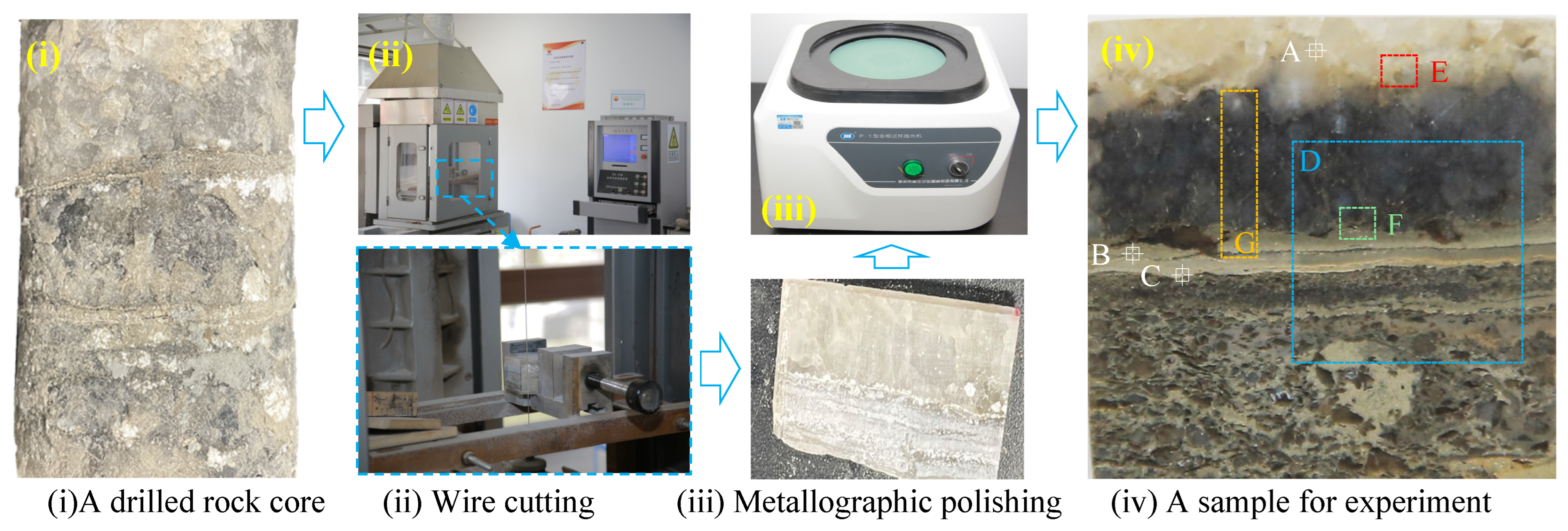
A core sample of typical bedded rock salt, characterized by two distinct interlayers [36], was selected for specimen preparation, as illustrated in Figure 1. A wire-cutting apparatus equipped with a 0.5 mm diameter diamond-coated wire was used to ensure precise sample fabrication. To minimize thermal damage during cutting, a controlled cutting speed of 10 m/min was maintained. The prepared thin section, measuring approximately 30 mm in length, 30 mm in width, and 5 mm in thickness, was subsequently polished using a metallographic polishing machine, yielding a sample suitable for both SEM analysis and creep deformation experiments.
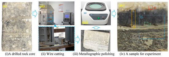
Figure 1.
The procedure for experimental sample preparation.
2.2. Experimental Apparatus
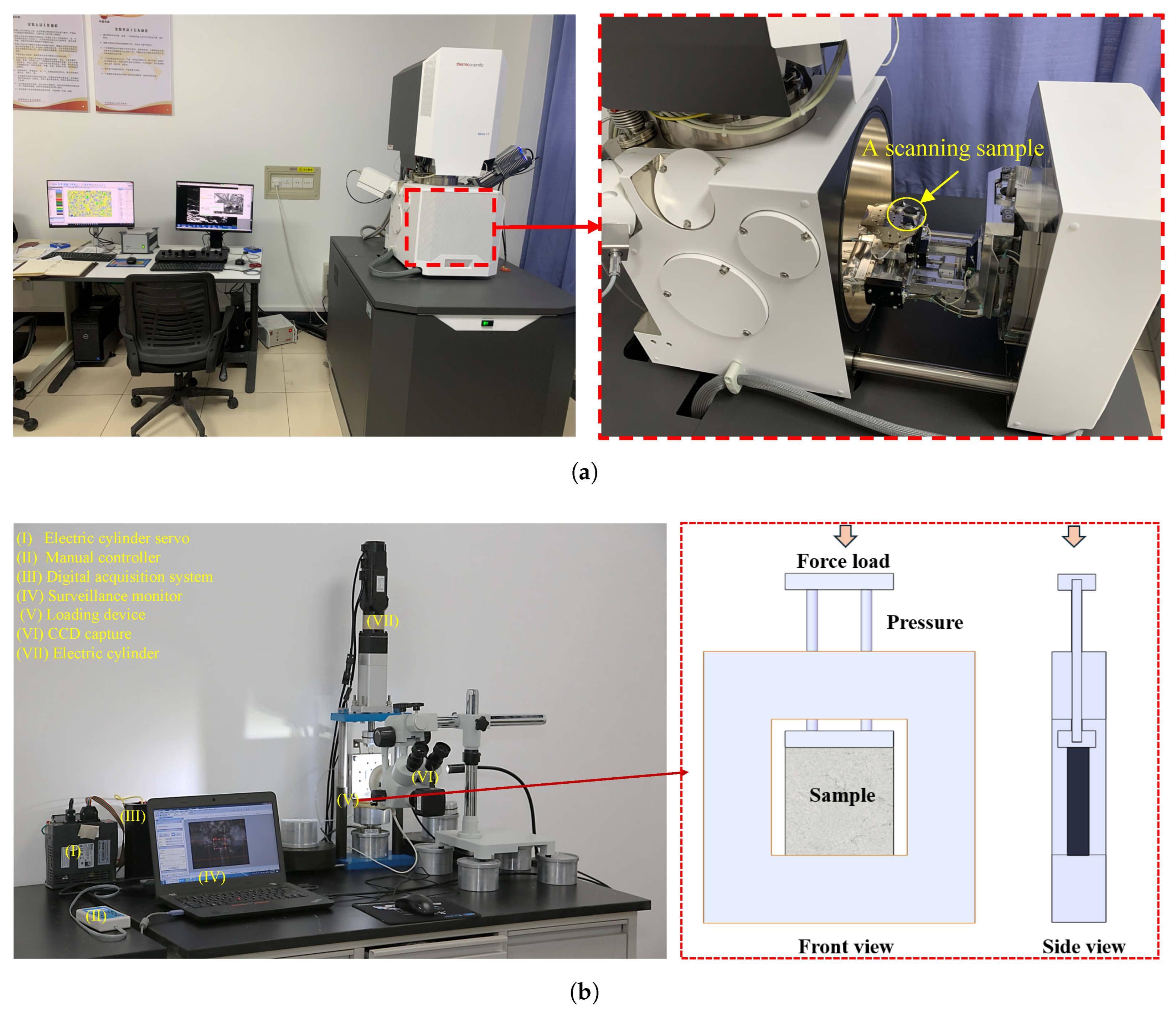
To capture the in situ damage process occurring in the bedded rock salt, a self-developed observation system was integrated into the creep experiment. The loading system operates within a capacity range of 1–10 kN, with a program-controlled loading speed adaptable to both stress- and strain-controlled modes. During creep loading, stress and displacement were recorded using a stress sensor and a linear variable differential transformer (LVDT), with data acquisition managed by the system for subsequent analysis. The stress sensor has a measurement range of 50 kN, while the axial displacement sensor operates within a range of −2.5 mm to 12.5 mm, with a measurement accuracy of 0.5% RO (Taizhou quantum electronic Technology-PM11). Additionally, as shown in Figure 2b, a CCD camera was employed to assess the size, shape, color, and positional characteristics of the observed target. The accompanying image capture software enabled periodic image acquisition at 5 min intervals, with a resolution of 3840 × 2160 pixels.
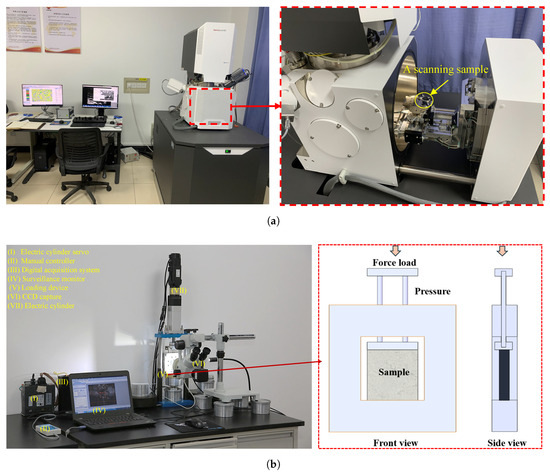
Figure 2.
The experiment apparatus of (a) a field emission SEM and (b) a self-developed system for observing creep loading.
2.3. Experimental Procedures
As depicted in image (iv) of Figure 1, three regions (designated as points A, B, and C) were selected for SEM analysis. The SEM observations captured not only the microstructural features of these areas but also their energy spectra. Prior to imaging, the sample surface was cleaned with a wool brush for 5 min and coated with a thin gold layer using an ion sputtering device to enhance observation quality [37].
A multistage creep loading protocol was applied in the experiment. Based on prior uniaxial compression tests, the compressive strength of the tested sample was determined to be approximately 28.6 MPa. Consequently, the creep stress level for each stage was set at 30% of this value, corresponding to approximately 8.58 MPa. Each creep stage lasted for 12 h. Throughout the experiment, axial displacement data were continuously recorded, while field displacement and damage conditions were documented using the CCD camera [37]. The CCD camera remained fixed at a designated location on the sample (area D in image (iv) of Figure 1), enabling strain evolution analysis via the digital image correlation (DIC) method. The full-field displacement and strain characteristics of layered rock salt were quantified using digital image correlation (DIC) software, with subsequent results subjected to visualization and post-processing in ParaView for enhanced data interpretation.
3. Analysis of Experimental Results
Based on the experimental results, the microstructural characteristics, mesostructural creep deformation, and structural damage evolution of bedded rock salt are analyzed in the following subsections.
3.1. Microstructure and Mineral Composition Analysis of Layered Rock Salt
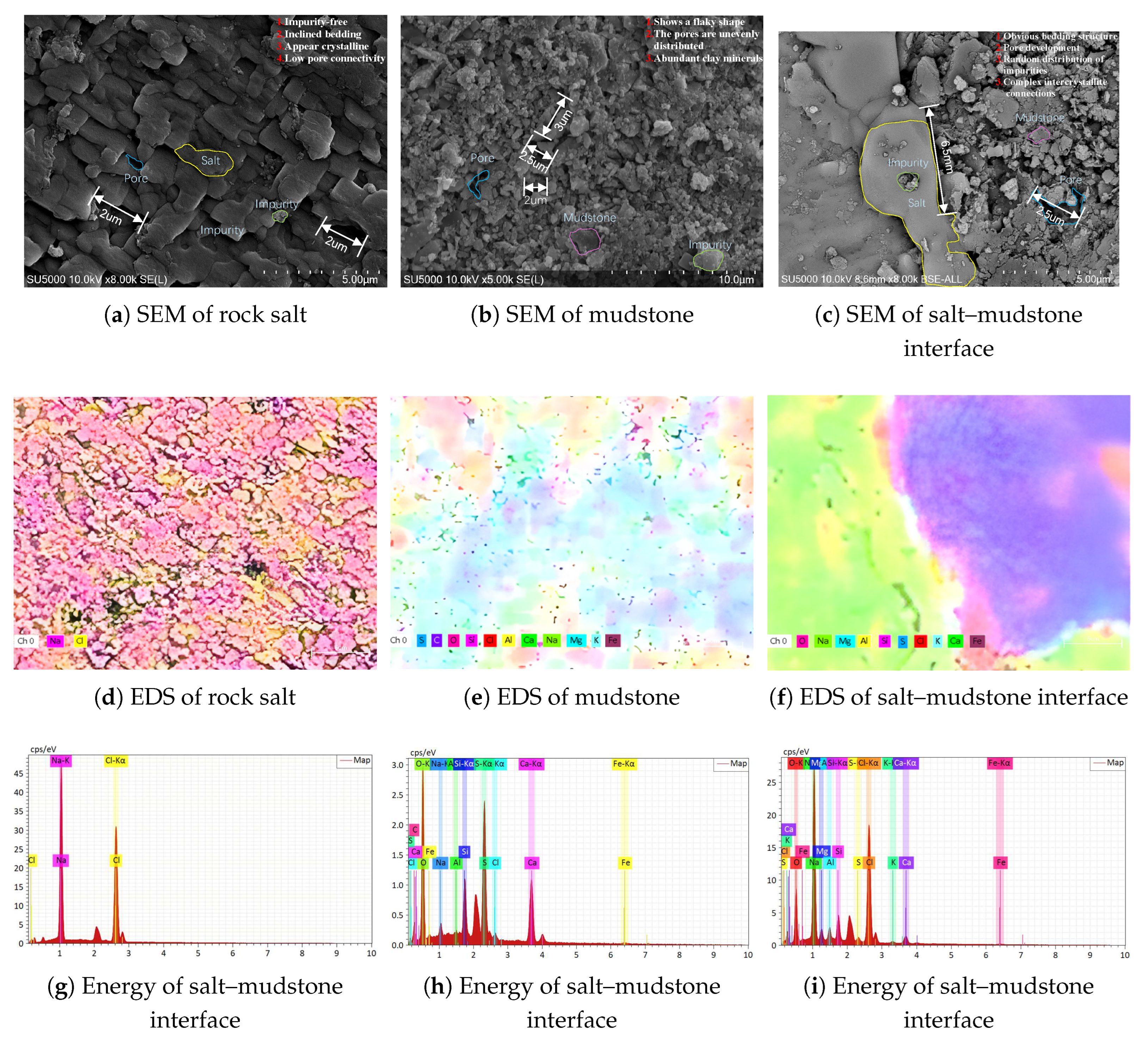
The SEM images of points A, B, and C (corresponding to the marked locations in image (iv) of Figure 1) are presented in Figure 3a–c, respectively. Figure 3d–f display the energy spectra corresponding to Figure 3a–c.
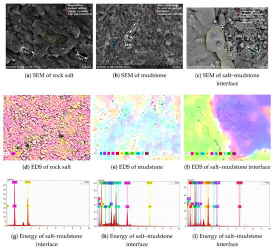
Figure 3.
The SEM results of (a–c) at points A to C in the picture (iv) of Figure 1 and the energy spectrum of (d–f) corresponding to the area of (a–c), respectively.
The energy spectrum in Figure 3d reveals that the scanned region at point A primarily consists of Na and Cl, indicating a zone of relatively pure rock salt. At point B, as shown in Figure 3e, the identified elements include S, C, O, Si, Cl, Al, Ca, Na, Mg, K, and Fe, representing a mixture of mudstone and embedded salt crystals. The spectrum at point C (Figure 3f) exhibits a distinct separation of Na, K, and Cl from Mg, Si, Ca, S, and O, indicative of a typical salt–mudstone interface. Notably, in the salt region adjacent to the mudstone, additional crystal inclusions are observed, with Al, Ca, and O exhibiting a random distribution.
The primary components of pure rock salt are sodium chloride and potassium chloride. In its ideal state, rock salt exhibits a cubic crystal structure [38]. As shown in Figure 3a, rock salt crystals display well-defined cubic shapes with distinct edges, clear interfaces, and close intergranular contact. However, due to geological deposition and other influencing factors, crystal defects such as dislocations and vacancies are present. These defects significantly affect the mechanical properties and stability of the rock salt.
Mudstone primarily forms through the deposition of fine clay mineral particles. Its mineral composition predominantly includes kaolinite, montmorillonite, and illite [39]. In Figure 3b, mudstone exhibits a fine flaky or fibrous microstructure, featuring both primary pores and secondary voids. The pore sizes range from 0.2 µm to 0.3 µm, with an interconnected internal pore network that facilitates fluid infiltration and storage. The surface of mudstone often displays a distinct layered structure, where each layer consists of fine mineral particles with variations in composition and pore structure.
Notably, the interface structure of bedded rock salt exhibits a pronounced layered arrangement [40], as illustrated in Figure 3c. The interfaces between layers are clearly defined and may either be relatively smooth or exhibit undulating irregularities. Due to differences in grain size and morphology between rock salt and mudstone, the grading during the deposition process is imperfect. This results in intermixing of salt and mud, leading to pronounced heterogeneity in particle size and shape. Consequently, the interface and transition zones develop extensive porosity, with complex pore structures and high connectivity. The pore sizes within these zones range from 1 µm to 6.5 µm, with larger pores predominantly concentrated at the interfaces. The primary cause of this phenomenon is the variation in grain size and structure between rock salt and mudstone, which promotes pore development at their interfaces.
Table 1 presents the results of micro-energy-dispersive spectroscopy (EDS) analysis, revealing distinct elemental partitioning among rock salt, mudstone, and their interfacial zones. Rock salt is predominantly composed of Na and Cl, whereas Ca is the principal component in mudstone. At the salt–mudstone interface, Na and Cl remain dominant but exhibit reduced concentrations compared to pure rock salt. In contrast, Mg, Ca, and Si display intermediate concentrations, bridging the compositional differences between rock salt and mudstone.

Table 1.
Elemental mass distribution characteristics of rock salt, mudstone, and the salt–mudstone interface.
Overall, salt crystals within pure rock salt are regularly arranged, whereas the grains in mudstone exhibit a flocculent distribution. The salt–mudstone interface possesses a measurable thickness due to mineral interactions, and pores are observed in both salt and mudstone, with an average size of approximately 2 µm. However, crack-like pores are prevalent within the salt–mudstone interfacial zones, exhibiting significantly larger dimensions than those in pure rock salt and mudstone.
3.2. Evolution of Creep Deformation
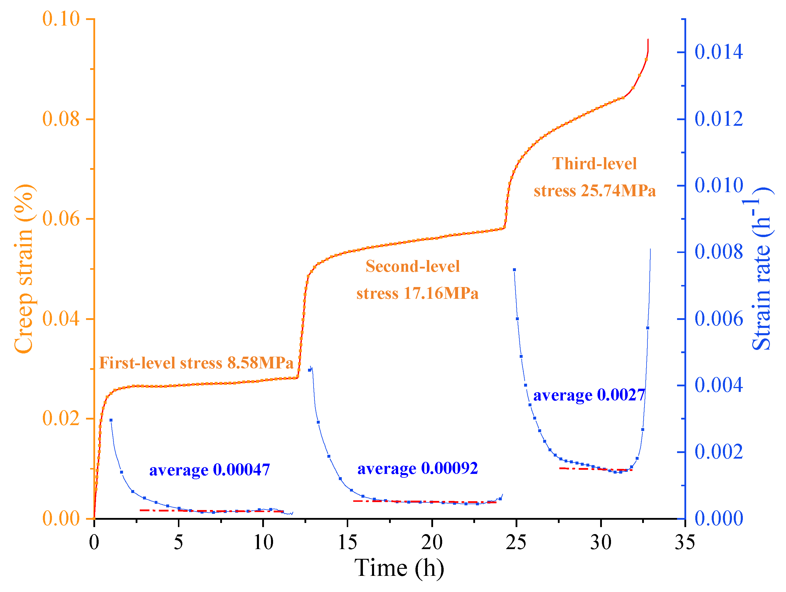
During the creep experiment, the strain–time relationship and field strain observations were recorded. The creep strain–time curve is presented in Figure 4. The experiment consisted of three creep loading stages, each displaying primary and steady-state creep phases, with accelerated creep deformation occurring during the third stage [41].
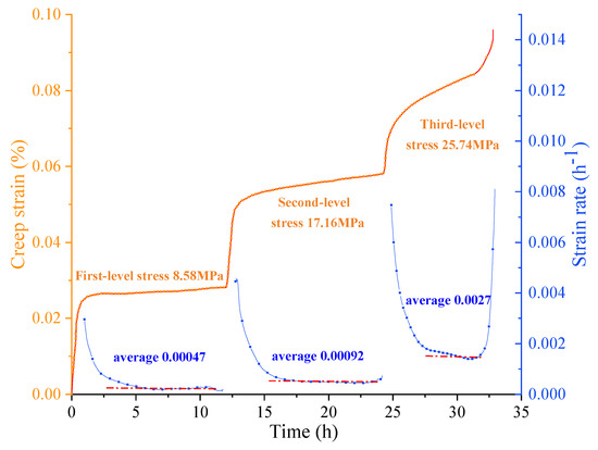
Figure 4.
The curve of creep strain vs. time and the strain rate of each loading stage.
In the first creep loading stage, as depicted in Figure 4, the sample exhibited a minimal strain increment, with a corresponding strain rate of approximately 0.00047 h−1. With increasing creep stress in the second and third loading stages, the creep strain significantly increased, reaching average strain rates of approximately 0.00092 h−1 and 0.0027 h−1, respectively. This indicates progressive damage accumulation throughout each loading stage, culminating in sample failure during the third stage.
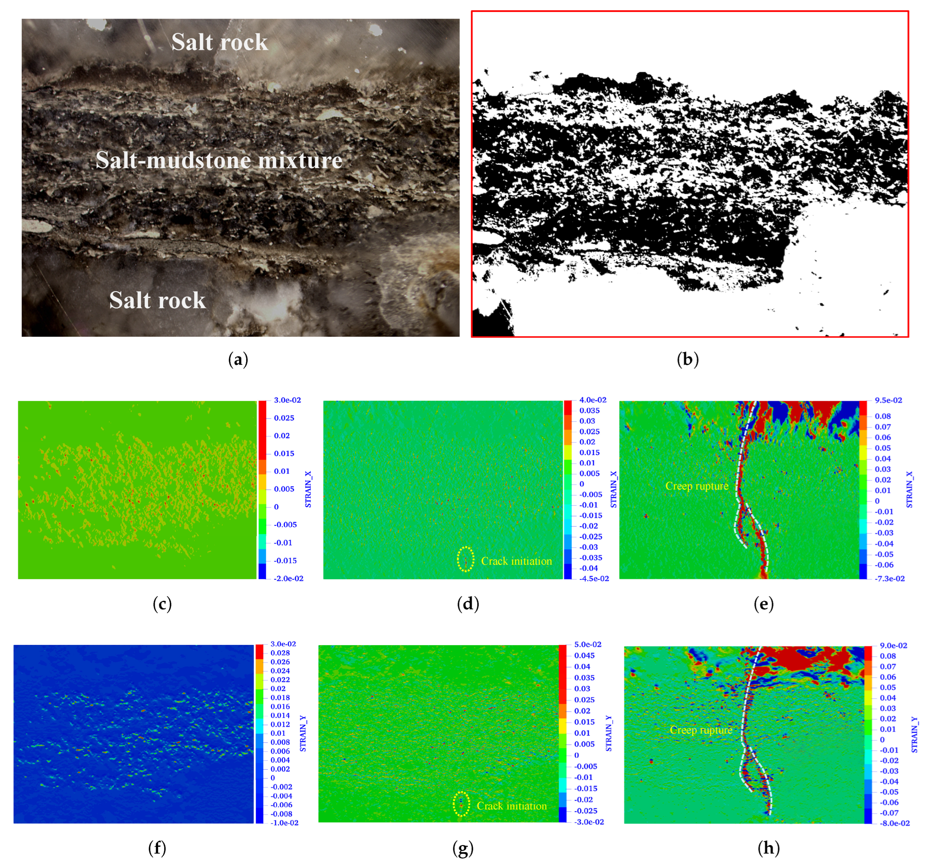
The CCD camera captured deformation in region D, as indicated in image (iv) of Figure 1. The initial intact tomography is displayed in Figure 5a. By applying a threshold-based image segmentation method, the mudstone (dark areas) and rock salt (bright areas) were extracted, as shown in Figure 5b. The segmented images suggest that salt–mudstone mixtures are predominantly distributed in the central region of the observed area.
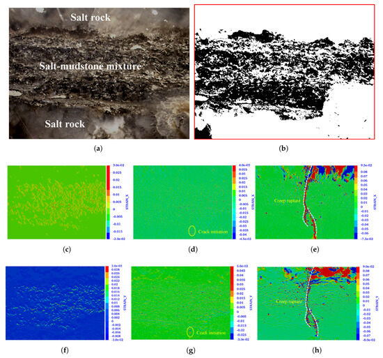
Figure 5.
Images from (a) tomography and (b) threshold segmentation of the observed area at D in part (iv) of Figure 1; the DIC contours of the (c–e) vertical and (f–h) lateral strain distribution of the first, second, and third creep loading stages, respectively.
Through digital image correlation (DIC) analysis, the vertical and lateral strain contours for the first, second, and third creep loading stages are illustrated in Figure 5c–h. As shown in Figure 5c,f, during the first creep stage, vertical and lateral strain were primarily concentrated in the middle region of the observation zone, corresponding to the bedded salt–mudstone layers. These regions exhibited compressive strain (positive values indicating compression).
As the second creep stress level was applied, as shown in Figure 5d,g, the salt–mudstone mixture remained in a compressed state, though the number of deformation sites was reduced compared to the first stage. This suggests that the salt–mudstone mixtures underwent compaction during the initial loading stage. As observed in Figure 3c, these regions contain larger pores, making them more susceptible to compaction under compression. Notably, during the second creep stage, an initial crack formed at the bottom of the observation zone within the pure rock salt.
During the third creep stage, as shown in Figure 5e,h, pronounced deformation occurred, eventually forming a fracture-like structure. Additionally, significant compressive deformation was observed in the upper rock salt region, indicating structural instability under sustained creep loading.
3.3. Evolution of Creep Damage in the Mesostructure
3.3.1. Characteristics of Damage Propagation in the Mesostructure
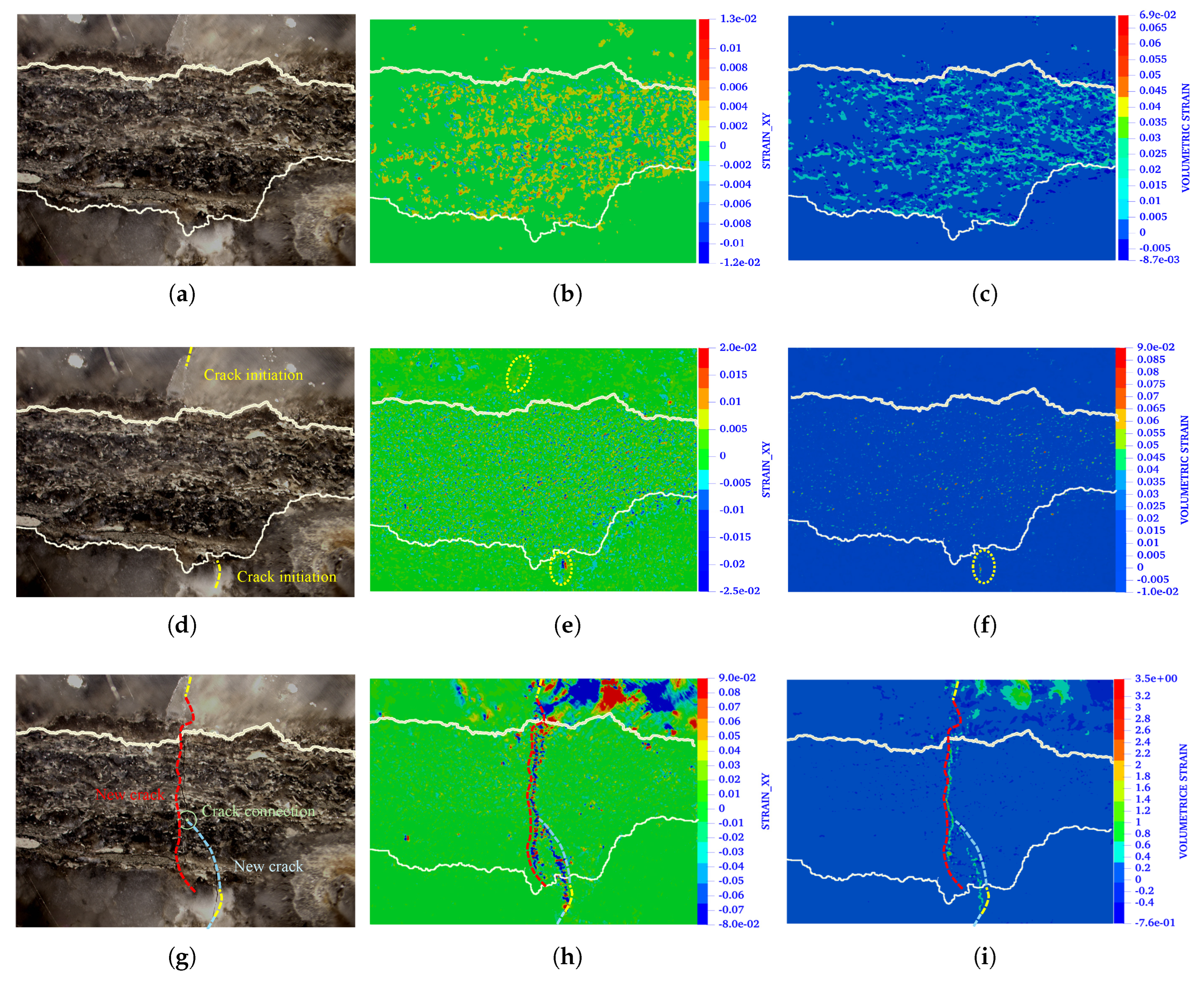
To analyze the evolution of the damage, tomographic images of a fixed zone D (as shown in image (iv) of Figure 1) during the first, second, and third creep stages are compared in Figure 6a,d,g, respectively. The variations in shear strain and volumetric strain (DIC results) within this observation zone, relative to the intact state, are presented in Figure 6b,e,h for shear strain and Figure 6c,f,i for volumetric strain. These results provide insights into the progression of damage.
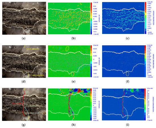
Figure 6.
Images from (a,d,g) CCD observation; (b,e,h) DIC results for shear strain and (c,f,i) volumetric strain during the first, second, and third creep loading stages, respectively.
A comparison of Figure 6a,d,g indicates that no visible cracks formed during the first creep stage. However, crack initiation occurred within the rock salt in the second stage, with subsequent propagation into the salt–mudstone mixtures.
The DIC contours of shear strain and volumetric strain reveal that during the first creep stage, as shown in Figure 6b,c, deformation was primarily controlled by the salt–mudstone interface. The distribution of shear and volumetric strains exhibits a paired pattern (positive and negative values), likely resulting from the differential stiffness between salt and mudstone grains, which induces localized deformation at their interface [42,43]. Overall, the volumetric strain suggests that the primary mechanism in the first creep stage is compaction of the mixture.
In the second creep stage, as shown in Figure 6e, a significant paired shear strain distribution emerges near the bottom boundary of the salt–mudstone mixture, while the upper region where cracking initiates exhibits minimal shear strain. The volumetric strain distribution in Figure 6f indicates that notable volumetric changes occur at the crack initiation site in the lower region, whereas the upper region experiences limited volumetric deformation. These observations suggest that crack initiation in rock salt is primarily governed by shear damage.
During the third creep stage, as illustrated in Figure 6h,i, both shear strain and volumetric strain become more pronounced along the fracture, leading to shear-induced dilatancy. The upper and lower cracks in the rock salt propagate into the salt–mudstone mixtures, eventually merging at the center of the observation zone, culminating in the failure of the tested sample.
3.3.2. Mechanism of Mesostructural Damage in Creep Deformation
As discussed in Section 3.3.1, damage originates in the pure rock salt and propagates into the salt–mudstone interlayer. To investigate the mesostructural damage mechanisms during creep deformation, the structural evolution of pure salt (point E), the interlayer (point F), and the interface (point G), as marked in image (iv) of Figure 1, is analyzed as follows.
In Figure 7, the boundaries of three salt crystals are clearly visible. During creep deformation, significant damage is observed along these boundaries, manifesting as microcracks represented by white regions in the tomography. The deformation results from crystallographic orientation-dependent plasticity under applied stress. In the primary creep stage, initial dislocation glide occurs at low densities with negligible mutual interactions, preserving the original microstructure. As creep progresses, exponential dislocation multiplication and localized clustering intensify intracrystalline slip, ultimately leading to the formation of crystallographically aligned microfractures.

Figure 7.
The evolution of damage at point E in pure rock salt (a–c) during the first, second, and third creep stages, respectively.
Additionally, severe damage is observed in the upper grain, as highlighted in the marked area, indicating transgranular fracture and crack propagation along the grain boundary.
The evolution of the salt–mudstone interface is governed by contrasts in crystallographic and mechanical properties, as summarized in Table 1. During initial loading, differential deformation arises due to the higher stiffness and lower plasticity of halite crystals compared to the more compliant mudstone matrix, resulting in interfacial stress concentrations. Prolonged stress application induces progressive particle rotation and intergranular sliding, accompanied by time-dependent microcrack nucleation at mineral boundaries. These microcracks propagate through transgranular fracture pathways and ultimately coalesce into macroscopic failure surfaces along preferential crystallographic orientations, as depicted in Figure 8 and Figure 9.
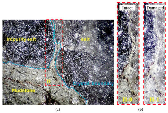
Figure 8.
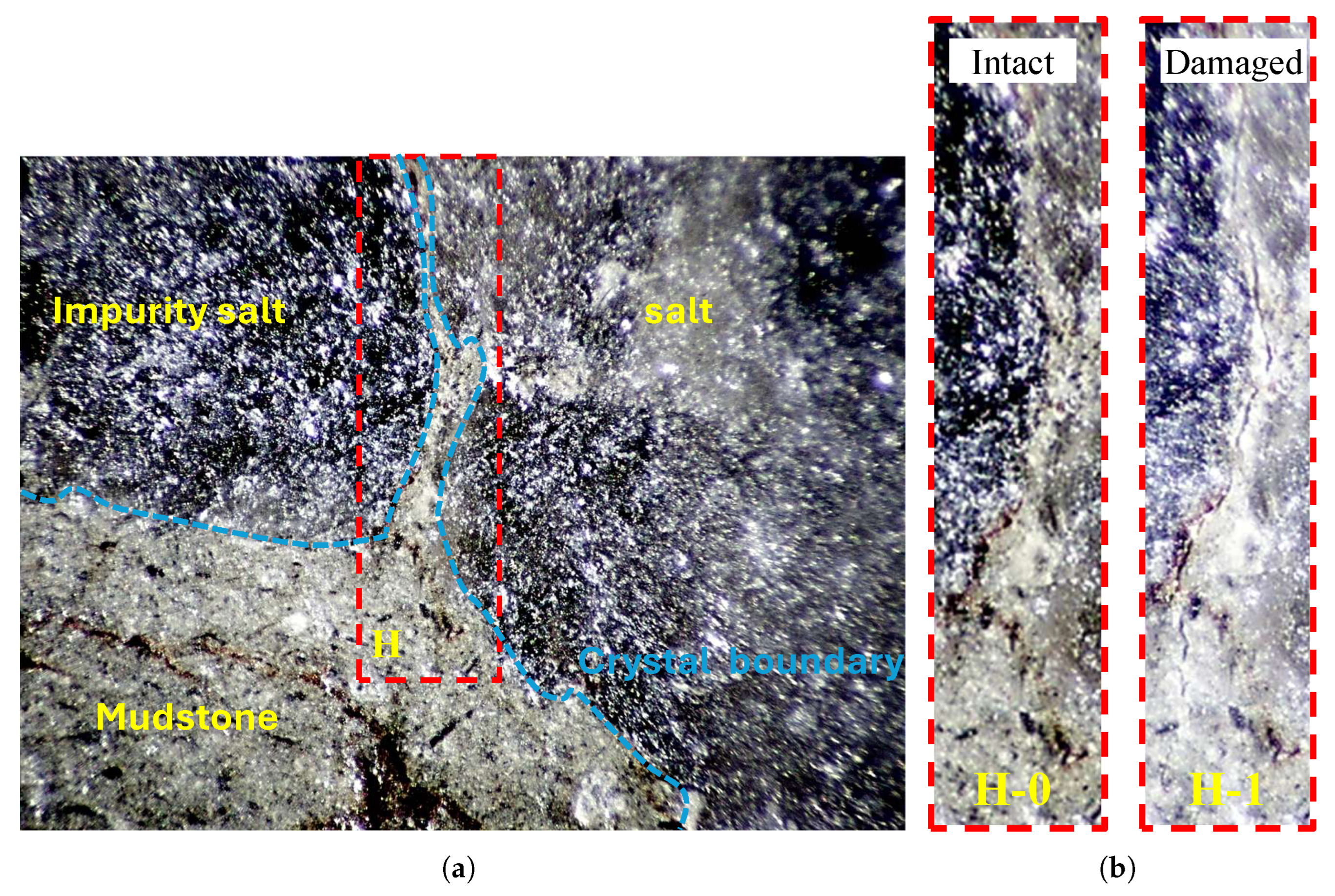
Images showing (a) tomography of the observed area of F and (b) a comparison of the interface before and after damage in the second creep stage.
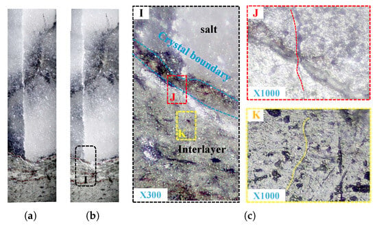
Figure 9.
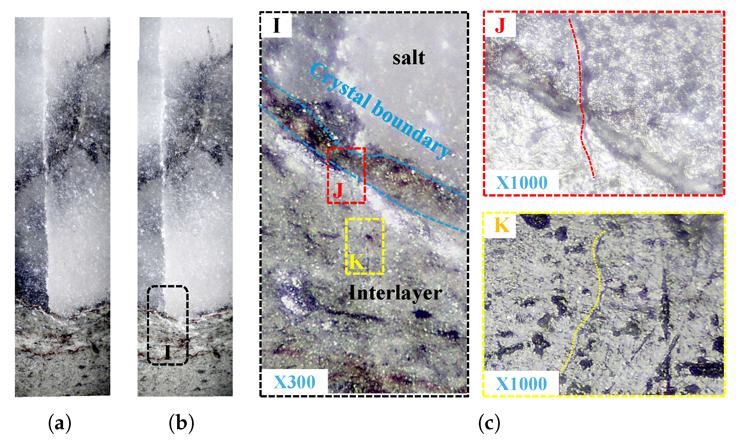
Extent of interfacial degradation in salt–mudstone interlayers of observed area G during (a) the secondary creep regime and (b) the tertiary creep regime, with (c) magnification of local features.
Within the salt–mudstone interlayer, as shown in Figure 8, damage at point H is first observed during the second creep stage. Figure 8a presents a tomography image of the observation zone, revealing a mixture of salt grains, impure salt (containing minor impurities), and mudstone. Upon reaching the second stress level, crack initiation occurs at the boundary between the impure salt and mudstone. This behavior is consistent with the SEM tomography in Figure 3c, which shows pre-existing crack-like defects at the salt–mudstone interface that promote crack initiation [44].
The interface between pure salt and the salt–mudstone interlayer at point G undergoes damage during the second and third creep stages, as illustrated in Figure 9. Figure 9a,b display tomographic images of point G during the second and third creep stages, respectively, while Figure 9c provides a magnified view of the marked region in Figure 9b.
As seen in Figure 9a, an initial crack forms within a salt grain. By the third creep stage, as shown in Figure 9b, this crack propagates into the salt–mudstone interlayer. The magnified view in Figure 9c reveals that the crack primarily propagates through the mudstone grains, which aligns with observations in Figure 8b, highlighting the relatively low mechanical strength of mudstone.
Overall, the salt–mudstone interlayer exhibits greater deformability than pure salt. Crack initiation predominantly occurs within the pure rock salt, exhibiting shear dilatancy, and subsequently propagates into the interlayer. Damage within the interlayer is primarily localized at the interfaces between salt and mudstone grains and is most pronounced in the mudstone matrix.
4. Conclusions
This study investigates the microstructural characteristics, creep deformation behavior, and mesostructural damage evolution of bedded rock salt using scanning electron microscopy (SEM) and creep testing. The key findings are as follows:
- (1)
- Bedded rock salt and mudstones exhibit significant differences in microstructure, mineral composition, and physical properties. SEM-EDS analyses reveal distinct microstructural variations among rock salt, mudstone, and their interfacial zones. As shown in Table 1, the mineral composition of bedded salt formations demonstrates greater complexity compared to the other two lithologies. Variations in grain size distribution among different mineral components result in well-developed interfacial pores with complex structures and high connectivity.
- (2)
- Microstructural heterogeneity in bedded rock salt induces incompatible creep deformation, generating additional stress fields manifested as intergranular shear damage. When superimposed stresses exceed the tensile strength of interlayers, tensile failure occurs in rock salt. During creep stages with a rate of 0.00047, mineral compaction dominates in impurity zones. As external stress increases, creep rates escalate to 0.00092 to 0.0027, triggering intergranular dislocations that initiate microcracks. These subsequently interact with pre-existing fractures, ultimately coalescing into larger discontinuities.
- (3)
- Strain nephograms demonstrate that deformation in bedded rock salt is primarily governed by salt–mudstone interfaces through shear-dominated failure mechanisms. During primary creep loading, shear strain and volumetric strain distributions reveal localized deformation concentrated in impurity zones. Secondary creep loading induces microcrack initiation at interfacial regions due to deformation incompatibility, with damage progressively propagating into adjacent rock salt. At the accelerated creep stage, dilatancy damage intensifies predominantly in upper strata, where interconnected microcracks in impurity zones coalesce with newly formed fractures.
This study primarily investigates the microstructural evolution of layered rock salt under different stress levels, emphasizing the creep deformation and damage propagation mechanisms at the microscale; while we recognize the significant impact of temperature and impurity content on the mechanical behavior of rock salt, these factors are beyond the scope of the current work. Future research will extend our analysis to incorporate the effects of temperature and compositional variations, enabling a more comprehensive understanding of the long-term stability of bedded salt formations.
Author Contributions
Conceptualization, H.Y.; methodology, H.Y. and F.R.; software, T.Z.; investigation, F.R.; resources, H.Y.; data curation, Z.C. and H.Z.; writing—original draft preparation, F.R.; visualization, Z.L. and H.Z.; supervision, H.Y.; project administration, H.Y.; funding acquisition, H.Y. All authors have read and agreed to the published version of the manuscript.
Funding
This research was funded by the Natural Science Funding Committee of Hebei Province (Grant No. E2024508032) and the Fundamental Research Funds for the Central Universities (Grant No. 3142023056).
Institutional Review Board Statement
Not applicable.
Informed Consent Statement
Not applicable.
Data Availability Statement
All available data are included in the present paper.
Acknowledgments
Thanks are given to Zhide Wu and BingBing Liu for their extensive help with the experiment and test materials.
Conflicts of Interest
The authors declare no conflicts of interest.
References
- Song, Y.; Song, R.; Liu, J. Hydrogen tightness evaluation in bedded salt rock cavern: A case study of Jintan, China. Int. J. Hydrogen Energy 2024, 48, 30489–30506. [Google Scholar] [CrossRef]
- Liu, W.; Jiang, D.; Chen, J.; Daemen, J.J.K.; Tang, K. Comprehensive feasibility study of two-well-horizontal caverns for natural gas storage in thinly-bedded salt rocks in China. Energy 2018, 143, 1006–1019. [Google Scholar] [CrossRef]
- Zhang, X.; Liu, W.; Jiang, D.; Qiao, W.; Liu, E.; Zhang, N. Investigation on the influences of interlayer contents on stability and usability of energy storage caverns in bedded rock salt. Energy 2021, 231, 120968. [Google Scholar] [CrossRef]
- Wang, T.; Liao, Y.; Yang, C.; Xie, D.; Chen, W.; Wang, D. Gas transport model in pore heterogeneous bedded salt rock: Implications for tightness evaluation of salt cavern gas storage. Gas Sci. Eng. 2024, 121, 205185. [Google Scholar] [CrossRef]
- Zhang, N.; Liu, W.; Zhang, Y.; Shan, P.; Shi, X. Microscopic pore structure of surrounding rock for underground strategic petroleum reserve (SPR) caverns in bedded rock salt. Energies 2020, 13, 1565. [Google Scholar] [CrossRef]
- Liu, W.; Li, Y.; Yang, C.; Daemen, J.J.; Yang, Y.; Zhang, G. Permeability characteristics of mudstone cap rock and interlayers in bedded salt formations and tightness assessment for underground gas storage caverns. Eng. Geol. 2015, 193, 212–223. [Google Scholar] [CrossRef]
- Houben, M.E.; Barnhoorn, A.; Lie-A-Fat, J.; Ravestein, T.; Peach, C.J.; Drury, M.R. Microstructural characteristics of the Whitby Mudstone formation (UK). Mar. Pet. Geol. 2016, 70, 185–200. [Google Scholar] [CrossRef]
- Thiemeyer, N.; Habersetzer, J.; Peinl, M.; Zulauf, G.; Hammer, J. The application of high resolution X-ray computed tomography on naturally deformed rock salt: Multi-scale investigations of the structural inventory. J. Struct. Geol. 2015, 77, 92–106. [Google Scholar] [CrossRef]
- Teles, A.P.; Machado, A.C.; Pepin, A.; Bize-Forest, N.; Lopes, R.T.; Lima, I. Analysis of subterranean Pre-salt carbonate reservoir by X-ray computed microtomography. J. Pet. Sci. Eng. 2016, 144, 113–120. [Google Scholar] [CrossRef]
- Pavón, E.; Alba, M.D. Swelling layered minerals applications: A solid state NMR overview. Prog. Nucl. Magn. Reson. Spectrosc. 2021, 124, 99–128. [Google Scholar]
- Liang, K.; Xie, L.; He, B.; Zhao, P.; Zhang, Y.; Hu, W. Effects of grain size distributions on the macro-mechanical behavior of rock salt using micro-based multiscale methods. Int. J. Rock Mech. Min. Sci. 2021, 138, 104592. [Google Scholar] [CrossRef]
- Vandeginste, V.; Ji, Y.; Buysschaert, F.; Anoyatis, G. Mineralogy, microstructures and geomechanics of rock salt for underground gas storage. Deep. Undergr. Sci. Eng. 2023, 2, 129–147. [Google Scholar] [CrossRef]
- Liu, Z.; Ma, C.; Wei, X.A. Electron scanning characteristics of rock materials under different loading methods: A review. Geomech. Geophys. Geo-Energy Geo-Resour. 2022, 8, 80. [Google Scholar] [CrossRef]
- Desbois, G.; Urai, J.L.; Kukla, P.A. Morphology of the pore space in claystones–evidence from BIB/FIB ion beam sectioning and cryo-SEM observations. eEarth Discuss. 2009, 4, 1–19. [Google Scholar] [CrossRef]
- Schléder, Z.; Urai, J.L. Microstructural evolution of deformation-modified primary halite from the Middle Triassic Röt Formation at Hengelo, The Netherlands. Int. J. Earth Sci. 2005, 94, 941–955. [Google Scholar] [CrossRef]
- Adamuszek, M.; Tămaș, D.M.; Barabasch, J.; Urai, J.L. Rheological stratification in impure rocksalt during long-term creep: Morphology, microstructure and numerical models of multilayer folds in the Ocnele Mari salt mine, Romania. Solid Earth Discuss. 2021, 2021, 1–40. [Google Scholar]
- Martin-Clave, C.; Ougier-Simonin, A.; Vandeginste, V. Impact of second phase content on rock salt rheological behavior under cyclic mechanical conditions. Rock Mech. Rock Eng. 2021, 54, 1–23. [Google Scholar] [CrossRef]
- He, J.; Li, Y.; Jin, Y.; Wang, A.; Zhang, Y.; Jia, J.; Liang, D. Study on mechanical problems of complex rock mass by composite material micromechanics methods: A literature review. Front. Earth Sci. 2022, 9, 808161. [Google Scholar] [CrossRef]
- Cheng, Y.; Song, Z.; Liu, Z.; Tian, X.; Qian, W.; Lu, X.; Yang, T. Micro-cracking morphology and dynamic fracturing mechanism of natural brittle sandstone containing layer structure under compression. Constr. Build. Mater. 2024, 425, 136051. [Google Scholar] [CrossRef]
- Gelencsér, O.; Szakács, A.; Gál, Á.; Szabó, Á.; Dankházi, Z.; Tóth, T.; Falus, G. Microstructural study of the Praid Salt Diapir (Transylvanian basin, Romania) and its implication on deformation history and hydrogen storage potential. Acta Geod. Geophys. 2024, 59, 343–365. [Google Scholar] [CrossRef]
- Zheng, Z.; Wang, G.; Hu, X.; Niu, C.; Ma, H.; Liao, Y.; Zhao, K.; Zeng, Z.; Li, H.; Yang, C. Microstructural evolution and mechanical behaviors of rock salt in energy storage: A molecular dynamics approach. Int. J. Rock Mech. Min. Sci. 2024, 182, 105882. [Google Scholar] [CrossRef]
- Mansouri, H.; Ajalloeian, R. Mechanical behavior of salt rock under uniaxial compression and creep tests. Int. J. Rock Mech. Min. Sci. 2018, 110, 19–27. [Google Scholar] [CrossRef]
- Khan, T.H.; Myers, M.T.; Hathon, L.; Unomah, G.C. Time-Scaling Creep in Salt Rocks for Underground Storage. Petrophysics- SPWLA J. Form. Eval. Reserv. Descr. 2023, 64, 954–969. [Google Scholar] [CrossRef]
- Gao, R.; Wu, F.; Chen, J.; Zhu, C.; Ji, C. Study on creep characteristics and constitutive model of typical argillaceous salt rock in energy storage caverns in China. J. Energy Storage 2022, 50, 104248. [Google Scholar] [CrossRef]
- Fourmeau, M.; Liu, W.; Li, Z.; Nelias, D.; Fan, J.; Tian, H. Research status of creep–fatigue characteristics of salt rocks and stability of compressed air storage in salt caverns. Earth Energy Sci. 2024, 1, 98–116. [Google Scholar] [CrossRef]
- Lyu, C.; Liu, J.; Ren, Y.; Liang, C.; Zhang, Q. Study on long-term uniaxial compression creep mechanical behavior of rocksalt-mudstone combined body. Int. J. Damage Mech. 2022, 31, 27. [Google Scholar] [CrossRef]
- Zhao, Y.; Wang, X.; Tang, W.; Li, Y.; Lin, H.; Wang, Y.; Zhang, L. Creep behavior of layered salt rock under triaxial loading and unloading cycles. Appl. Rheol. 2023, 33, 20230103. [Google Scholar]
- Richards, L.; King, R.C.; Collins, A.S.; Sayab, M.; Khan, M.A.; Haneef, M.; Morley, C.K.; Warren, J. Macrostructures vs. microstructures in evaporite detachments: An example from the Salt Range. Pak. J. Asian Earth Sci. 2015, 113, 922–934. [Google Scholar]
- Zelin, Z.; Wang, T. On creep behavior of mudstone in the Tianshui area, China. Bull. Eng. Geol. Environ. 2022, 81, 321. [Google Scholar] [CrossRef]
- Tackie-Otoo, B.N.; Haq, M.B. A comprehensive review on geo-storage of H2 in salt caverns: Prospect and research advances. Fuel 2024, 356, 129609. [Google Scholar] [CrossRef]
- Grgic, D.; Al Sahyouni, F.; Golfier, F.; Moumni, M.; Schoumacker, L. Evolution of gas permeability of rock salt under different loading conditions and implications on the underground hydrogen storage in salt caverns. Rock Mech. Rock Eng. 2022, 55, 691–714. [Google Scholar] [CrossRef]
- Yang, C.; Wang, T.; Li, Y.; Yang, H.; Li, J.; Qu, D.A.; Daemen, J.J.K. Feasibility analysis of using abandoned salt caverns for large-scale underground energy storage in China. Applied Energy 2015, 137, 467–481. [Google Scholar]
- Zhang, Q.; Liu, J.; Wang, L.; Luo, M.; Liu, H.; Xu, H.; Zou, H. Impurity effects on the mechanical properties and permeability characteristics of salt rock. Energies 2020, 13, 1366. [Google Scholar] [CrossRef]
- Meng, T.; Jianliang, P.; Feng, G.; Hu, Y.; Zhang, Z.; Zhang, D. Permeability and porosity in damaged salt interlayers under coupled THMC conditions. J. Pet. Sci. Eng. 2022, 211, 110218. [Google Scholar]
- Stormont, J.C. In situ gas permeability measurements to delineate damage in rock salt. Int. J. Rock Mech. Min. Sci. 1997, 34, 1055–1064. [Google Scholar] [CrossRef]
- Li, Y.; Liu, W.; Yang, C.; Daemen, J.J. Experimental investigation of mechanical behavior of bedded rock salt containing inclined interlayer. Int. J. Rock Mech. Min. Sci. 2014, 69, 39–49. [Google Scholar]
- Wang, W.; Liao, H.; Huang, Y. Rock fracture tracing based on image processing and SVM. In Proceedings of the Third International Conference on Natural Computation (ICNC), Haikou, China, 24–27 August 2007; pp. 632–635. [Google Scholar]
- Pramanik, S.K.; Ganguly, B. Crystal habit modification of sodium chloride using habit modifiers: A dive into more than 50 years of research and development on crystal habit modification of rock-salt crystals. CrystEngComm 2025. [Google Scholar] [CrossRef]
- Eyankware, M.O.; Ogwah, C.; Ike, J.C. A synoptic review of mineralogical and chemical characteristics of clays in the southern part of Nigeria. Res. Ecol. 2021, 3, 32–45. [Google Scholar] [CrossRef]
- Rowan, M.G.; Urai, J.L.; Fiduk, J.C.; Kukla, P.A. Deformation of intrasalt competent layers in different modes of salt tectonics. Solid Earth 2019, 10, 987–1013. [Google Scholar]
- Zhou, X.; Pan, X.; Berto, F. A state-of-the-art review on creep damage mechanics of rocks. Fatigue Fract. Eng. Mater. Struct. 2022, 45, 627–652. [Google Scholar] [CrossRef]
- Swift, G.M.; Reddish, D.J. Underground excavations in rock salt. Geotech. Geol. Eng. 2005, 23, 17–42. [Google Scholar] [CrossRef]
- Dong, Z.; Li, Y.; Li, H.; Shi, X.; Ma, H.; Zhao, K.; Zhao, A. Influence of loading history on creep behavior of rock salt. J. Energy Storage 2022, 55, 105434. [Google Scholar] [CrossRef]
- Kuzmin, V.A.; Skibitskaya, N.A. Use of scanning electron microscopy for the classification of rocks of oil and gas reservoirs. J. Surf. Investig. X-ray Synchrotron Neutron Tech. 2017, 11, 160–166. [Google Scholar] [CrossRef]
Disclaimer/Publisher’s Note: The statements, opinions and data contained in all publications are solely those of the individual author(s) and contributor(s) and not of MDPI and/or the editor(s). MDPI and/or the editor(s) disclaim responsibility for any injury to people or property resulting from any ideas, methods, instructions or products referred to in the content. |
© 2025 by the authors. Licensee MDPI, Basel, Switzerland. This article is an open access article distributed under the terms and conditions of the Creative Commons Attribution (CC BY) license (https://creativecommons.org/licenses/by/4.0/).

