Article

Study on AC Loss of REBCO Tape Encapsulated with Magnetic Materials

1
School of Intelligent Manufacturing and Electronic Engineering, Wenzhou University of Technology, Wenzhou 325035, China
2
School of Data Science and Artificial Intelligence, Wenzhou University of Technology, Wenzhou 325035, China
3
Key Laboratory of Magnetic Suspension Technology and Maglev Vehicle (Ministry of Education), Southwest Jiaotong University, Chengdu 610031, China
4
Southwestern Institute of Physics, Chengdu 610041, China
*
Authors to whom correspondence should be addressed.
Crystals 2025, 15(5), 407; https://doi.org/10.3390/cryst15050407 (registering DOI)
Submission received: 17 March 2025 / Revised: 22 April 2025 / Accepted: 22 April 2025 / Published: 26 April 2025
(This article belongs to the Special Issue Superconductors and Magnetic Materials)

Abstract

:
REBCO coated conductors have a multi-layer structure, and the outer encapsulation layer is generally made of non-magnetic copper material. This paper proposes a new structure of REBCO tape, which replaces the copper layer with magnetic material to explore its transport loss and magnetization loss. The results indicate that copper-encapsulated REBCO tapes have lower transport losses at low currents, while tapes encapsulated with strong magnetic nickel alloy materials have the highest transport losses. At high transport currents, the transport losses of REBCO tapes encapsulated with different materials are almost equal. At low fields, the magnetization loss of the tape encapsulated with strong magnetic nickel alloy is lower, while the magnetization loss of the tape encapsulated with copper is the highest, due to the magnetic shielding effect of the magnetic material. Under high-field conditions, the difference in magnetization loss between magnetic material-encapsulated tapes and copper-encapsulated tapes decreases.

1. Introduction

REBCO coated conductors exhibit high critical current density and thermal stability under external-field conditions, making them widely applicable in fields such as power system and high-field magnets [1,2,3]. When superconducting tapes operate in alternating current or alternating external fields, AC losses may occur. Excessive AC losses may cause the tapes to quench, thereby affecting the stability of the system [4,5,6,7,8]. Therefore, how to reduce the AC loss of superconducting tapes has always been a topic of interest in this field.
As a result of the anisotropic characteristics of REBCO tapes, the AC losses caused by alternating magnetic fields of the same amplitude parallel to the wide face of the tape are much smaller than those caused by a magnetic field perpendicular to the wide face of the tape [9]. Therefore, if the magnetic field perpendicular to the wide face of the tape can be reduced, the AC loss of the tape can be reduced. It is regarded that arranging magnetic materials around superconductors is an efficient way to decrease the AC losses of superconductors. This is because magnetic materials are capable of changing magnetic field distribution, thereby lessening the magnetic field perpendicular to the tape’s surface. Therefore, some research groups have reported the addition of magnetic materials to reduce AC losses in high-temperature superconducting tapes, cables, and magnets [10,11,12,13,14,15,16,17]. Liu et al. reported the difference in AC losses between coils wound with and without magnetic substrate tape, and found that coils wound with magnetic substrate tape had higher transport losses [18]. Chen et al. reported that for stacked REBCO cables, winding magnetic materials around the stacked tapes can reduce the magnetization loss of the cable [19]. Jiang’s research group reported that magnetic flux diverters can effectively reduce the transport loss of REBCO coils [20,21]. Zhang et al. reviewed the application of magnetic materials in superconducting electrical machines to reduce coil AC losses [22]. However, most of the above reports introduced magnetic materials around commercial REBCO tapes to reduce AC losses in tapes, cables, or coils. This study investigates the AC losses of commercially available REBCO tapes by trying to change the structure of the tape, replacing the traditional copper encapsulation layer with a magnetic encapsulation layer, in both self and external fields.
This study involved comparing the transport loss and magnetization loss of REBCO tapes that were encapsulated using three different materials, which were copper, a nickel alloy with weak magnetic properties, and a nickel alloy with strong magnetic properties. The peak of the transport current ranges from 0.1 Ic0 to 0.9 Ic0, and the peak of the external magnetic field ranges from 0.01 T to 0.15 T. The total loss, loss components, and loss generation mechanism of the tape will be discussed.

2. Geometric Models and Numerical Method

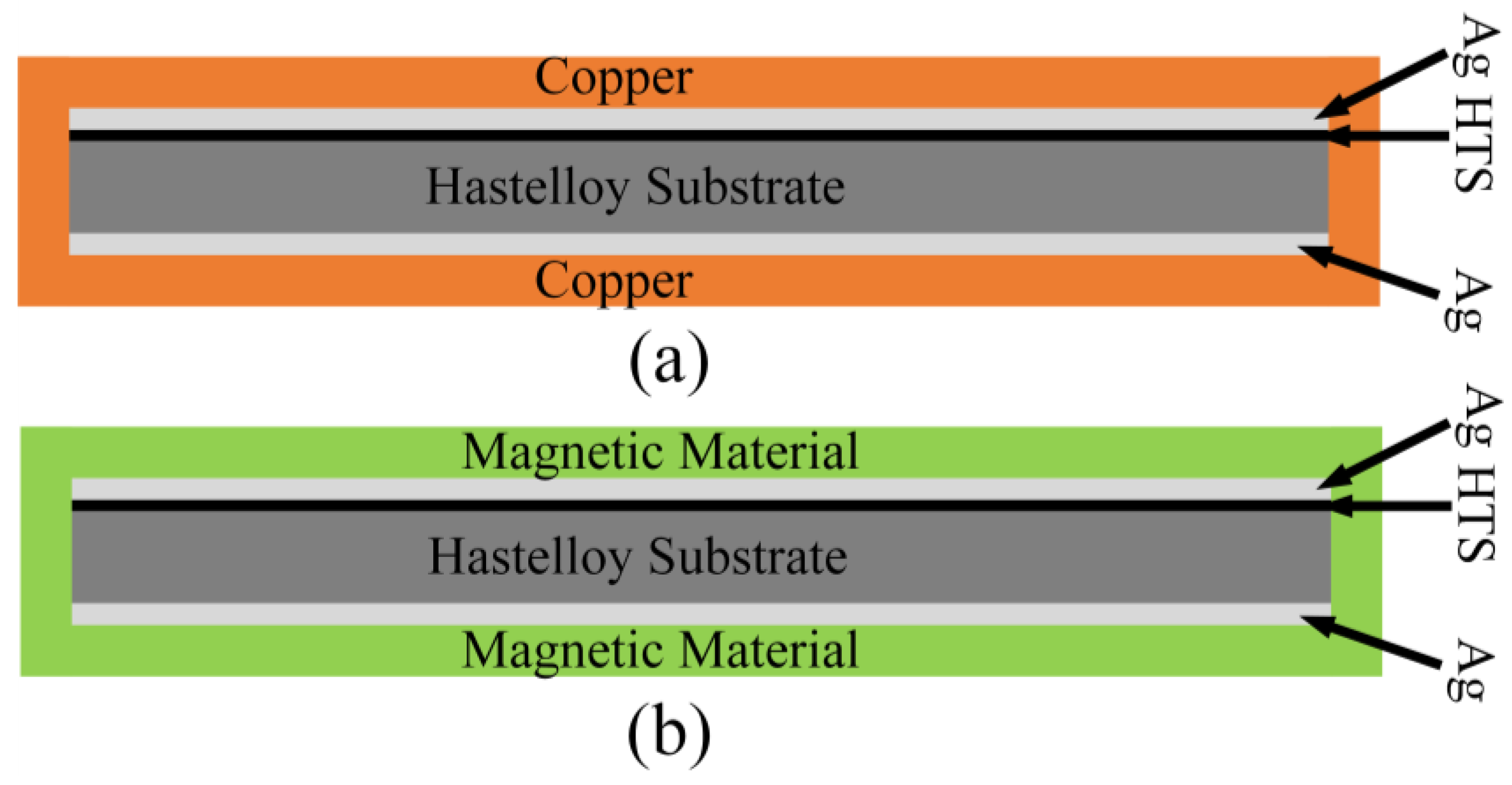
2.1. Geometric Models of REBCO Tapes Encapsulated with Different Materials

Figure 1 shows the cross-sectional schematic diagram of REBCO tapes encapsulated with various materials. Figure 1a shows the tapes encapsulated with copper, consistent with Superpower SCS4050 structure. Figure 1b shows the tapes encapsulated with magnetic materials. The two types of tapes have the same material for each layer except for the encapsulation layer, and the geometric dimensions are also the same. The width of the silver layer, superconducting layer, and Hastelloy substrate layer is 4 mm, and their respective thicknesses are 2 μm for the silver layer, 1 μm for the superconducting layer, and 50 μm for the Hastelloy substrate layer. The width of the encapsulation layer is 4.04 mm, and the thickness is 20 μm. The magnetic materials used for the encapsulation layer include one type of weakly magnetic nickel alloy and another type of strongly magnetic nickel alloy.

2.2. Numerical Method

The AC loss calculation and electromagnetic characteristics analysis of REBCO tape are based on solving the H-formulation [23,24,25], as shown in Equation (1) below:
( μ 0 μ r H ) t + × ρ × H = 0
where μ0 is the magnetic permeability in vacuum, with a value of 4π × 10−7 H/m, μr is the relative magnetic permeability of the material, and for magnetic materials, μr is a function of the magnetic field strength H. The relative magnetic permeabilities of the nickel alloy with weak magnetism and the nickel alloy with strong magnetism are given in Equations (2) and (3) [9,25], and for non-magnetic materials, μr = 1. ρ is the resistivity of the material, as shown in Table 1. The resistivity of the superconducting layer is ρ = E c J c ( B ) J J c B n 1 , Ec is the critical electric field criterion, and n is the power exponent of the nonlinear resistance of the superconductor, as shown in Table 1. Jc (B) is the critical current density of the tape as a function of the magnetic field, as shown in Equation (4) [26,27]:
μ r ( H ) = 1 + 30,600 ( 1 e x p ( ( H / 295 ) 2.5 ) ) H 0.81 + 45 e x p ( ( H / 120 ) 2.5 )
μ r H = 1 + 1,200,000 ( 1 e x p ( ( H / 70 ) 3.2 ) ) H 0.99
J c B = J c 0 1 + k 2 B 2 + B 2 / B 0 α
where Jc0 represents the critical current density of the superconducting layer in zero-field condition, while B and B// stand for the vertical and parallel components, respectively, of the magnetic field on the face of tape, and k, B0 and α are material-related parameters, as shown in Table 1.
The transport current is applied by integrating the current density across the cross-section of the tape, as shown in Equation (5) below:
I t t = I p sin 2 π f t = Ω J d Ω
where Ip is the peak value of the transport current, and the frequency varies from 50 Hz to 1000 Hz.
The external magnetic field is achieved by applying Dirichlet boundary conditions to the air domain boundary around the tape, as shown in Equation (6):
B e x t t = B p sin ( 2 π f t )
where Bp is the peak value of the external magnetic field, and the frequency varies from 50 Hz to 1000 Hz.

2.3. AC Loss Calculation

The calculation of AC loss per unit length per cycle of REBCO tape is shown in Equation (7) [26]:
Q i = 2 T / 2 T d t Ω i E · J d Ω d t
where the period is denoted as T, and Ωi refers to the domain of interest within the tape. In the case of superconductors, Qi indicates hysteresis loss, whereas for conventional metals, Qi stands for eddy current loss.
Ferromagnetic materials have not only eddy current losses but also hysteresis loss. The formula for calculating hysteresis loss is presented in Equation (8) [26]:
Q f e = Ω s q f e d Ω
where Ωs denotes the cross-sectional area of the magnetic encapsulation layer. As for weakly magnetic materials [26], the following apply:
q f e B m a x = 4611.4 B m a x 1.884                                                                                                     B m a x     0.164   T 210 1 exp 6.5 B m a x 4                                                 B m a x > 0.164   T
and for strong magnetic materials [14], the following apply:
q f e B m a x = 171.2 B m a x 1.344                                                                                                     0.1   T B m a x     1.53   T 375 1 exp B m a x 1.407 6.787                                                                 B m a x > 1.53   T
where Bmax is the maximum magnetic induction intensity in an ac cycle. Therefore, the total loss of the tape is shown in Equation (11):
Q t o t a l = Q s c + Q m e t + Q f e
where Qsc is the hysteresis loss of the superconducting layer, Qmet is the eddy current loss of the metal layer, and Qfe is the hysteresis loss of the magnetic material.

3. Result and Discussion
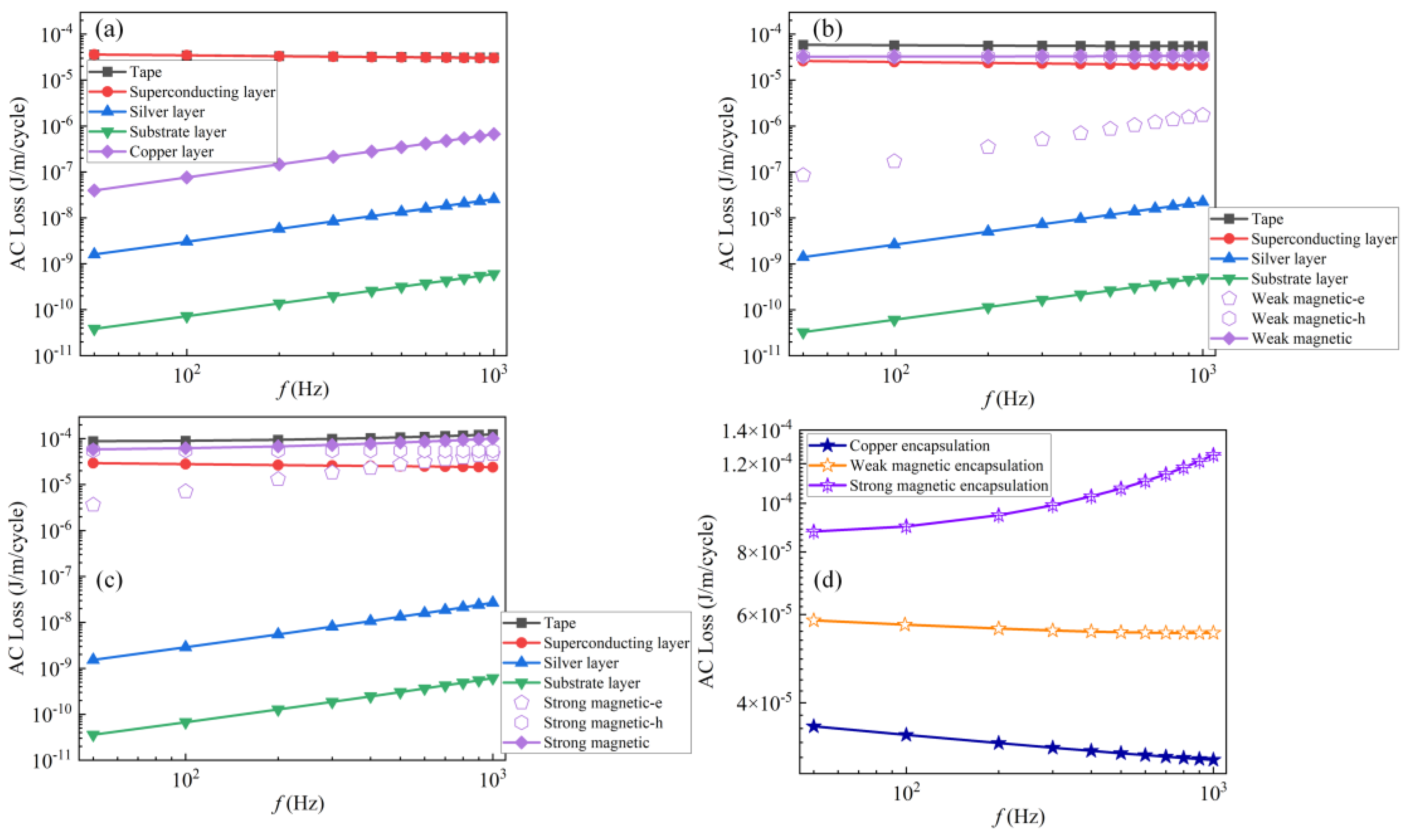
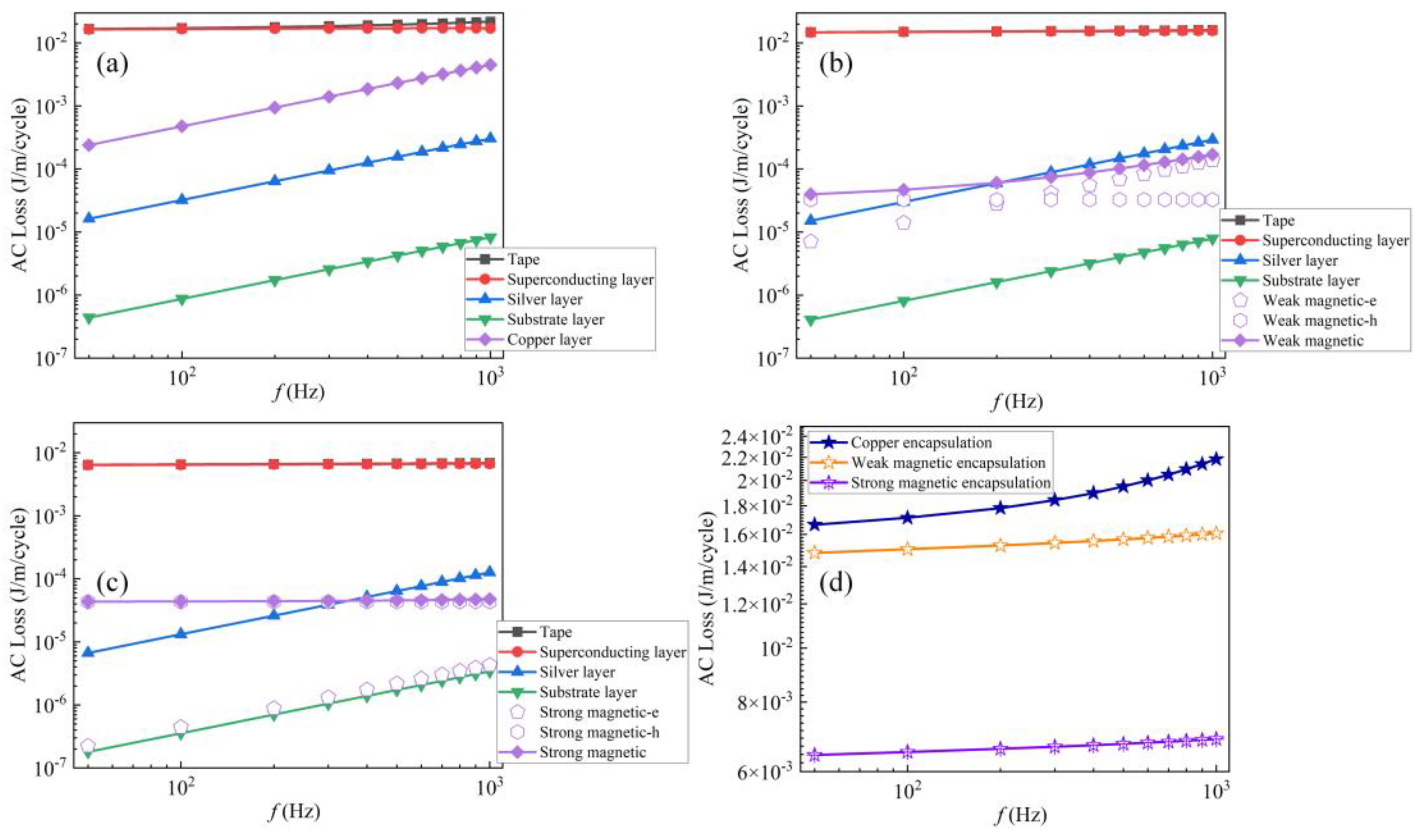
3.1. Transport Loss

Figure 2 shows the variation in transport loss of REBCO tapes encapsulated with different materials under different-amplitude transport currents, f = 50 Hz. In the legend, the tape, superconducting layer, silver layer, substrate layer, copper layer, weak magnetic and strong magnetic represent the total loss of the tape, superconducting layer loss, silver layer loss, substrate layer loss, copper layer loss, weak magnetic encapsulation layer loss and strong magnetic encapsulation layer loss, respectively. Figure 2a shows the transport loss of each part of the commercial copper-encapsulated REBCO tape as a function of the transport current. As the transport current rises, the transport loss shows a gradual upward trend. Moreover, the total loss of the superconducting tape is nearly entirely attributed to the hysteresis loss within the superconducting layer. The calculated transport loss value matches the loss value obtained from the Norris model [28], which is an analytical result of transport loss derived from the critical state model when Jc is a constant. Figure 2b illustrates how the transport losses of different parts of the REBCO tape encapsulated by the weak magnetic nickel alloy change with the transport current. At lower transport current, the overall loss of REBCO tapes is almost fully contributed by the iron loss of the encapsulation layer. At this time, the hysteresis loss of the superconducting layer is much smaller than that of the copper-encapsulated tapes. For example, when Ip/Ic0 = 0.1, the hysteresis loss of the high-temperature superconducting layer in weakly magnetic material-encapsulated tapes is five orders of magnitude smaller than that of copper-encapsulated tapes. This may be due to the magnetic material increasing the critical current of the tape under the self-field [29]. At higher transport currents, the total loss of the tape mainly comes from the hysteresis loss of the superconducting layer. The variation in losses in different parts of the REBCO tape encapsulated with strong magnetic nickel alloy with respect to the transport current is depicted in Figure 2c. It exhibits a similar transport loss variation law with current as the tape encapsulated with weak magnetic nickel alloy. In addition, the hysteresis loss of the superconducting layer at low transport currents is lower compared to the tapes encapsulated with the first two materials. The difference in total loss between REBCO tapes encapsulated with three different materials is shown in Figure 2d. It can be seen that under low transport current, the total loss of the strongly magnetic nickel alloy-encapsulated tape is the highest, while the copper-encapsulated tape has the smallest transport loss. As the transport current increases, the difference between the three becomes increasingly smaller. When Ip/Ic0 = 0.9, the transport losses of the three are approximately equal.
In order to analyze why the hysteresis losses of the superconducting layers in the REBCO tape encapsulated with three materials differ greatly at low transport currents and show small differences at high transport currents, the current density J/Jc distribution of the superconducting layers at low and high transport currents is plotted in Figure 3. When the transport current Ip/Ic0 is 0.1 and t = 3/4 cycle, that is, the moment when the alternating transport current reaches its peak, the current density J/Jc of the superconducting layer of the copper-encapsulated tape is the highest, followed by the weak magnetic material-encapsulated tape, and that of the strong magnetic material-encapsulated tape is the smallest, as shown by the green dashed box in Figure 3. Consequently, among all the tapes, the copper-encapsulated tape has the highest hysteresis loss in its superconducting layer, while the tape encapsulated with strong magnetic material has the lowest. When the transport current Ip/Ic0 is 0.9 and t = 3/4 cycle, the difference in current density distribution of the superconducting layer of the tapes encapsulated with the three materials is small; specifically, the maximum J/Jc value shown in the green dashed box in the figure is almost identical. So, at this stage, the REBCO tapes encapsulated by the three materials have nearly identical hysteresis losses in their superconducting layers.
Figure 4 shows the frequency-dependent transport loss of REBCO tapes encapsulated with different materials when the transport current is Ip/Ic0 = 0.4. Figure 4a shows the frequency-dependent transport loss of copper-encapsulated tapes. As the frequency increases, the eddy current loss of the metal layer increases proportionally to the applied frequency, while the hysteresis loss of the superconducting layer slightly decreases with increasing frequency, which is consistent with previous reported results [26,27]. At this point, the total loss of the tape mainly comes from the hysteresis loss of the high-temperature superconducting layer; therefore, the total loss of the tape slightly decreases with increasing frequency. Figure 4b shows the variation in transport loss of weakly magnetic nickel alloy-encapsulated tape with frequency. As the frequency increases, the eddy current loss of the metal layer gradually increases, and the hysteresis loss of the superconducting layer slightly decreases, while the hysteresis loss in the weakly magnetic nickel alloy remains almost unchanged. At this point, the total loss of the tape mainly comes from the hysteresis loss of the superconducting layer, and the hysteresis loss of the weakly magnetic nickel alloy, that is, the total loss, slightly decreases with increasing frequency. Figure 4c shows the frequency-dependent transport loss of the tape encapsulated with strong magnetic nickel alloy. As the frequency increases, the change rule of transport loss in each layer is similar to that of the weak magnetic nickel alloy-encapsulated tape. However, due to the contribution of eddy current loss in the magnetic encapsulation layer to the total loss, the total loss of the tape gradually increases with the increase in frequency. Figure 4d shows the total transport loss of tapes encapsulated with three different materials as a function of frequency. Within the frequency range studied, copper-encapsulated tapes have the lowest transport loss, while strongly magnetic nickel alloy-encapsulated tapes have the highest transport loss.

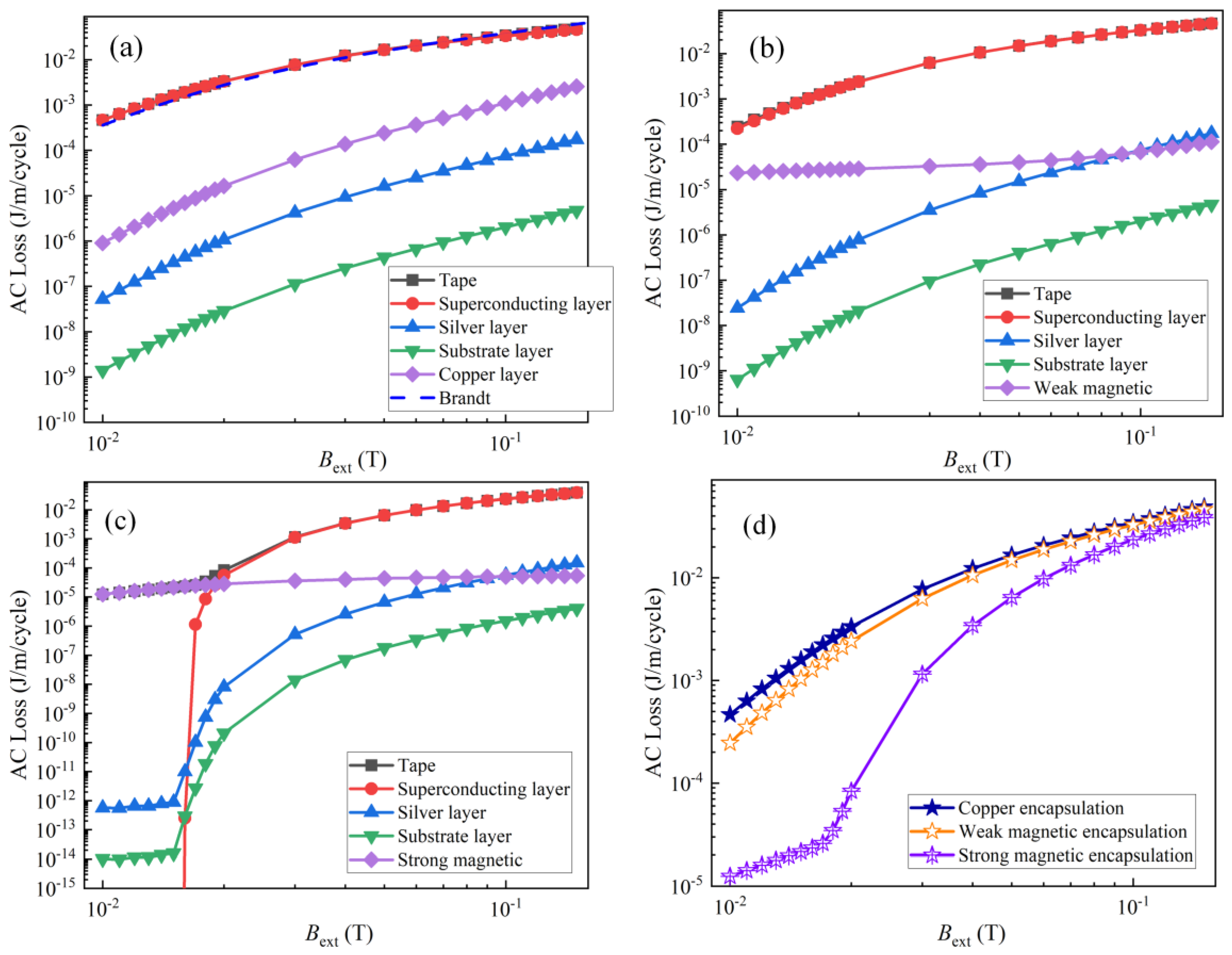
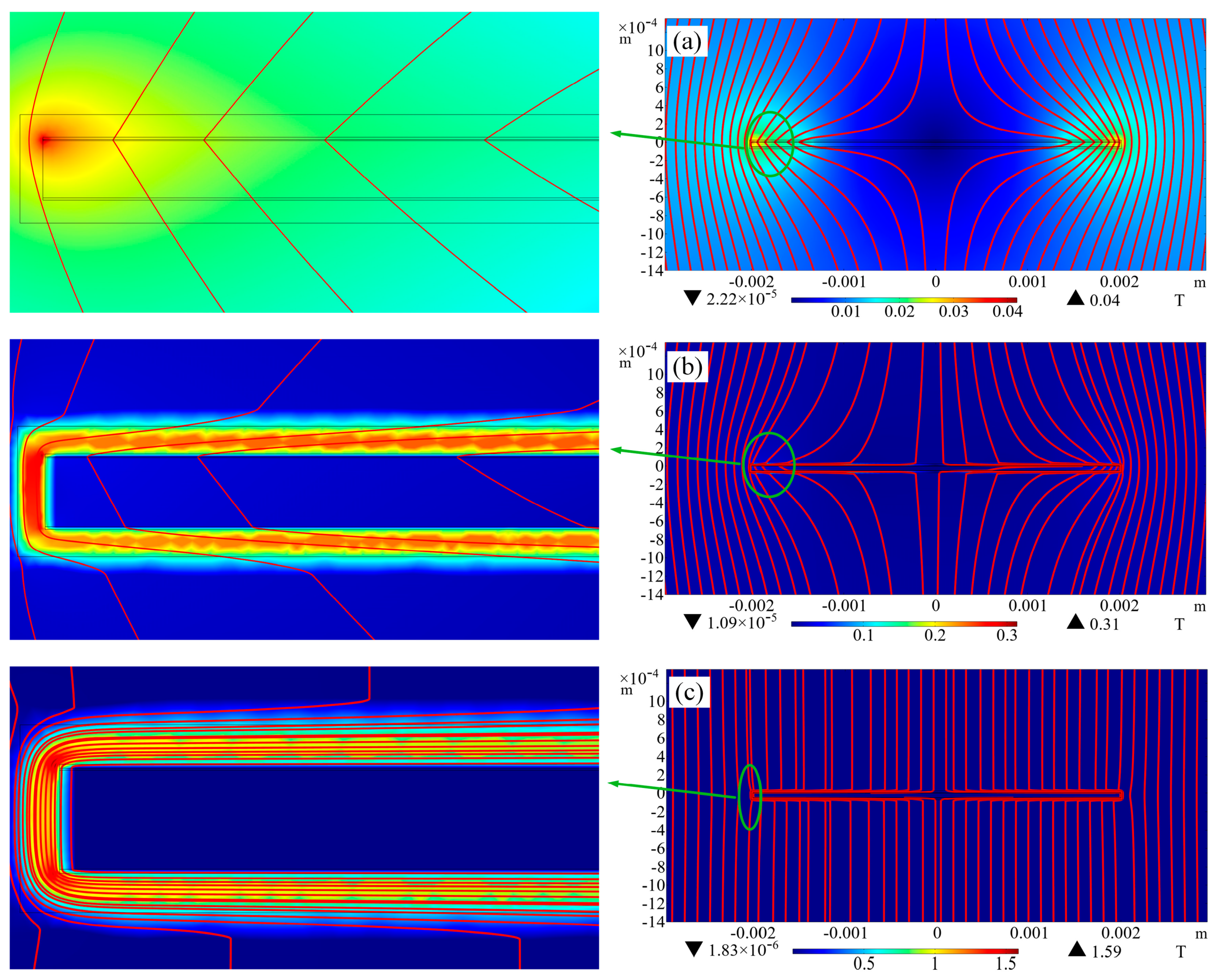
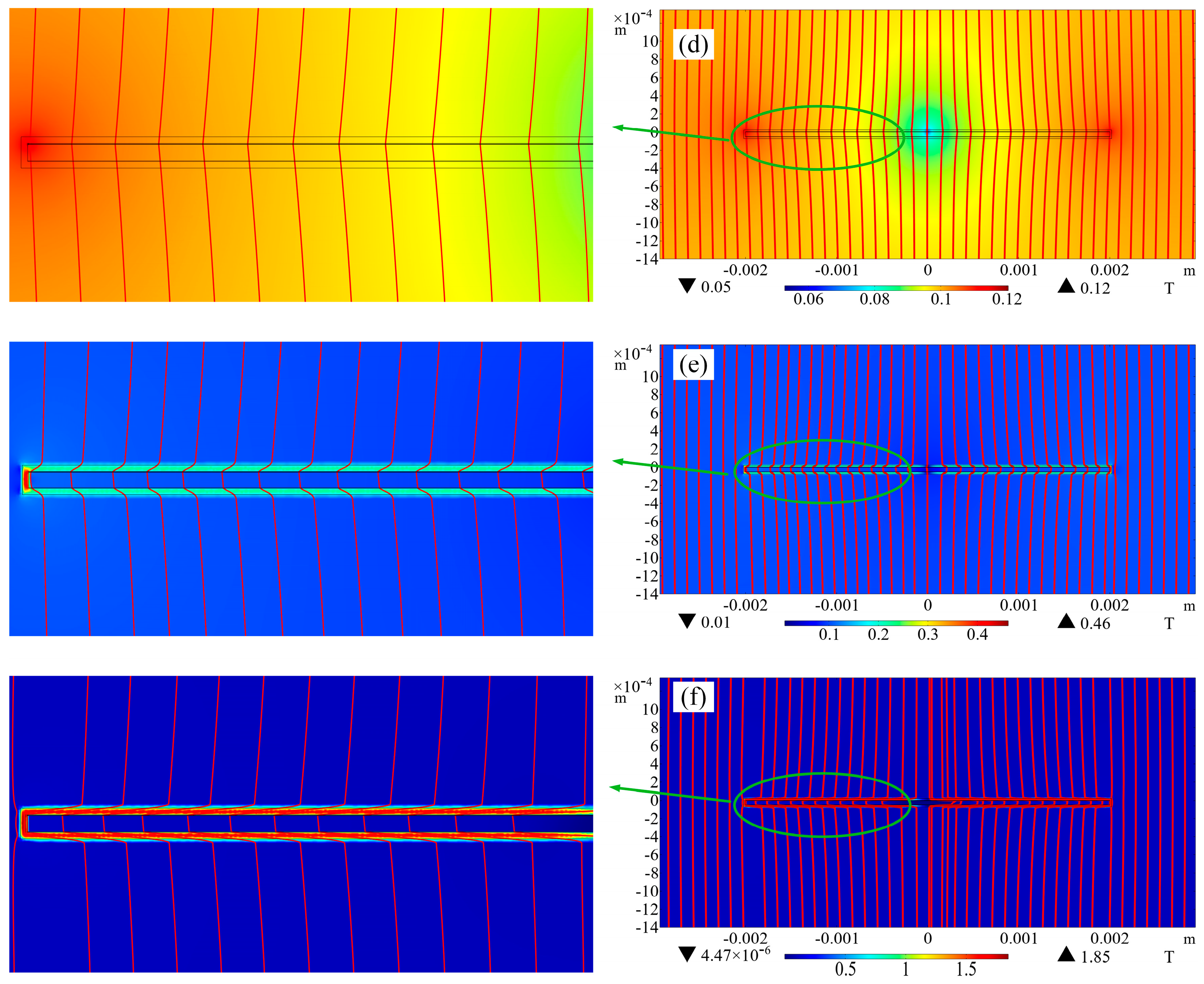
3.2. Magnetization Loss

Figure 5 depicts the change in the magnetization loss of REBCO tapes encapsulated by various materials in the presence of a perpendicular external magnetic field, with a frequency f = 50 Hz. In this case, no transport current is applied to the tape. Figure 5a shows the magnetization loss of each part of the copper-encapsulated tape as a function of the external magnetic field. It is evident that nearly all of the total magnetization loss of the tape stems from the hysteresis loss of the superconducting layer. Moreover, the calculated total magnetization loss of the tape shows a high degree of consistency with the Brandt model [30], which is an analytical solution based on the magnetization loss of an infinitely long thin strip under a perpendicular external magnetic field with Jc as a constant value. The changes in losses within diverse parts of the REBCO tape encapsulated by weak magnetic nickel alloy as the external magnetic field varies are shown in Figure 5b. At this stage, the hysteresis loss of the superconducting layer mainly contributes to the total magnetization loss of the tape. However, it can be seen that at Bext = 0.01 T, the iron loss of the weak magnetic nickel alloy encapsulation layer can also account for 1/10 of the total magnetization loss. The change in losses within different parts of the REBCO tape that is encapsulated by strong magnetic nickel alloy, along with the variation in the external magnetic field, is shown in Figure 5c. At lower external magnetic fields, the total magnetization loss of the tape almost comes from the iron loss of the encapsulation material. At this time, the hysteresis loss of the superconducting layer is very low, mainly because the strong magnetic material has a significant shielding effect on the external magnetic field, resulting in a lower magnetic field entering the superconducting layer and a smaller shielding current density. This will be further explained in Figure 6. In higher external fields, the total magnetization loss of the tape mainly comes from the hysteresis loss of the superconducting layer. Figure 5d shows the total magnetization loss of REBCO tapes encapsulated with three different materials as a function of the external magnetic field. Under the same external magnetic field, copper-encapsulated tapes have higher magnetization losses, while strongly magnetic nickel alloy-encapsulated tapes have the lowest magnetization losses and are more significant at low fields.
The variation in the current density J/Jc of the superconducting layer of REBCO tapes encapsulated by three different materials with respect to the tape width under various external magnetic fields is presented in Figure 6. When Bext = 0.01 T and t = 3/4 cycle, the shielding current density of the copper-encapsulated tape penetrates the deepest, followed by the weakly magnetic nickel alloy-encapsulated tape. The strongly magnetic nickel alloy-encapsulated tape penetrates the least and has a very small J/Jc value. Thus, among all the tapes, the copper-encapsulated tape exhibits the highest magnetization loss, while the tape encapsulated with strongly magnetic nickel alloy has the lowest magnetization loss. When Bext = 0.1 T and t = 3/4 cycle, the shielding current density penetration of the copper-encapsulated tape and the weakly magnetic nickel alloy-encapsulated tape is equivalent, and together, they completely penetrate the entire tape. The strongly magnetic nickel alloy does not completely penetrate the tape. Therefore, at this time, the magnetization loss of the tapes encapsulated by the first two materials is almost equivalent, while the magnetization loss of the strongly magnetic nickel alloy is the smallest.
The distribution of spatial magnetic induction lines of REBCO tapes that are encapsulated with diverse materials under external magnetic fields having different intensities is shown in Figure 7a–c. These correspond to the distribution of magnetic induction lines around copper-encapsulated, weakly magnetic nickel alloy-encapsulated, and strongly magnetic nickel alloy-encapsulated tapes when the external magnetic field Bext = 0.01 T. It can be intuitively seen that the superconducting layer of the copper-encapsulated tape has the deepest penetration of magnetic induction lines, while the weak magnetic nickel alloy-encapsulated tape has a shallower penetration of magnetic induction lines due to the magnetic shielding effect of the magnetic encapsulation layer, and the strong magnetic nickel alloy-encapsulated tape has almost no penetration of magnetic induction lines through the superconducting layer due to its strong magnetic shielding effect. It is precisely due to the difference in spatial distribution of magnetic induction lines that there is a significant difference in hysteresis loss among the superconducting layers of the tape encapsulated by the three materials. Figure 7d–f correspond to the distribution of magnetic induction lines around copper-encapsulated, weakly magnetic nickel alloy-encapsulated, and strongly magnetic nickel alloy-encapsulated tapes when the external magnetic field Bext = 0.1 T. At this point, due to the strong external magnetic field, the magnetic induction lines of the copper- and weakly magnetic nickel alloy-encapsulated tape have completely penetrated the superconducting layer. Due to the strong magnetic shielding effect, the central part of the superconducting layer of the tape encapsulated with strong magnetic nickel alloy has not completely penetrated.
Figure 8 shows the frequency-dependent magnetization loss of REBCO tapes encapsulated with different materials at Bext = 0.05 T. Figure 8a shows the variation in magnetization loss of copper-encapsulated tape with frequency. As the frequency increases, the eddy current loss of the metal layer increases proportionally, while the hysteresis loss of the superconducting layer remains almost unchanged. The total loss of the tape gradually increases. Figure 8b,c show the variation in magnetization loss with frequency for weakly magnetic nickel alloy- and strongly magnetic nickel alloy-encapsulated tapes, respectively. Similarly, as the frequency increases, the eddy current loss of the metal layer increases proportionally, while the hysteresis losses of the superconducting layer and the magnetic encapsulation layer remain almost unchanged. The total loss of the tape slightly increases. Figure 8d presents how the total magnetization loss of REBCO tapes encapsulated by three distinct materials varies with frequency. Within the calculated frequency range, the copper-encapsulated tape has the highest magnetization loss, while the strongly magnetic nickel alloy-encapsulated tape has the lowest magnetization loss.

4. Conclusions

This article investigates the transport loss and magnetization losses of REBCO tapes packaged with different materials using the 2-D H-formulation. At low transport currents, copper-encapsulated tapes have the lowest transport losses, followed by weakly magnetic nickel alloy-encapsulated tapes, while strongly magnetic nickel alloy-encapsulated tapes have the highest transport losses. This is because the iron loss of the magnetic encapsulation layer is greater than the hysteresis loss of the superconducting layer of copper-encapsulated tapes at low transport currents. Under high transport current, the difference in transport loss among the three materials encapsulated in the tape is relatively small. For magnetization loss, the tape encapsulated with strong magnetic nickel alloy has the smallest loss, followed by the tape encapsulated with weak magnetic nickel alloy. The tape encapsulated with copper has the largest magnetization loss, because magnetic materials have the ability to shield external magnetic fields, and strong magnetic nickel alloy has the strongest magnetic shielding ability.

Author Contributions

Conceptualization, Y.B.; methodology, R.J.; software, W.C.; validation, R.J.; formal analysis, F.C. and X.Y.; investigation, R.J.; resources, J.X.; data curation, W.C. and F.C.; writing—original draft preparation, W.C.; writing—review and editing, W.C. and Y.Z.; visualization, W.C. and X.Y.; supervision, R.J. and Y.Z.; project administration, X.Y.; funding acquisition, W.C. All authors have read and agreed to the published version of the manuscript.

Funding

This research was funded by Scientific Research Fund of Zhejiang Provincial Education Department grant number (Y202352232, Y202457308), the Wenzhou Basic Scientific Research Project (G20240061) and the Wenzhou Major Science and Technology Innovation Project (ZG2022008) And The APC was funded by the Scientific Research Fund of Wenzhou University of Technology (ky202309).

Data Availability Statement

The original contributions presented in the study are included in the article, further inquiries can be directed to the corresponding author.

Conflicts of Interest

The authors declare no conflict of interest.

References

  1. Song, W.; Badcock, R.A.; Long, N.J.; Jiang, Z. AC loss in REBCO coil windings wound with various cables: Effect of current distribution among the cable strands. IEEE Access 2023, 11, 102082–102091. [Google Scholar] [CrossRef]
  2. Pi, W.; Li, B.; Zhao, Y.; Li, Z.; Guo, L.; Wang, Y.; Shi, Q. Self-Shielding HTS DC Cable Made by REBCO Tapes with Different Widths. IEEE Trans. Appl. Supercond. 2024, 34, 1–6. [Google Scholar] [CrossRef]
  3. Gao, P.; Guan, M.; Wang, X.; Zhou, Y. Electromagnetic-thermal-structure multi-layer nonlinear elastoplastic modelling study on epoxy-impregnated REBCO pancake coils in high-field magnets. Superconductivity 2022, 1, 100002. [Google Scholar] [CrossRef]
  4. Wang, Y.; Fang, J.; Haugan, T.; Badcock, R.A.; Storey, J.G.; Jiang, Z. Numerical Simulations on the AC loss of REBCO Stacks under Rotating Magnetic Fields. Superconductivity 2024, 11, 100111. [Google Scholar] [CrossRef]
  5. Yang, Y.; Zhang, Z.; Bo, K.; Chen, J. Numerical simulation of AC loss in high-temperature superconducting tapes with strong magnetic field. IEEE Trans. Appl. Supercond. 2024, 34, 1–4. [Google Scholar] [CrossRef]
  6. Hussain, A.; Dadhich, A.; Pardo, E. Thermal quench modeling of REBCO racetrack coils under either alternating current or short-circuit voltage. Supercond. Sci. Technol. 2024, 37, 115028. [Google Scholar] [CrossRef]
  7. Otten, S.; Gačnik, D.; Brüggenwirth, S.; Leferink, J.; Dhallé, M.; Kate, H.T.; Dönges, S.; Weiss, J.; Radcliff, K.; van der Laan, D.; et al. Calculation and Measurement of Transport AC Loss of ReBCO CORC Cables for Electric Aircraft. IEEE Trans. Appl. Supercond. 2024, 34, 1–5. [Google Scholar] [CrossRef]
  8. Luo, X.; Ma, J.; Xiao, H.; Zhang, Z.; Yuan, C. Multiphysics multilayer modelling and simulation of HTS REBCO magnets carrying direct currents under AC magnetic fields. Superconductivity 2025, 14, 100157. [Google Scholar] [CrossRef]
  9. Liu, G.; Zhang, G.; Jing, L. Experimental and numerical study of the frequency-dependent transport ac losses of the YBa2Cu3O7−δ coil with and without flux diverters. Supercond. Sci. Technol. 2019, 32, 055002. [Google Scholar] [CrossRef]
  10. Gömöry, F.; Vojenčiak, M.; Pardo, E.; Šouc, J. Magnetic flux penetration and AC loss in a composite superconducting wire with ferromagnetic parts. Supercond. Sci. Technol. 2009, 22, 034017. [Google Scholar] [CrossRef]
  11. Ma, G.T.; Rauh, H. Thermo-electromagnetic properties of a magnetically shielded superconductor strip: Theoretical foundations and numerical simulations. Supercond. Sci. Technol. 2013, 26, 105001. [Google Scholar] [CrossRef]
  12. Vojenčiak, M.; Šouc, J.; Gömöry, F. Critical current and AC loss analysis of a superconducting power transmission cable with ferromagnetic diverters. Supercond. Sci. Technol. 2011, 24, 075001. [Google Scholar] [CrossRef]
  13. Liu, G.; Zhang, G.; Jing, L.; Yu, H. Numerical study on AC loss reduction of stacked HTS tapes by optimal design of flux diverter. Supercond. Sci. Technol. 2017, 30, 125014. [Google Scholar] [CrossRef]
  14. Chen, W.; Jin, R.; Wang, S.; Xu, M.; Che, T.; Shen, B.; Yang, X.; Zhao, Y. The effect of flux diverters on the AC loss of REBCO coil coupled with iron core. Cryogenics 2022, 128, 103573. [Google Scholar] [CrossRef]
  15. Wu, Y.; You, S.; Fang, J.; Badcock, R.A.; Long, N.J.; Jiang, Z. AC loss study on a 3-phase HTS 1 MVA transformer coupled with a three-limb iron core. Superconductivity 2024, 10, 100095. [Google Scholar] [CrossRef]
  16. Wu, Y.; Fang, J.; Miyagi, D.; Amemiya, N.; Badcock, R.A.; Long, N.J.; Jiang, Z. Experimental AC loss study on REBCO coil assemblies coupled with an iron cylinder. Supercond. Sci. Technol. 2024, 37, 055010. [Google Scholar] [CrossRef]
  17. You, S.; Miyagi, D.; Badcock, R.A.; Long, N.J.; Jiang, Z. Experimental and numerical study on AC loss reduction in a REBCO coil assembly by applying high saturation field powder-core flux diverters. Cryogenics 2022, 124, 103466. [Google Scholar] [CrossRef]
  18. Liu, G.; Zhang, G.; Liu, G.; Wang, H.; Jing, L. Transport AC loss characteristic of YBa2Cu3 O7-δ coils with and without magnetic substrate up to 10 kHz. IEEE Trans. Appl. Supercond. 2023, 33, 1–8. [Google Scholar]
  19. Chen, W.; Jin, R.; Chi, F.; Ye, Y.; Wang, W.; Yang, X.; Zhu, Y.; Cai, L.; Sun, X.; Li, X. Study on AC loss of stacked REBCO cable wrapped with magnetic strip. Cryogenics 2024, 144, 103975. [Google Scholar] [CrossRef]
  20. Jiang, Z.; Song, H.; Song, W.; Badcock, R.A. Optimizing coil configurations for AC loss reduction in REBCO HTS fast-ramping magnets at cryogenic temperatures. Superconductivity 2022, 3, 100024. [Google Scholar] [CrossRef]
  21. Wu, Y.; Fang, J.; Amemiya, N.; Badcock, R.A.; Long, N.J.; Jiang, Z. AC loss reduction in HTS coil windings coupled with an iron core using flux diverters. IEEE Access 2023, 11, 48826–48840. [Google Scholar] [CrossRef]
  22. Zhang, H.; Wen, Z.; Grilli, F.; Gyftakis, K.; Mueller, M. Alternating current loss of superconductors applied to superconducting electrical machines. Energies 2021, 14, 2234. [Google Scholar] [CrossRef]
  23. Shen, B.; Grilli, F.; Coombs, T. Overview of H-formulation: A versatile tool for modeling electromagnetics in high-temperature superconductor applications. IEEE Access 2020, 8, 100403–100414. [Google Scholar] [CrossRef]
  24. Shen, B.; Grilli, F.; Coombs, T. Review of the AC loss computation for HTS using H formulation. Supercond. Sci. Technol. 2020, 33, 033002. [Google Scholar] [CrossRef]
  25. Niu, M.; Yong, H.; Xia, J.; Zhou, Y. The effects of ferromagnetic disks on AC losses in HTS pancake coils with nonmagnetic and magnetic substrates. J. Supercond. Nov. Magn. 2019, 32, 499–510. [Google Scholar] [CrossRef]
  26. Zhou, P.; Ma, G.; Quéval, L. Transition frequency of transport ac losses in high temperature superconducting coated conductors. J. Appl. Phys. 2019, 126, 063901. [Google Scholar] [CrossRef]
  27. Zhou, P.; Wang, C.; Qian, H.; Quéval, L.; Luo, Z.; Deng, Y. Frequency-dependent transport AC losses of coated superconductors up to tens of kilohertz. IEEE Trans. Appl. Supercond. 2019, 29, 1–5. [Google Scholar] [CrossRef]
  28. Norris, W.T. Calculation of hysteresis losses in hard superconductors carrying ac: Isolated conductors and edges of thin sheets. J. Phys. D Appl. Phys. 1970, 3, 489–507. [Google Scholar] [CrossRef]
  29. Gömöry, F.; Šouc, J.; Vojenčiak, M.; Alamgir, A.K.M.; Han, Z.; Gu, C. Reduction of ac transport and magnetization loss of a high-Tc superconducting tape by placing soft ferromagnetic materials at the edges. Appl. Phys. Lett. 2007, 90, 092506. [Google Scholar] [CrossRef]
  30. Brandt, E.H.; Indenbom, M. Type-II-superconductor strip with current in a perpendicular magnetic field. Phys. Rev. B 1993, 48, 12893. [Google Scholar] [CrossRef]
Figure 1. (a) Copper-encapsulated REBCO tape; (b) REBCO tapes encapsulated with magnetic materials.
Crystals 15 00407 g001
Figure 2. Transport loss of various parts of REBCO tapes encapsulated with different materials as a function of transport current: (a) copper encapsulation; (b) weak magnetic material encapsulation; (c) strong magnetic material encapsulation; (d) comparison of the total transport loss of the whole tape.
Crystals 15 00407 g002
Figure 3. When t = 3/4 cycle, Ip/Ic0 = 0.1 and Ip/Ic0 = 0.9, the transport current density of the superconducting layer varies with the width of the tape.
Crystals 15 00407 g003
Figure 4. When Ip/Ic0 = 0.4, the transport loss of various parts of REBCO tapes encapsulated with different materials vary with frequency: (a) copper encapsulation; (b) weak magnetic material encapsulation; (c) strong magnetic material encapsulation; (d) comparison of the total transport loss of the whole tape.
Crystals 15 00407 g004
Figure 5. Magnetization loss of various parts of REBCO tapes encapsulated with different materials as a function of alternating magnetic field: (a) copper encapsulation; (b) weak magnetic material encapsulation; (c) strong magnetic material encapsulation; (d) comparison of the total magnetization loss of the whole tape.
Crystals 15 00407 g005
Figure 6. When t = 3/4 cycle, Bext = 0.01 T and Bext = 0.1 T, the shielding current density of the superconducting layer varies with the width of the tape.
Crystals 15 00407 g006
Figure 7. The magnetic induction line distribution of REBCO tapes encapsulated with different materials at t = 3/4 cycle; (ac) for Bext = 0.01 T, copper-, weak magnetic material-, and strong magnetic material-encapsulated tapes; (df) for Bext = 0.1 T, copper-, weak magnetic material-, and strong magnetic material-encapsulated tapes.
Crystals 15 00407 g007aCrystals 15 00407 g007b
Figure 8. When Bext = 0.05 T, the magnetization loss of various parts of REBCO coated conductor encapsulated with different materials vary with frequency: (a) copper encapsulation; (b) weak magnetic material encapsulation; (c) strong magnetic material encapsulation; (d) comparison of the total magnetization loss of the whole tape.
Crystals 15 00407 g008
Table 1. Relevant parameters used in numerical calculation [14,26,27].
ParametersValue
Jc0 (77 K, self-field) [A/m2]2.85 × 1010
k0.25
B0 [mT]52.5
α0.7
Ec [μV/cm]1
n32
ρcopper (77 K) [Ω·m]1.97 × 10⁻⁹
ρsilver (77 K) [Ω·m]2.7 × 10⁻⁹
ρhastelloy (77 K) [Ω·m]1250 × 10−9
ρweak magnetic materials (77 K) [Ω·m]63 × 10−9
ρstrong magnetic materials (77 K) [Ω·m]1300 × 10−9
Disclaimer/Publisher’s Note: The statements, opinions and data contained in all publications are solely those of the individual author(s) and contributor(s) and not of MDPI and/or the editor(s). MDPI and/or the editor(s) disclaim responsibility for any injury to people or property resulting from any ideas, methods, instructions or products referred to in the content.

