Analysis of O-Ring Seal Failure under Static Conditions and Determination of End-of-Lifetime Criterion


Abstract
:
1. Introduction
2. Materials and Methods
3. Results and Discussion
3.1. Dynamic-Mechanical Analysis (DMA)
3.2. Permeability
3.3. Static Leakage Rate Measurements
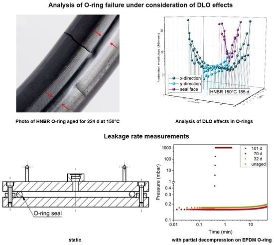
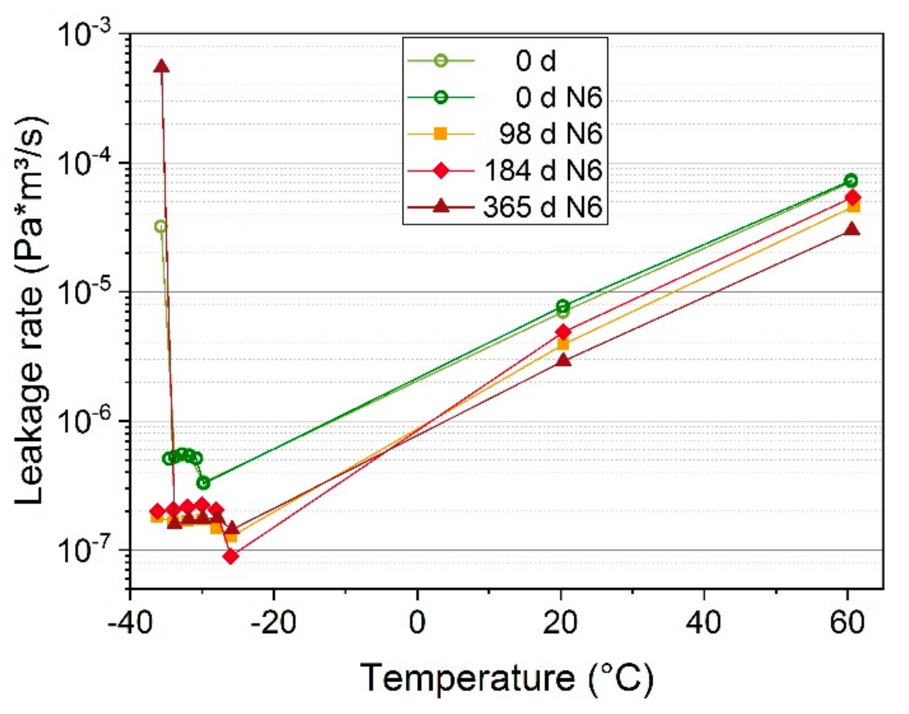
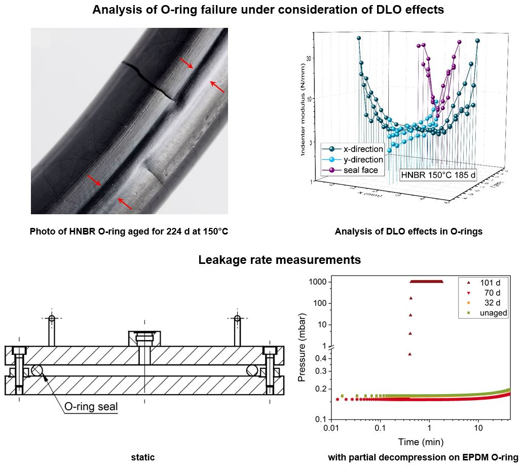
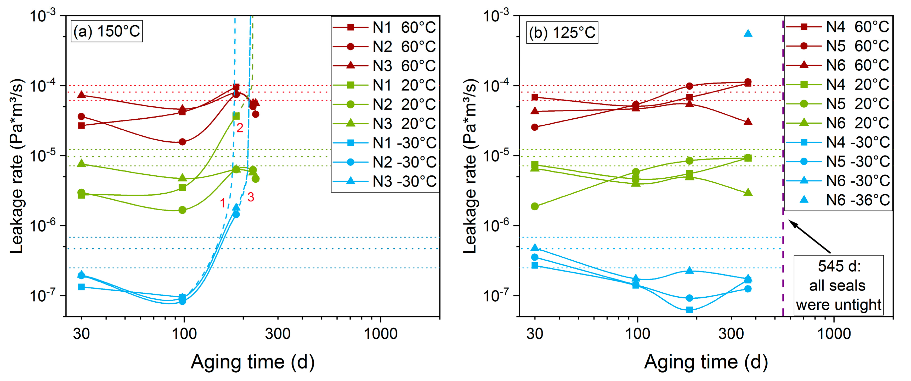
3.3.1. HNBR
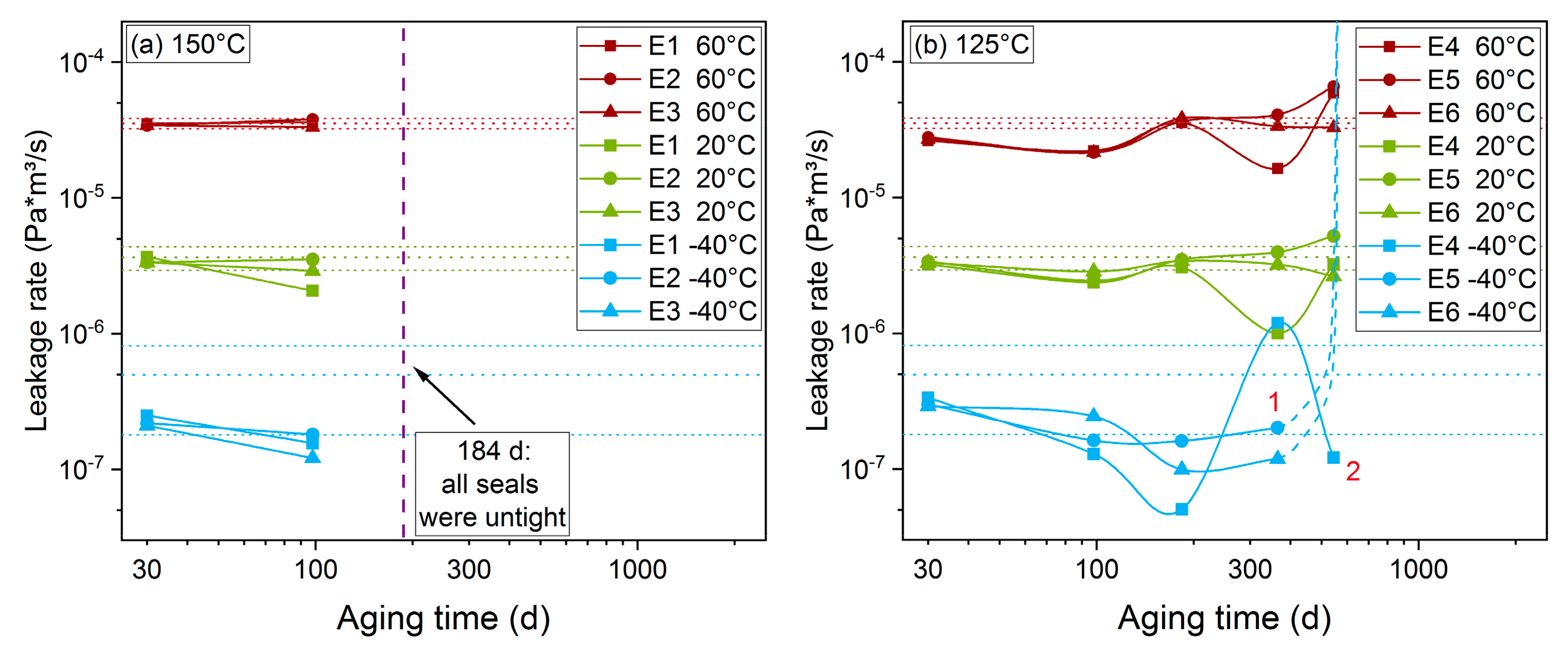
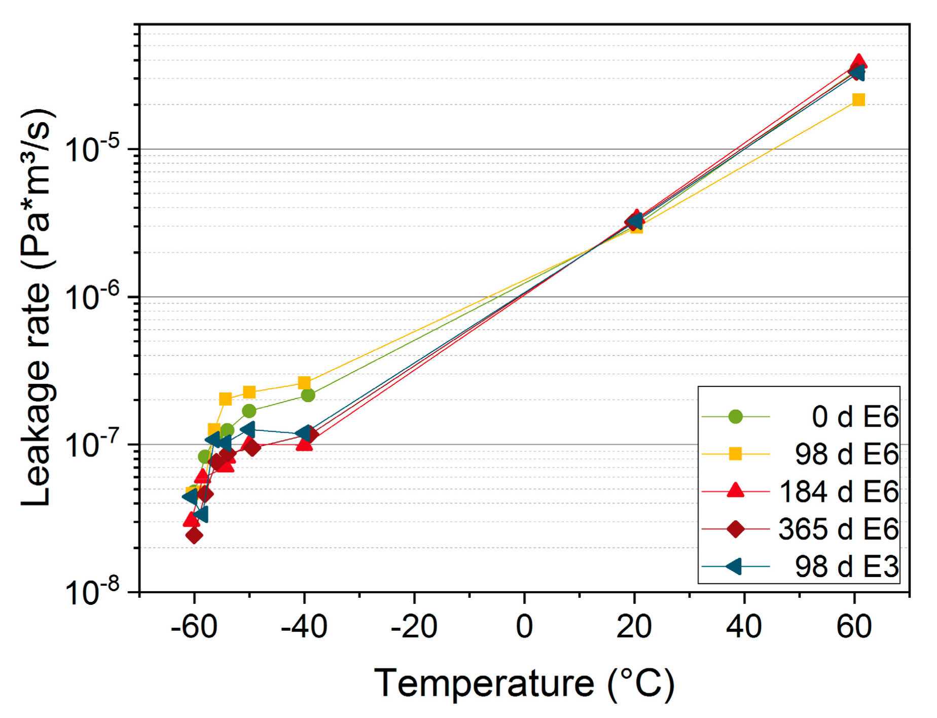
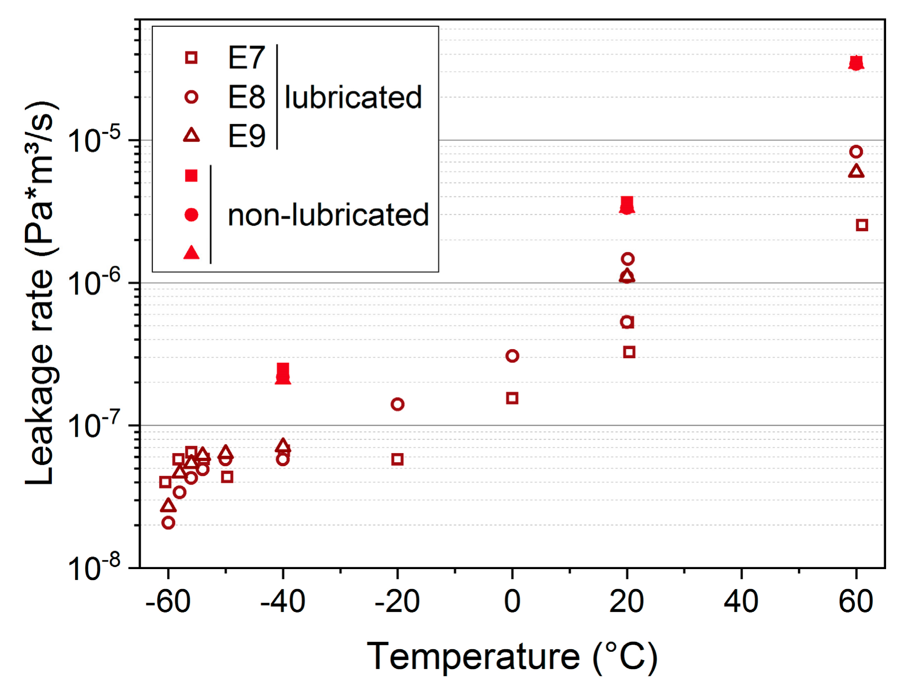
3.3.2. EPDM
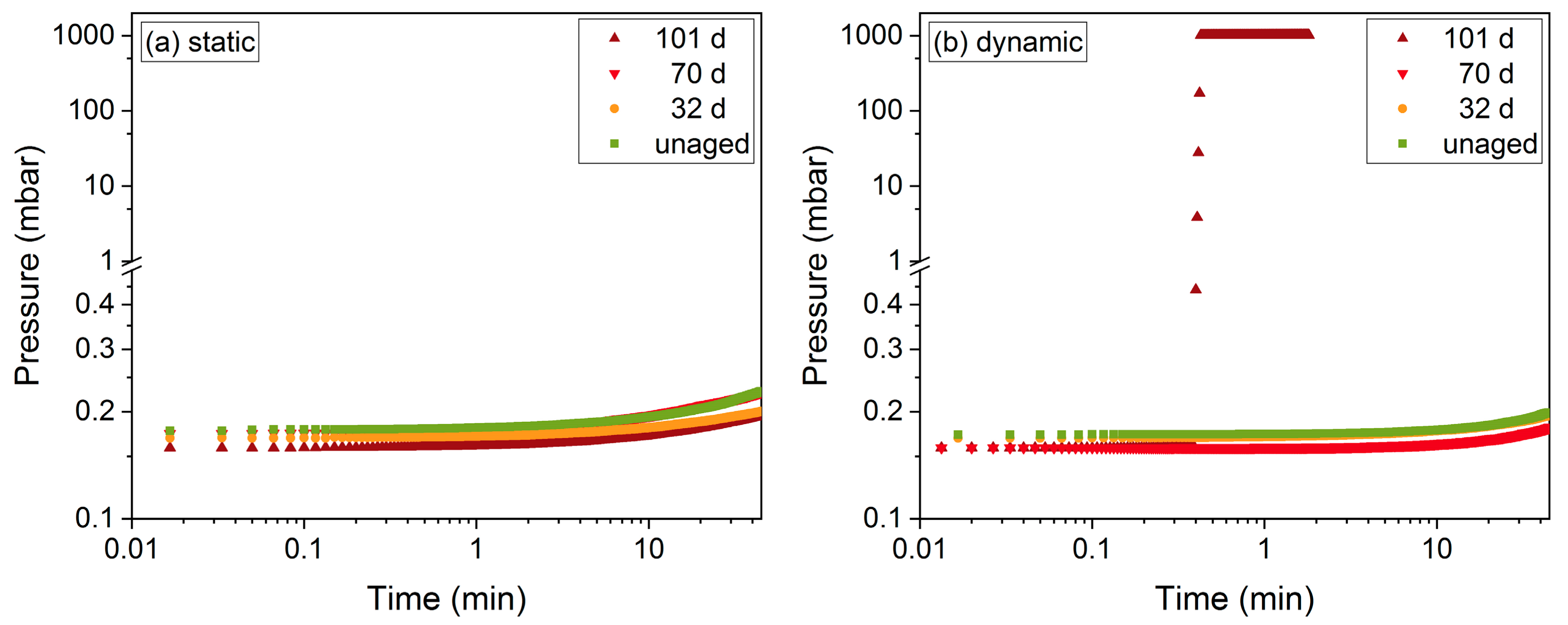
3.4. Influence of Diffusion-Limited Oxidation (DLO) Effects on Leak-Tightness
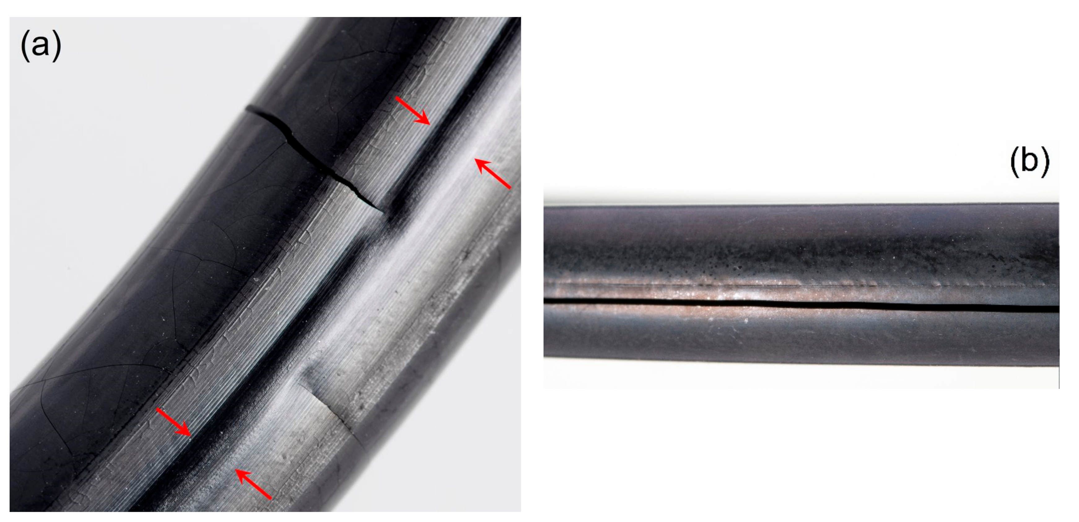
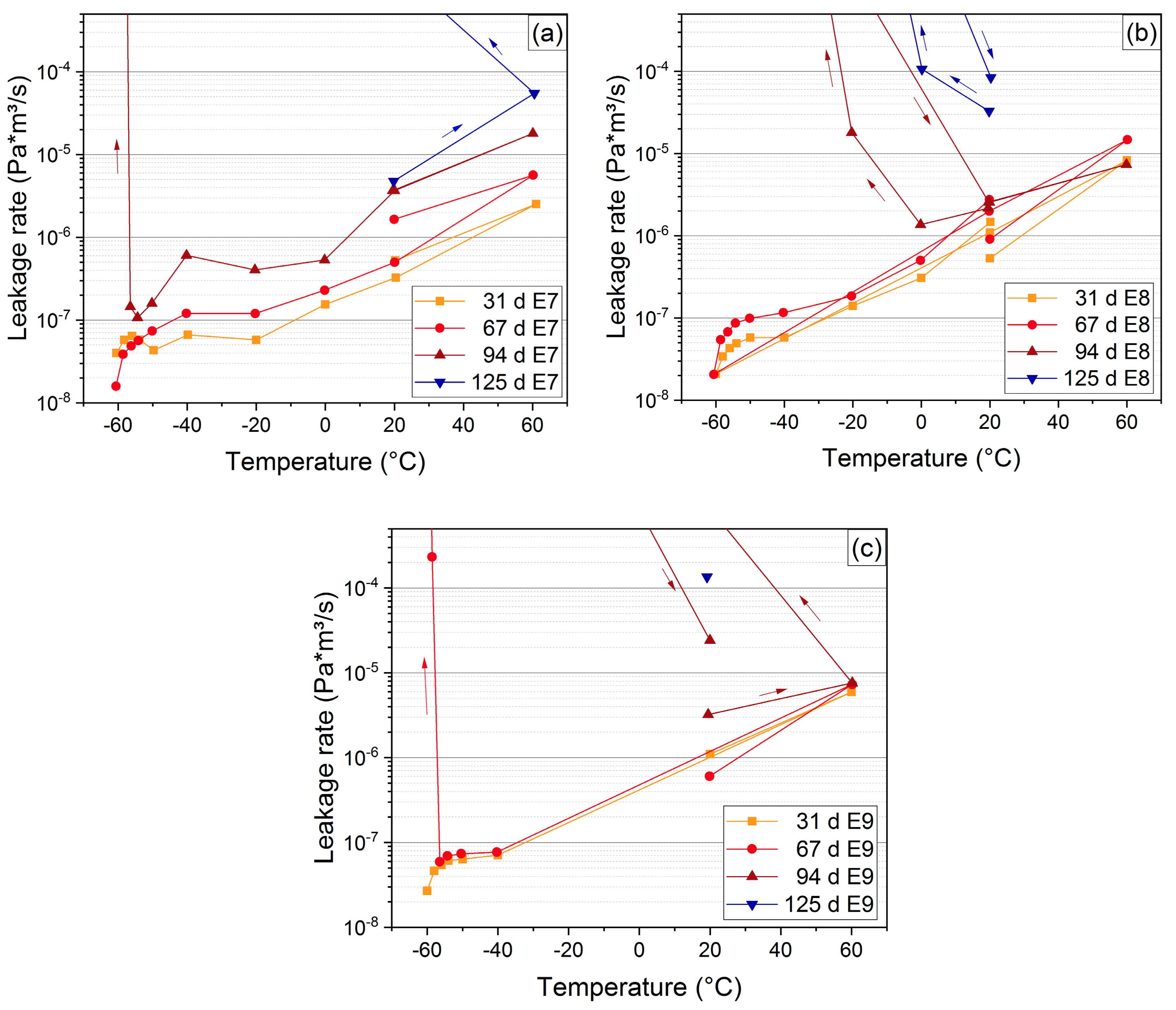
3.5. Influence of Sticking/Lubricant
3.6. Determination of End-of-Lifetime Criterion
4. Conclusions
Author Contributions
Funding
Acknowledgments
Conflicts of Interest
References
- Curro, J.G.; Pincus, P. A theoretical basis for viscoelastic relaxation of elastomers in the long-time limit. Macromolecules 1983, 16, 559–562. [Google Scholar] [CrossRef]
- Hutchinson, J.M. Physical aging of polymers. Prog. Polym. Sci. 1995, 20, 703–760. [Google Scholar] [CrossRef]
- Lou, W.; Zhang, W.; Jin, T.; Liu, X.; Wang, H. Stress–thermal oxidative aging behavior of hydrogenated nitrile rubber seals. J. Appl. Polym. Sci. 2019, 136, 47014. [Google Scholar] [CrossRef]
- Lou, W.; Zhang, W.; Jin, T.; Liu, X.; Dai, W. Synergistic Effects of Multiple Environmental Factors on Degradation of Hydrogenated Nitrile Rubber Seals. Polymers 2018, 10, 897. [Google Scholar] [CrossRef] [PubMed]
- Chen, S.; Yu, H.; Ren, W.; Zhang, Y. Thermal degradation behavior of hydrogenated nitrile-butadiene rubber (HNBR)/clay nanocomposite and HNBR/clay/carbon nanotubes nanocomposites. Thermochim. Acta 2009, 491, 103–108. [Google Scholar] [CrossRef]
- Zhu, Z.; Jiang, C.; Cheng, Q.; Zhang, J.; Guo, S.; Xiong, Y.; Fu, B.; Yang, W.; Jiang, H. Accelerated aging test of hydrogenated nitrile butadiene rubber using the time-temperature-strain superposition principle. RSC Adv. 2015, 5, 90178–90183. [Google Scholar] [CrossRef]
- Pourmand, P.; Hedenqvist, M.S.; Furo, I.; Gedde, U.W. Deterioration of highly filled EPDM rubber by thermal ageing in air: Kinetics and non-destructive monitoring. Polym. Test. 2017, 64, 267–276. [Google Scholar] [CrossRef]
- Landi, V.R.; Easterbrook, E.K. Scission and crosslinking during oxidation of peroxide cured EPDM. Polym. Eng. Sci. 1978, 18, 1135–1143. [Google Scholar] [CrossRef]
- Gillen, K.; Wise, J.; Celina, M.; Clough, R. Evidence that Arrhenius High-Temperature Aging Behavior for an EPDM O-Ring Does not Extrapolate to Lower Temperatures; Report Sandia National Labs: Albuquerque, NM, USA, 1997. [Google Scholar]
- Gamlin, C.; Dutta, N.; Roy-Choudhury, N.; Kehoe, D.; Matisons, J. Influence of ethylene–propylene ratio on the thermal degradation behaviour of EPDM elastomers. Thermochim. Acta 2001, 367–368, 185–193. [Google Scholar] [CrossRef]
- De Almeida, A.; Chazeau, L.; Vigier, G.; Marque, G.; Goutille, Y. Influence of PE/PP ratio and ENB content on the degradation kinetics of γ-irradiated EPDM. Polym. Degrad. Stab. 2014, 110, 175–183. [Google Scholar] [CrossRef]
- Pourmand, P.; Linde, E.; Hedenqvist, M.S.; Furó, I.; Dvinskikh, S.V.; Gedde, U.W. Profiling of thermally aged EPDM seals using portable NMR, indenter measurements and IR spectroscopy facilitating separation of different deterioration mechanisms. Polym. Test. 2016, 53, 77–84. [Google Scholar] [CrossRef]
- Gillen, K.T.; Keenan, M.R.; Wise, J. New method for predicting lifetime of seals from compression-stress relaxation experiments. Die Angew. Makromol. Chem. 1998, 261–262, 83–92. [Google Scholar] [CrossRef]
- Momon, S.; Garcia, J.; Issard, H. Leak tightness of O-rings for transport of radioactive material. Packag. Transp. Storage Secur. Radioact. Mater. 2013, 24, 3–9. [Google Scholar] [CrossRef]
- Gillen, K.T.; Bernstein, R.; Wilson, M.H. Predicting and confirming the lifetime of o-rings. Polym. Degrad. Stab. 2005, 87, 257–270. [Google Scholar] [CrossRef]
- Tobolsky, A.V.; Frick, N.H.; Norling, P.M.; Yu, H. On Mechanism of Autoxidation of three vinyl Polymers—Polypropylene, Ethylene-Propylene Rubber and Poly (Ethyl Acrylate). J. Am. Chem. Soc. 1964, 86, 3925–3930. [Google Scholar] [CrossRef]
- Bender, H.; Campomizzi, E. Improving the heat resistance of hydrogenated nitrile rubber compounds. KGK 2001, 54, 14–21. [Google Scholar]
- Liu, X.; Zhao, J.; Yang, R.; Iervolino, R.; Barbera, S.J.P. Thermal aging of hydrogenated nitrile rubber–loss of additives and its influence on elasticity maintenance. Polimery 2017, 62, 588–598. [Google Scholar] [CrossRef]
- Ehrenstein, G.W.; Pongratz, S. Beständigkeit von Kunststoffen; Hanser: Munich, Germany, 2007. [Google Scholar]
- ISO 11346:2004. Rubber, Vulcanized or Thermoplastic—Estimation of Life-Time and Maximum Temperature of Use; ISO: Geneva, Switzerland, 2004. [Google Scholar]
- Numata, K.; Kurokawa, H.; Kawaguchi, S.; Sekine, S.; Nakazawa, Y.; Asano, A. Evaluation of sealability for aged rubber seals by spin–spin relaxation time. Polym. Test. 2016, 49, 147–155. [Google Scholar] [CrossRef]
- Mostafa, A.; Abouel-Kasem, A.; Bayoumi, M.R.; El-Sebaie, M.G. Effect of carbon black loading on the swelling and compression set behavior of SBR and NBR rubber compounds. Mater. Des. 2009, 30, 1561–1568. [Google Scholar] [CrossRef]
- Burnay, S.G.; Hitchon, J.W. Prediction of service lifetimes of elastomeric seals during radiation ageing. J. Nucl. Mater. 1985, 131, 197–207. [Google Scholar] [CrossRef]
- Placek, V.; Kohout, T.; Hnat, V.; Bartonicek, B. Assessment of the EPDM seal lifetime in nuclear power plants. Polym. Test 2009, 28, 209–214. [Google Scholar] [CrossRef]
- Kömmling, A.; Jaunich, M.; Pourmand, P.; Wolff, D.; Gedde, U.W. Influence of Ageing on Sealability of Elastomeric O-Rings. Macromo. Symp. 2017, 373, 1600157. [Google Scholar] [CrossRef]
- Grelle, T.; Wolff, D.; Jaunich, M. Temperature-dependent leak tightness of elastomer seals after partial and rapid release of compression. Polym. Test. 2015, 48, 44–49. [Google Scholar] [CrossRef]
- Crank, J. The Mathematics of Diffusion; Clarendon Press: Oxford, UK, 1979. [Google Scholar]
- Hao, N.; Böhning, M.; Schönhals, A. CO2 gas transport properties of nanocomposites based on polyhedral oligomeric phenethyl-silsesquioxanes and poly (bisphenol A carbonate). Macromolecules 2010, 43, 9417–9425. [Google Scholar] [CrossRef]
- IEC/IEEE International Standard 62582-2:2011-8 Edition 1.0. Part 2: Indenter modulus. In Nuclear Power Plants-Instrumentation and Control Important to Safety—Electrical Equipment Condition Monitoring Methods; DIN: New York, NY, USA, 2011.
- Salame, M.; Steingiser, S. Barrier polymers. Polym.-Plast. Technol. Eng. 1977, 8, 155–175. [Google Scholar] [CrossRef]
- Gülmüs, S.A.; Yilmaz, L. Effect of temperature and membrane preparation parameters on gas permeation properties of polymethacrylates. J. Polym. Sci. Part B Polym. Phys. 2007, 45, 3025–3033. [Google Scholar] [CrossRef]
- Jaunich, M.; Wolff, D.; Stark, W. Low Temperature Properties of Rubber Seals—Results of Component Tests. KGK 2013, 66, 26–30. [Google Scholar]
- Kömmling, A.; Jaunich, M.; Wolff, D. Effects of heterogeneous aging in compressed HNBR and EPDM O-ring seals. Polym. Degrad. Stab. 2016, 126, 39–46. [Google Scholar] [CrossRef]
- Fang, B.; Kang, H.; Wang, R.; Wang, Z.; Wang, W.; Zhang, L. Aging behavior and mechanism of bio-based engineering polyester elastomer nanocomposites. J. Appl. Polym. Sci. 2014, 131. [Google Scholar] [CrossRef]
- Parker O-Ring Handbook; Parker Hannifin Corporation: Cleveland, OH, USA, 2018.
- Jaunich, M.; Kömmling, A.; Horn, J.; Völzke, H.; Wolff, D. Long-Term Performance of Elastomer seals—From Aging Tests to Lifetime Estimations. In Proceedings of the ASME Pressure Vessels and Piping Conference, Prague, Czech, Republic, 15–20 July 2018. [Google Scholar]
- Kömmling, A.; Jaunich, M.; Wolff, D. Ageing and Lifetime Prediction of O-ring Seals made of HNBR, EPDM and FKM. In Proceedings of the KHK Fall Rubber Colloquium, Hanover, Germany, 22–24 November 2016. [Google Scholar]
- DIN ISO 815:2010. Part 1: At ambient or elevated temperatures. DIN: Berlin, Germany; ISO: Geneva, Switzerland, 2010. [Google Scholar]
- DIN ISO 3384:2008. Part 1: Testing at constant temperature. In Rubber, Vulcanized or Thermoplastic—Determination of Stress Relaxation in Compression; DIN: Berlin, Germany; ISO: Geneva, Switzerland, 2008. [Google Scholar]
- DIN EN ISO 527-1:2012. Part 1: General principles. In Plastics—Determination of Tensile Properties; DIN: Berlin, Germany; EN: Brussels, Belgium; ISO: Geneva, Switzerland, 2012. [Google Scholar]
- DIN EN ISO 868:2003. Plastics and Ebonite—Determination of Indentation Hardness by Means of a Durometer (Shore Hardness); DIN: Berlin, Germany; EN: Brussels, Belgium; ISO: Geneva, Switzerland, 2003. [Google Scholar]


| Seal Label | Material | Aging Temp. | Lubricated |
|---|---|---|---|
| N1, N2, N3 | HNBR | 150 °C | No |
| N4, N5, N6 | HNBR | 125 °C | No |
| E1, E2, E3 | EPDM | 150 °C | No |
| E4, E5, E6 | EPDM | 125 °C | No |
| E7, E8, E9 | EPDM | 150 °C | Yes |
| Measurement | Material | Aging Temp. | Aging Times (+Unaged) | Sample Geometry |
|---|---|---|---|---|
| DMA | HNBR | 125 °C, 150 °C | 30 d to 1 a | 2.5 mm diameter disks from 2 mm thick sheets |
| EPDM | 125 °C, 150 °C | 30 d to 1.5 a | ||
| Oxygen permeability | HNBR | 150 °C | 10 d | 0.2–0.3 mm thick sheets with 38 mm diameter |
| EPDM | 150 °C | 10 d, 30 d | ||
| Indenter Modulus | HNBR, EPDM | 150 °C | 100 d, 0.5 a | half O-rings aged in compression |
| Static leakage rate | HNBR, EPDM | 125 °C, 150 °C | 30 d to 1.5 a | O-rings aged in compression |
| Static leakage rate with lubricated seals | EPDM | 150 °C | 30 d to 125 d | |
| Leakage rate with partial decompression | EPDM | 150 °C | 30 d to 100 d |
| E7 | E8 | E9 |
|---|---|---|
| 20 | 20 | 20 |
| 60 | 0 | 60 |
| 20 | −20 | −40 |
| 0 | −40 | −50 |
| −20 | −50 | −54 |
| −40 | −54 | −56 |
| −50 | −56 | −58 |
| −54 | −58 | −60 |
| −56 | −60 | |
| −58 | 20 | |
| −60 | 60 |
| Change after 70 d at 150 °C | Method/Property | Measurement/Standard | Sample Geometry |
|---|---|---|---|
| +89% | Compression set | DIN ISO 815-1 [38] | Half O-rings |
| −86% | Compression stress relaxation | DIN ISO 3384 [39] | 4 cm O-ring segments |
| −91% | Elongation at break | DIN EN ISO 527-1 1 [40] | S2 samples |
| −46% | Maximum loss factor | DMA peak tan δ at 1 Hz | 2.5 mm diameter disks from 2 mm thick sheets |
| +5 °C | Glass transition temperature | DMA peak E″ at 1 Hz | |
| +6 | Shore A hardness | DIN EN ISO 868 [41] | Uncompressed O-ring |
© 2019 by the authors. Licensee MDPI, Basel, Switzerland. This article is an open access article distributed under the terms and conditions of the Creative Commons Attribution (CC BY) license (http://creativecommons.org/licenses/by/4.0/).
Share and Cite
Kömmling, A.; Jaunich, M.; Pourmand, P.; Wolff, D.; Hedenqvist, M. Analysis of O-Ring Seal Failure under Static Conditions and Determination of End-of-Lifetime Criterion. Polymers 2019, 11, 1251. https://doi.org/10.3390/polym11081251
Kömmling A, Jaunich M, Pourmand P, Wolff D, Hedenqvist M. Analysis of O-Ring Seal Failure under Static Conditions and Determination of End-of-Lifetime Criterion. Polymers. 2019; 11(8):1251. https://doi.org/10.3390/polym11081251
Chicago/Turabian StyleKömmling, Anja, Matthias Jaunich, Payam Pourmand, Dietmar Wolff, and Mikael Hedenqvist. 2019. "Analysis of O-Ring Seal Failure under Static Conditions and Determination of End-of-Lifetime Criterion" Polymers 11, no. 8: 1251. https://doi.org/10.3390/polym11081251
APA StyleKömmling, A., Jaunich, M., Pourmand, P., Wolff, D., & Hedenqvist, M. (2019). Analysis of O-Ring Seal Failure under Static Conditions and Determination of End-of-Lifetime Criterion. Polymers, 11(8), 1251. https://doi.org/10.3390/polym11081251