Low Dielectric Constant Polyimide Obtained by Four Kinds of Irradiation Sources


Abstract
: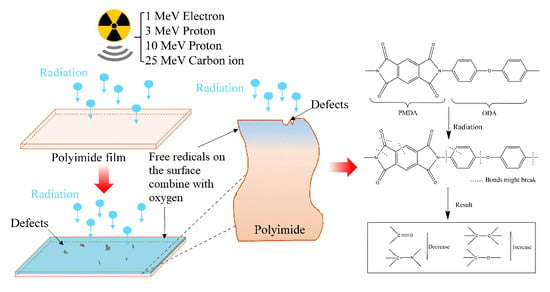
1. Introduction
2. Experimental Section
2.1. Materials and Equipment
2.2. Experimental Parameter
2.3. Characterizations
3. Results
3.1. Dielectric Constant Analysis
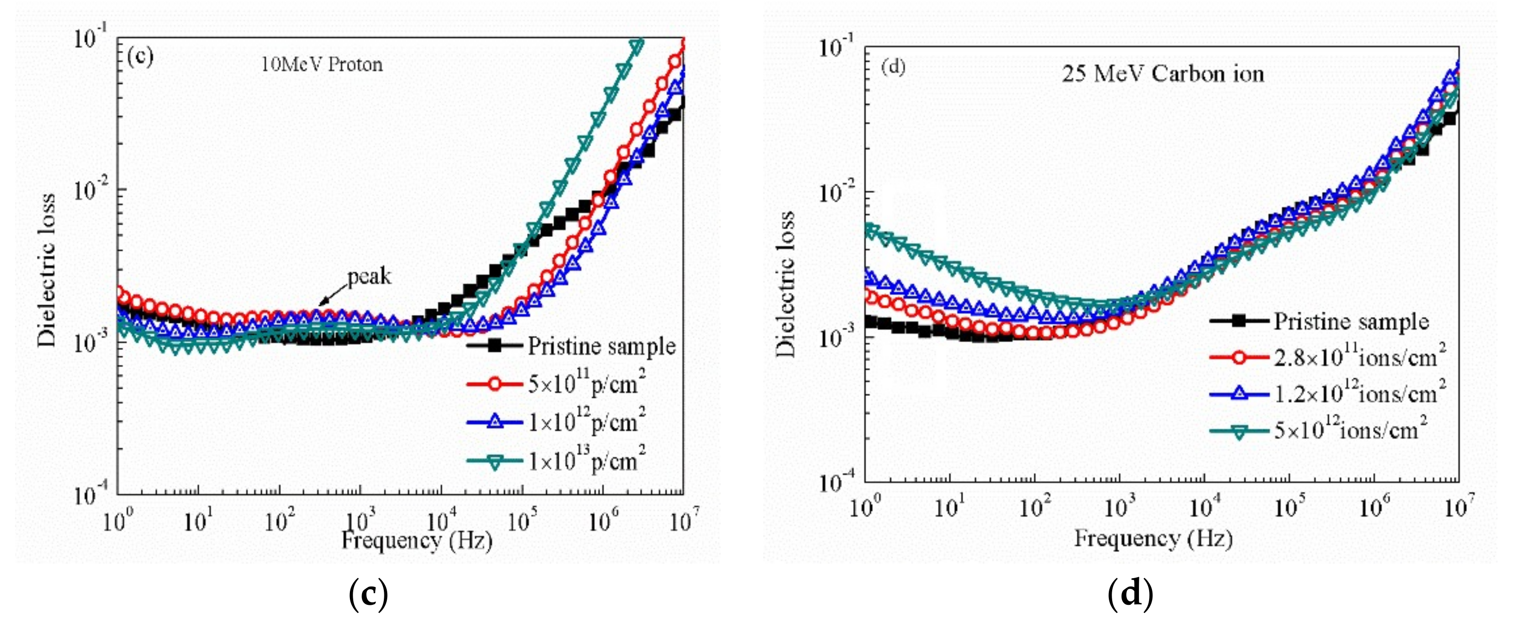
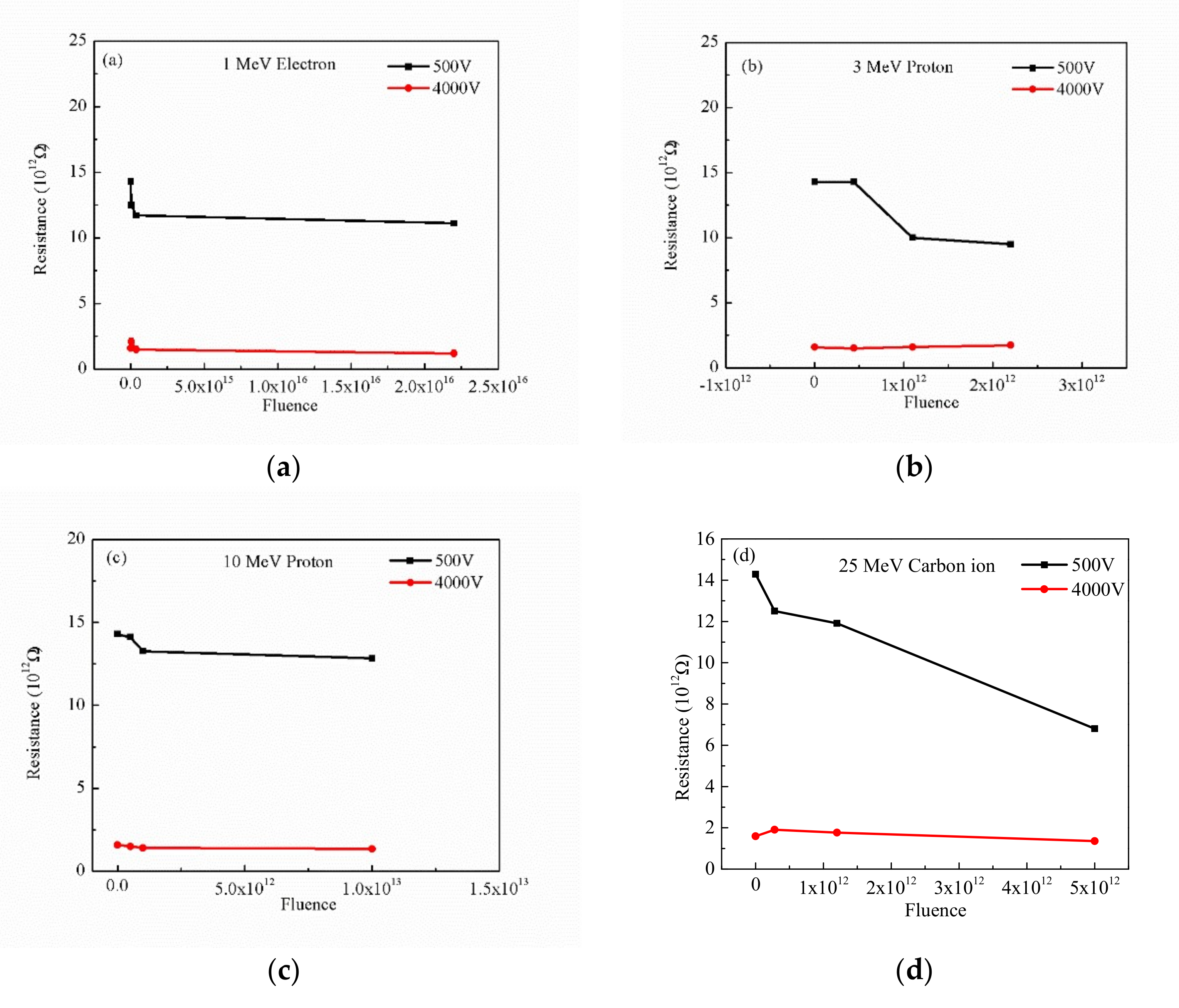
3.2. Dielectric Loss and Resistance Analysis
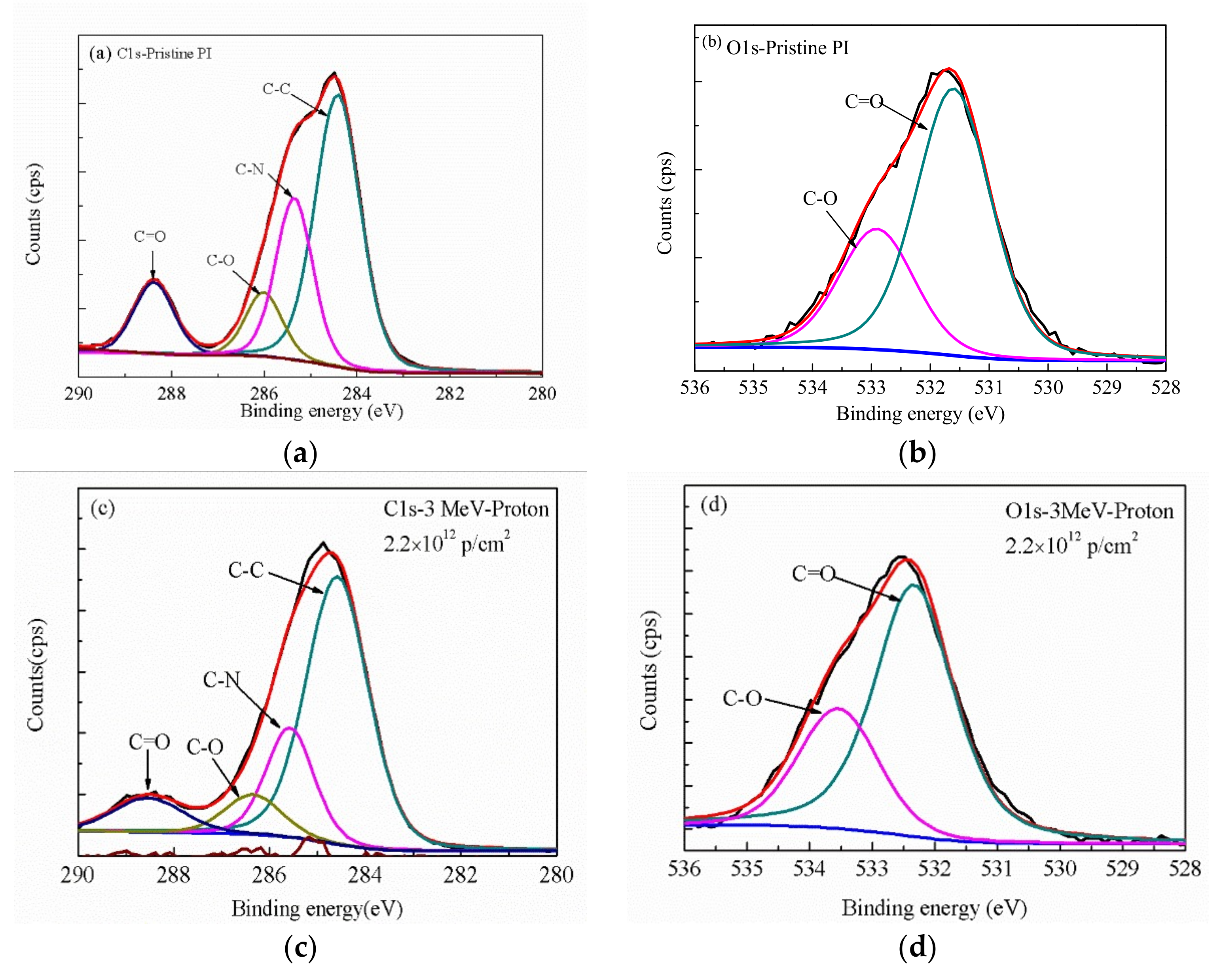
3.3. XPS Analysis
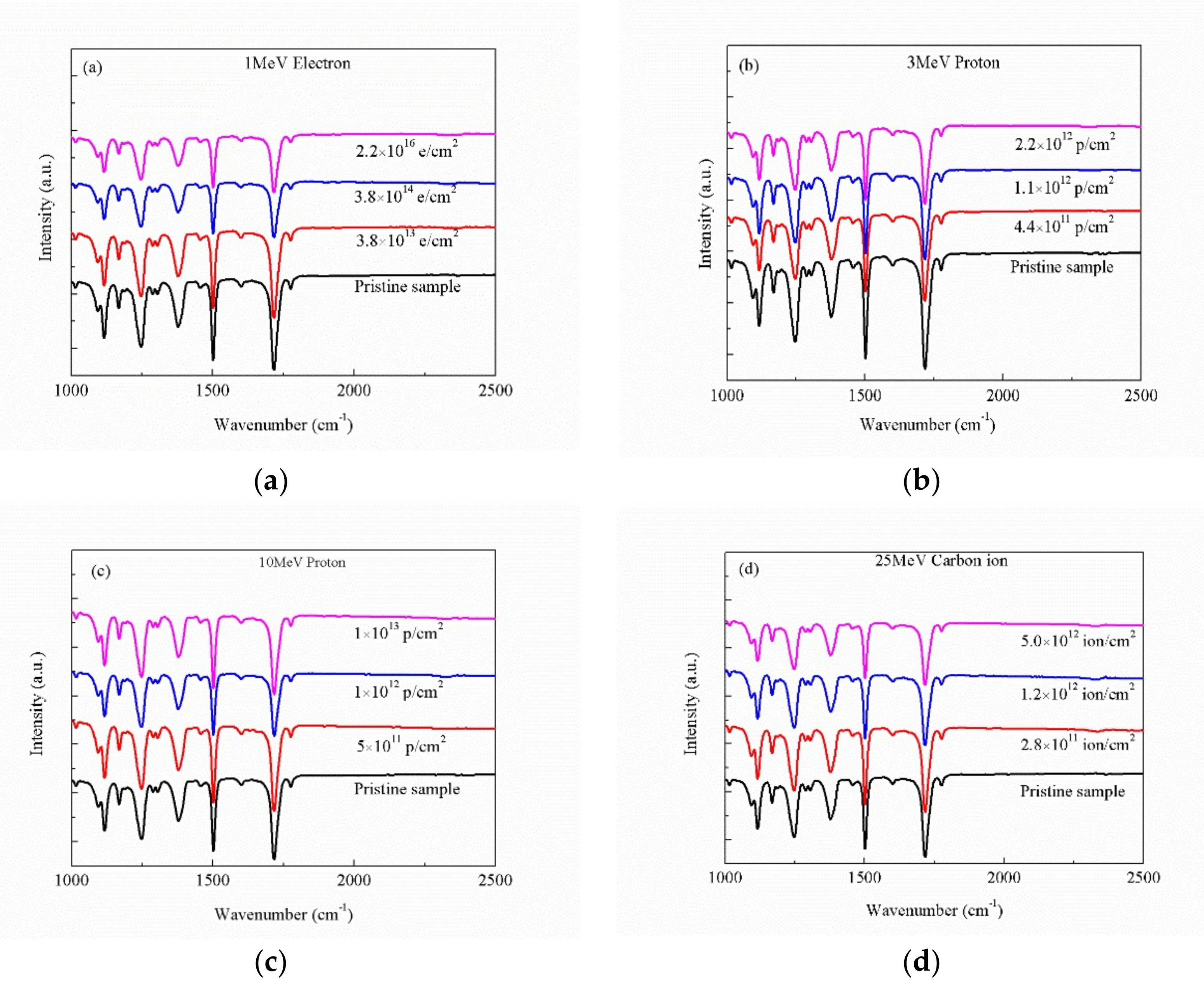
3.4. FT-IR Analysis
3.5. EPR Analysis
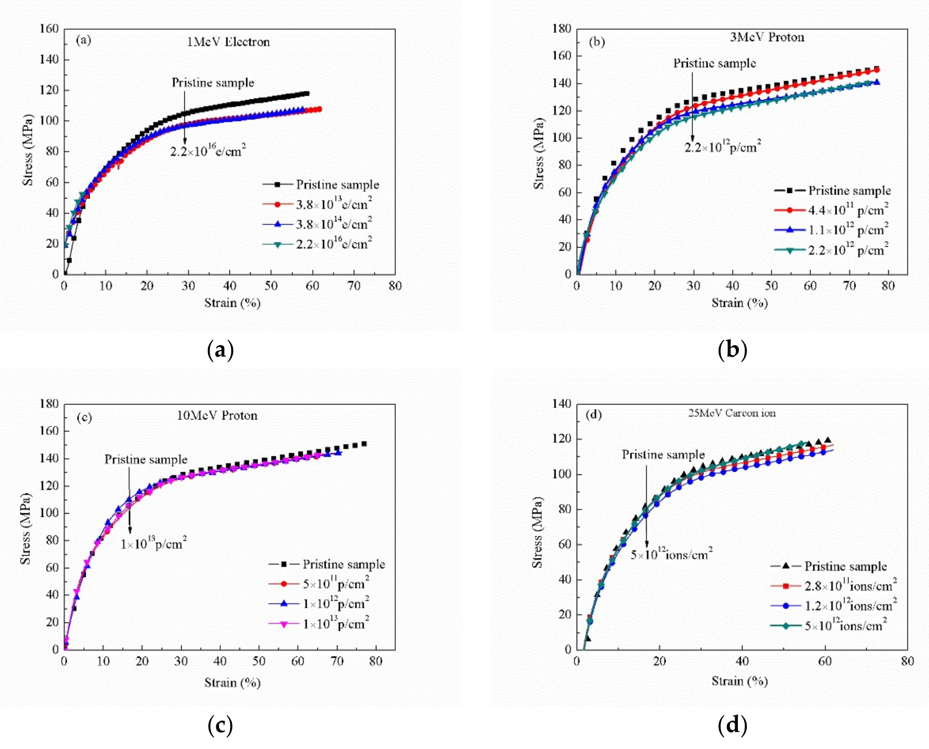
3.6. Mechanical Property Analysis
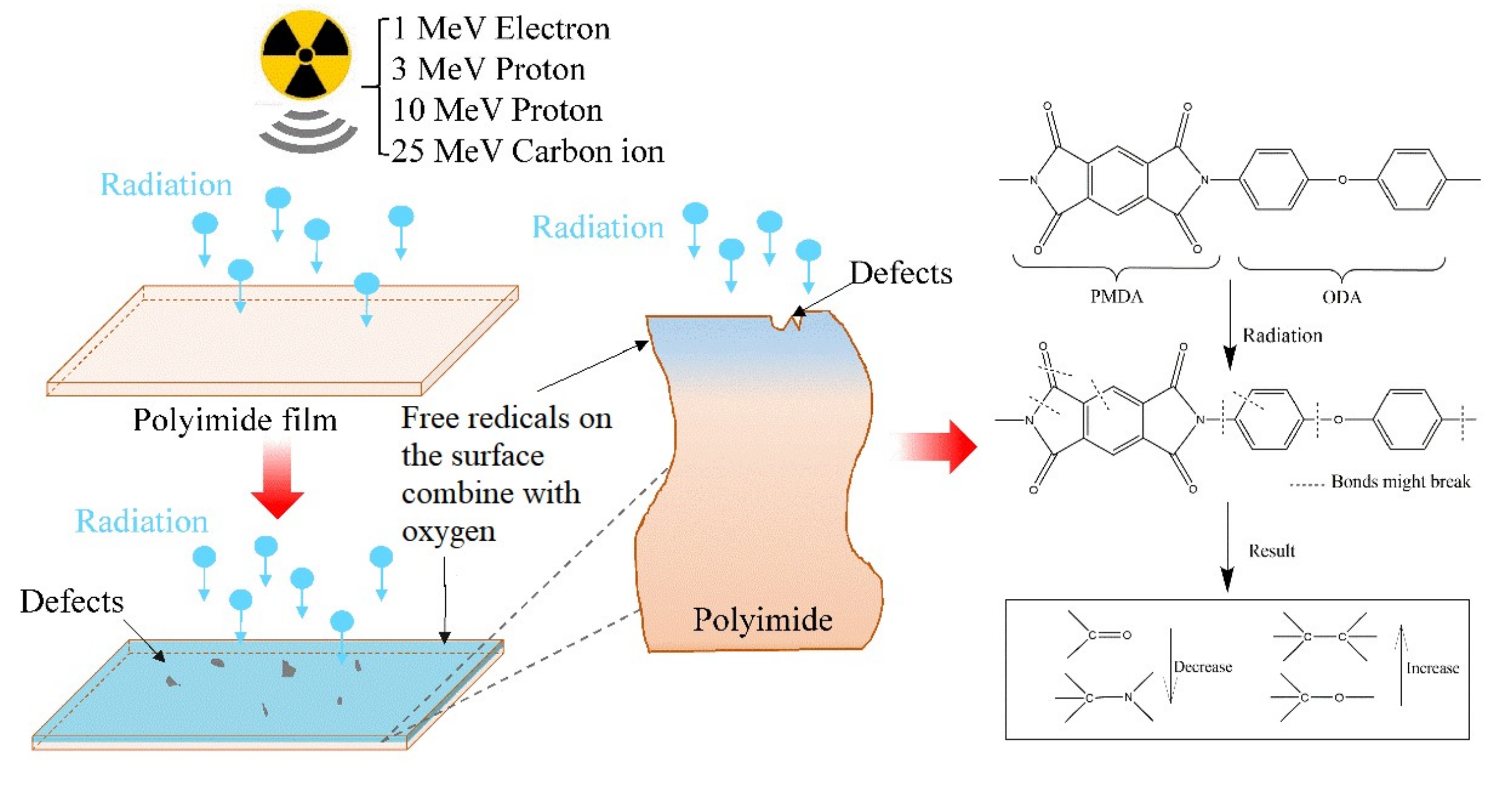
4. Discussion
5. Conclusions
Author Contributions
Funding
Conflicts of Interest
References
- Vesely, D.; Finch, D.S.; Cooley, G.E. Electrical properties of polymers modified by electron beam irradiation. Polymer 1988, 1402–1406. [Google Scholar] [CrossRef]
- Yawson, B.N.; Noh, Y. Recent Progress on High-capacitance polymer gate dielectrics for flexible low-voltage transistors. Adv. Funct. Mater. 2018, 28, 1802201. [Google Scholar]
- Constantinou, I.; Yi, X.; Shewmon, N.T.; Klump, E.D.; Peng, C.; Garakyaraghi, S.; Kin Lo, C.; Reynolds, J.R.; Castellano, F.N.; So, F. Effect of polymer-fullerene interaction on the dielectric properties of the blend. Adv. Energy Mater. 2017, 7, 1601947. [Google Scholar] [CrossRef]
- Wu, T.; Dong, J.; Gan, F.; Fang, Y.; Zhao, X.; Zhang, Q. Low dielectric constant and moisture-resistant polyimide aerogels containing trifluoromethyl pendent groups. Appl. Surf. Sci. 2018, 440, 595–605. [Google Scholar] [CrossRef]
- Yin, X.; Feng, Y.; Zhao, Q.; Li, Y.; Li, S.; Dong, H.; Hu, W.; Feng, W. Highly transparent, strong, and flexible fluorographene/fluorinated polyimide nanocomposite films with low dielectric constant. J. Mater. Chem. C 2018, 6, 6378. [Google Scholar] [CrossRef]
- Chen, X.; Huang, H.; Shu, X.; Liu, S.; Zhao, J. Preparation and properties of a novel graphene fluoroxide/polyimide nanocomposite film with a low dielectric constant. RSC Adv. 2017, 7, 1956–1965. [Google Scholar] [CrossRef] [Green Version]
- Lee, H.J.; Kim, J.; Kwon, O.; Lee, H.J.; Kwak, J.H.; Kim, J.M.; Lee, S.S.; Kim, Y.; Kim, D.-Y.; Jo, J.Y. Low coercive field of polymer ferroelectric via x-ray induced phase transition. Appl. Phys. Lett. 2015, 107, 262902. [Google Scholar] [CrossRef]
- Bonardd, S.; Alegria, A.; Saldias, C.; Leiva, A.; Kortaberria, G. Polyitaconates: A new family of “all-polymer” dielectrics. ACS Appl. Mater. Interfaces 2018, 10, 38476–38492. [Google Scholar] [CrossRef]
- Neese, B.; Chu, B.; Lu, S.; Wang, Y.; Furman, E.; Zhnag, Q.M. Large electrocaloric effect in ferroelectric polymers near room temperature. Science 2008, 3211, 821–823. [Google Scholar] [CrossRef]
- Ismaiilova, R.S.; Magerramov, A.M.; Kuliev, M.M.; Akhundova, G.A. Electrical conductivity and dielectric permittivity of γ-irradiated nanocomposites based on ultrahigh-molecular-weight polyethylene filled with α-SiO2. Surf. Eng. Appl. Electrochem. 2018, 54, 6–11. [Google Scholar] [CrossRef]
- Atta, A.; Lotfy, S.; Abdeltwab, E. Dielectric properties of irradiated polymer/multiwalled carbon nanotube and its amino functionalized form. J. Appl. Polym. Sci. 2018, 135, 46647. [Google Scholar]
- Jaschin, P.W.; Bhimireddi, R.; Varma, K.B.R. Enhanced dielectric properties of LaNiO3/BaTiO3/PVDF: A three-phase percolative polymer nanocrystal composite. ACS Appl. Mater. Interfaces 2018, 10, 27278–27286. [Google Scholar]
- Mackova, A.; Havra´nek, V.; Švorčík, V.; Djourelov, N.; Suzuki, T. Degradation of PET, PEEK and PI induced by irradiation with 150 keV Ar+ and 1.76 MeV He+ ions. Nuclear Instrum. Methods Phys. Res. B 2005, 240, 245–249. [Google Scholar]
- Ismail, N.H.; Mustapha, M.; Ismail, H.; Kamarol Jamil, M.; Hairaldin, S.C. Effect of Electron Beam Irradiation on Dielectric Properties, Morphology and Melt Rheology of Linear Low Density Polyethylene/Silicone Rubber-Based Thermoplastic Elastomer Nanocomposites. Polym. Eng. Sci. 2018, E135–E144. [Google Scholar]
- Abdelrahman, M.M.; Osman, M.; Hashhash, A. Electrical properties of irradiated PVA film by using ion/electron beam. Prog. Theor. Exp. Phys. 2016, 2016, 023G01. [Google Scholar]
- Mariania, M.; Ravasioa, U.; Varolia, V.; Consolati, G.; Faucitano, A.; Buttafava, A. Gamma irradiation of polyester films. Radiat. Phys. Chem. 2007, 76, 1385–1389. [Google Scholar]
- Raghu, S.; Kilarkaje, S.; Sanjeev, G.; Nagaraja, G.K.; Devendrappa, H. Effect of electron beam irradiation on polymer electrolytes: Change in morphology, crystallinity, dielectric constant and AC conductivity with dose. Radiat. Phys. Chem. 2014, 98, 124–131. [Google Scholar]
- Raghu, S.; Archana, K.; Sharanappa, C.; Ganesh, S.; Devendrappa, H. Electron beam and gamma ray irradiated polymer electrolyte films: Dielectric properties. J. Radiat. Res. Appl. Sci. 2016, 9, 117–124. [Google Scholar]
- Raghu, S.; Subramanya, K.; Sharanappa, C. The Change in Dielectric Constant, AC Conductivity and Optical Band Gaps of Polymer Electrolyte Film: Gamma Irradiation. Solid State Phys. AIP Conf. Proc. 2014, 1591, 1272–1274. [Google Scholar]
- Qureshi, A.; Singh, N.L.; Rakshit, A.K.; Singh, F.; Avasthi, D.K. Swift heavy ion induced modification in polyimide films. Surf. Coat. Technol. 2007, 201, 8308–8311. [Google Scholar]
- Quamara, J.; Garg, M.; Prabhavathi, T. Effect of high-energy heavy ion irradiation on dielectric relaxation behaviour of kapton-H polyimide. Thin Solid Films 2004, 449, 242–247. [Google Scholar] [CrossRef]
- Tkachenkoa, I.; Kononevichb, Y.; Kobzara, Y.; Purikova, O.; Yakovlev, Y.; Yakovlev, I.; Muzafarov, A.; Shevchenko, A. Low dielectric constant silica-containing cross-linked organic-inorganic materials based on fluorinated poly(arylene ether)s. Polymer 2018, 157, 131–138. [Google Scholar] [CrossRef]
- Dutta, N.J.; Mohanty, S.R.; Buzarbaruah, N.; Ranjan, M.; Rawat, R.S. Self-organized nanostructure formation on the graphite surface induced by helium ion irradiation. Phys. Lett. A 2018, 382, 1601–1608. [Google Scholar] [CrossRef]
- Naseem, S. Structural Optimization of SrMnO3 to Study Electro-Magnetic Characteristics. Master’s Thesis, University of the Punjab, Lahore, Pakistan. No. SSP-1308 Session 2013–2015.
- Yue, L.; Wu, Y.; Sun, C.; Xiao, J.; Shi, Y.; Ma, J.; He, S. Investigation on the radiation induced conductivity of space-applied polyimide under cyclic electron irradiation. Nucl. Instrum. Methods Phys. Res., Sect. B 2012, 291, 17–21. [Google Scholar] [CrossRef]


| Irradiation Energy | Fluence (cm−2) | Chemical Bond | Binding Energy (eV) | Proportion (%) |
|---|---|---|---|---|
| Pristine Polyimide | C–C | 284.5 | 60.4 | |
| C–N | 285.5 | 20.1 | ||
| C–O | 286.3 | 6.8 | ||
| C=O | 288.4 | 12.7 | ||
| 3 MeV Proton | 2.2 × 10¹² | C–C | 284.5 | 65.7 |
| C–N | 285.5 | 16.8 | ||
| C–O | 286.5 | 7.5 | ||
| C=O | 288.5 | 10.0 | ||
| 25 MeV Carbon ion 5.0 × 10¹² | C–C | 284.5 | 71.6 | |
| C–N | 285.5 | 11.4 | ||
| C–O | 286.5 | 7.3 | ||
| C=O | 288.5 | 9.7 | ||
| Irradiation Energy | Fluence (cm−2) | Chemical Bond | Binding Energy (eV) | Proportion (%) |
|---|---|---|---|---|
| Pristine Polyimide | C=O | 532 | 74.1 | |
| C–O | 533.2 | 25.9 | ||
| 3 MeV Proton | 2.2 × 10¹² | C=O | 532 | 71.1 |
| C–O | 533.2 | 28.9 | ||
| 25 MeV Carbon ion | 5.0 × 10¹² | C=O | 532 | 70.6 |
| C–O | 533.2 | 29.4 | ||
| Bond | α// | αꞱ | αm |
|---|---|---|---|
| C–N | 0.58 | 0.84 | 0.75 |
| C–H | 0.79 | 0.58 | 0.65 |
| C–C | 1.88 | 0.02 | 0.64 |
| C–O | 2.25 | 0.48 | 1.07 |
| C=O | 2.00 | 0.75 | 1.20 |
| Bond | μ (10−30/CM) |
|---|---|
| C–N | 0.40 |
| C–H | 0.74 |
| C–C | 0.00 |
| C–O | 2.30 |
| C=O | 0.73 |
© 2020 by the authors. Licensee MDPI, Basel, Switzerland. This article is an open access article distributed under the terms and conditions of the Creative Commons Attribution (CC BY) license (http://creativecommons.org/licenses/by/4.0/).
Share and Cite
Li, H.; Yang, J.; Dong, S.; Tian, F.; Li, X. Low Dielectric Constant Polyimide Obtained by Four Kinds of Irradiation Sources. Polymers 2020, 12, 879. https://doi.org/10.3390/polym12040879
Li H, Yang J, Dong S, Tian F, Li X. Low Dielectric Constant Polyimide Obtained by Four Kinds of Irradiation Sources. Polymers. 2020; 12(4):879. https://doi.org/10.3390/polym12040879
Chicago/Turabian StyleLi, Hongxia, Jianqun Yang, Shangli Dong, Feng Tian, and Xingji Li. 2020. "Low Dielectric Constant Polyimide Obtained by Four Kinds of Irradiation Sources" Polymers 12, no. 4: 879. https://doi.org/10.3390/polym12040879