
3D Printing of Customized Aspheric Lenses for Imaging

Abstract
:
1. Introduction
2. Materials and Methods
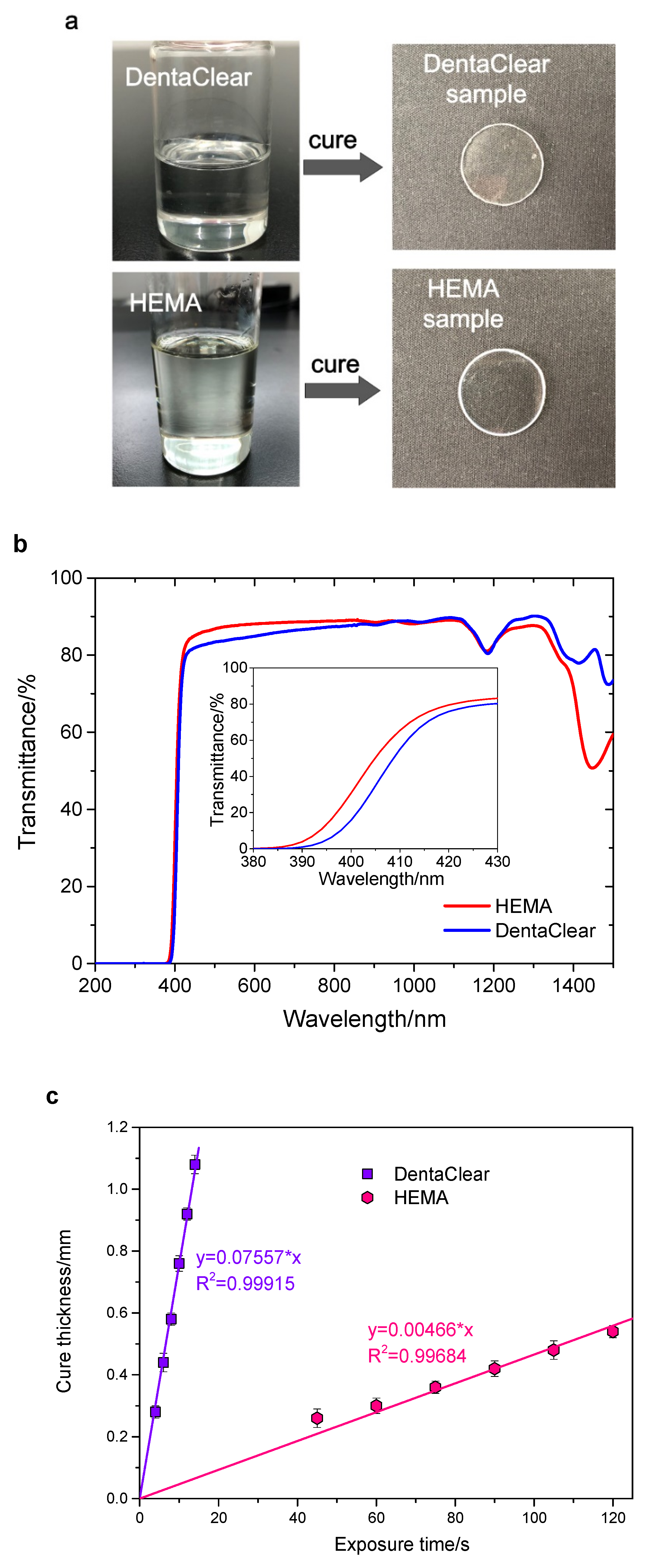
2.1. Preparation of UV-Curable Resins
2.2. Aspheric Lens Design
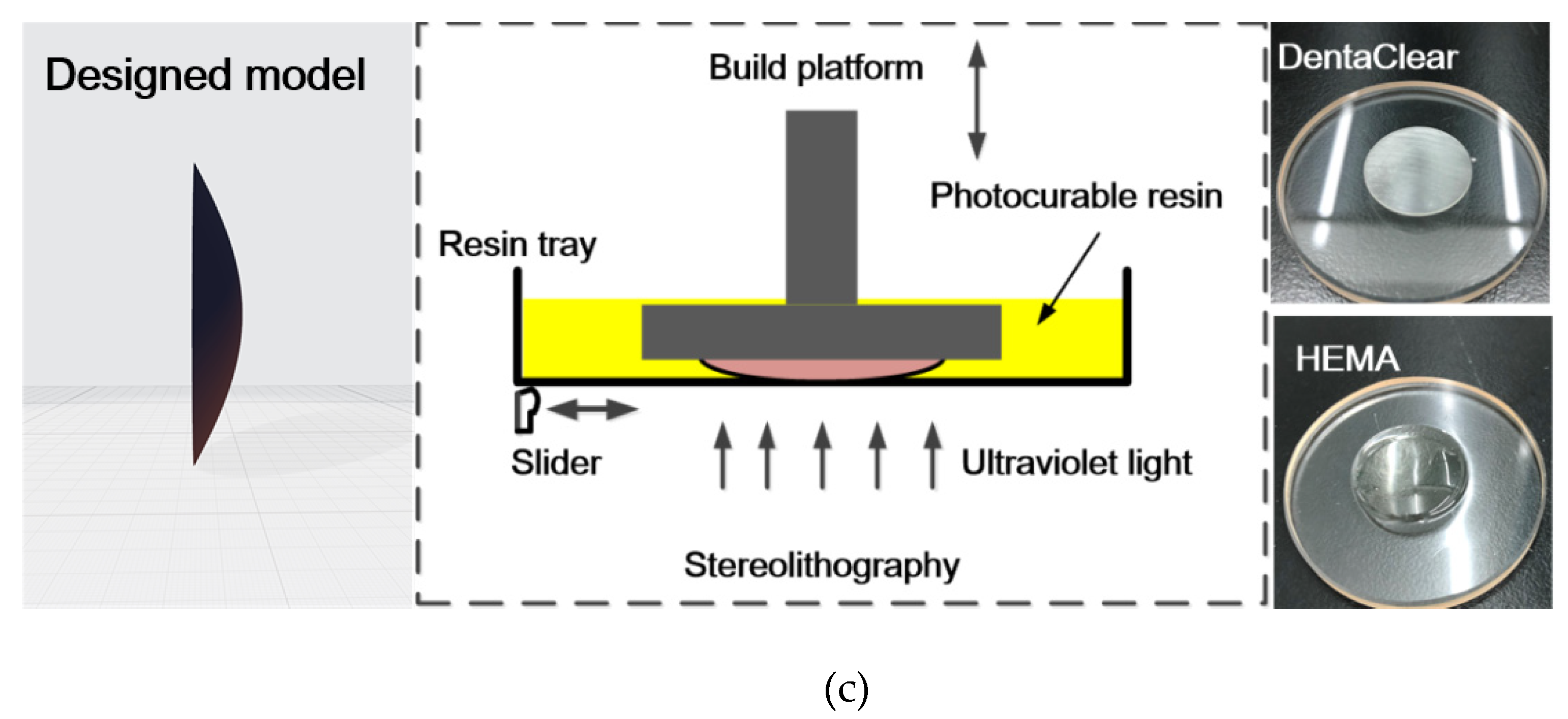
2.3. Stereolithography Fabrication and Meniscus Equilibrium Post-Curing of Aspheric Lenses
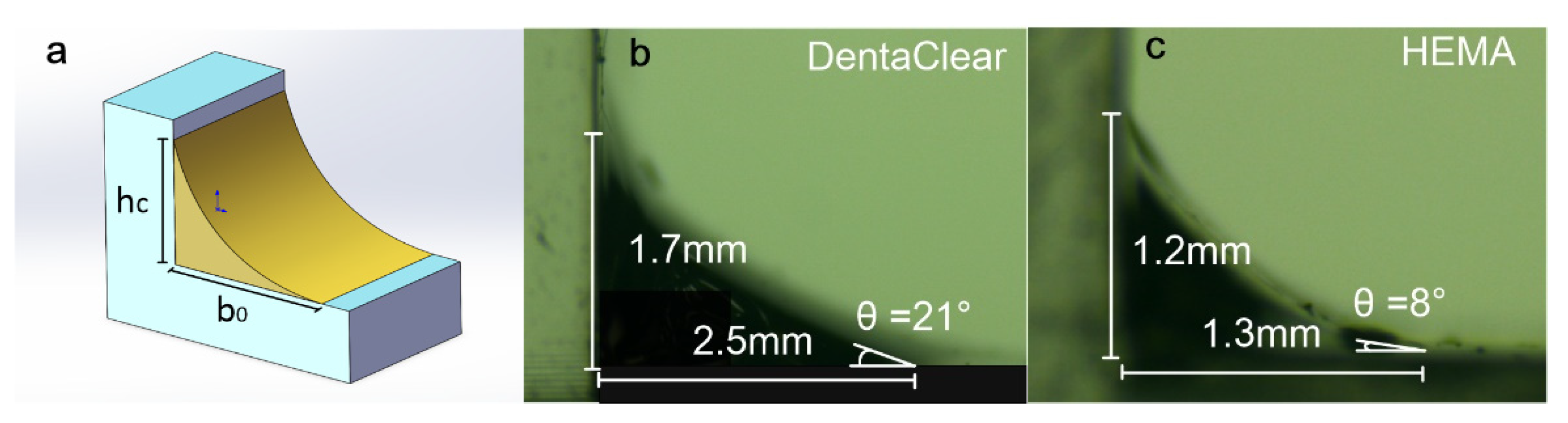
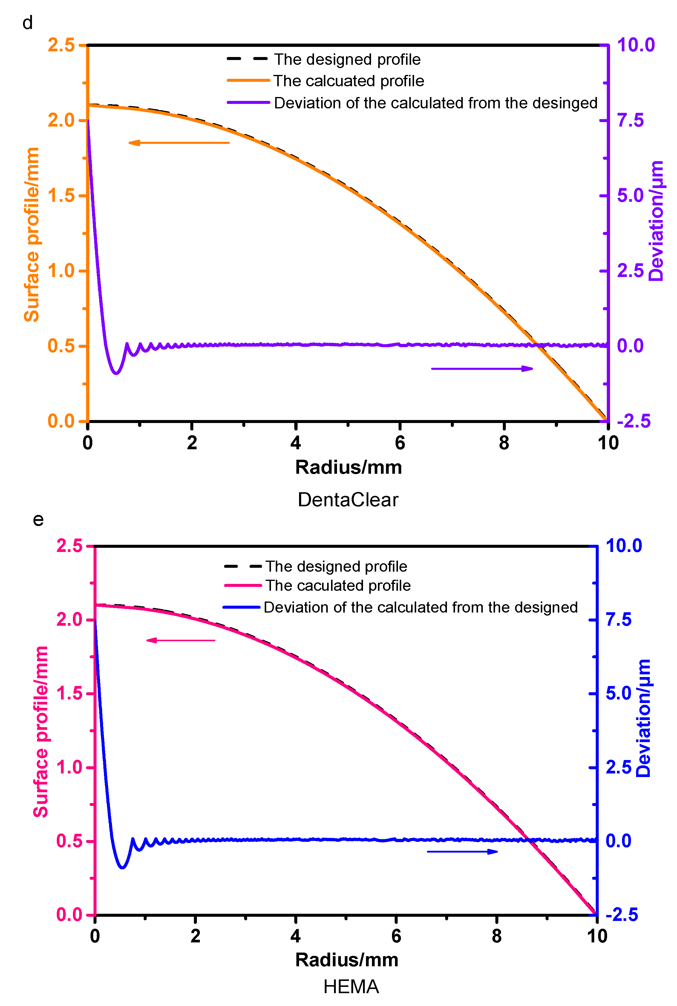
3. Simulation of the Meniscus Equilibrium Post-Curing Process
4. Results and Discussion
4.1. Surface Characterization of the Printed Lenses
4.2. Imaging Performance
5. Conclusions
Author Contributions
Funding
Institutional Review Board Statement
Informed Consent Statement
Data Availability Statement
Conflicts of Interest
References
- Fattoum, E.Y.; Al-Khateb, E.Y.; Katnah, A.; Jabra, R. Design, manufacturing and measurement of aspheric test-plate using only traditional techniques. J. Opt. 2017, 46, 287–294. [Google Scholar] [CrossRef]
- Chen, X.; Liu, W.; Dong, B.; Lee, J.; Ware, H.O.T.; Zhang, H.F.; Sun, C. High-speed 3D printing of millimeter-size customized aspheric imaging lenses with sub 7 nm surface roughness. Adv. Mater. 2018, 30, 1705683. [Google Scholar] [CrossRef]
- Thiele, S.; Arzenbacher, K.; Gissibl, T.; Giessen, H.; Herkommer, A.M. 3D-printed eagle eye: Compound microlens system for foveated imaging. Sci. Adv. 2017, 3, e1602655. [Google Scholar] [CrossRef] [Green Version]
- Van Lith, R.; Baker, E.; Ware, H.; Yang, J.; Farsheed, A.C.; Sun, C.; Ameer, G. 3D-printing strong high-resolution antioxidant bioresorbable vascular stents. Adv. Mater. Technol. 2016, 1, 1600138. [Google Scholar] [CrossRef]
- Kotz, F.; Risch, P.; Helmer, D.; Rapp, B.E. Highly fluorinated methacrylates for optical 3D printing of microfluidic devices. Micromachines 2018, 9, 115. [Google Scholar] [CrossRef] [PubMed] [Green Version]
- Eckel, Z.C.; Zhou, C.; Martin, J.H.; Jacobsen, A.J.; Carter, W.B.; Schaedler, T.A. Additive manufacturing of polymer-derived ceramics. Science 2016, 351, 58–62. [Google Scholar] [CrossRef] [PubMed] [Green Version]
- Surdo, S.; Carzino, R.; Diaspro, A.; Duocastella, M. Single-Shot Laser Additive Manufacturing of High Fill-Factor Microlens Arrays. Adv. Opt. Mater. 2018, 6, 1701190. [Google Scholar] [CrossRef]
- Xing, J.; Rong, W.; Sun, D.; Wang, L.; Sun, L. Extrusion printing for fabrication of spherical and cylindrical microlens arrays. Appl. Opt. 2016, 55, 6947–6952. [Google Scholar] [CrossRef] [PubMed]
- Gissibl, T.; Thiele, S.; Herkommer, A.; Giessen, H. Two-photon direct laser writing of ultracompact multi-lens objectives. Nat. Photonics 2016, 10, 554–560. [Google Scholar] [CrossRef]
- Assefa, B.G.; Saastamoinen, T.; Biskop, J.; Kuittinen, M.; Turunen, J.; Saarinen, J. 3D printed plano-freeform optics for non-coherent discontinuous beam shaping. Opt. Rev. 2018, 25, 456–462. [Google Scholar] [CrossRef]
- Shao, G.; Hai, R.; Sun, C. 3D printing customized optical lens in minutes. Adv. Opt. Mater. 2020, 8, 1901646. [Google Scholar] [CrossRef]
- Assefa, B.G.; Pekkarinen, M.; Partanen, H.; Biskop, J.; Turunen, J.; Saarinen, J. Imaging-quality 3D-printed centimeter-scale lens. Opt. Express 2019, 27, 12630–12637. [Google Scholar] [CrossRef] [PubMed]
- Melchels, F.P.W.; Feijen, J.; Grijpma, D.W. A review on stereolithography and its applications in biomedical engineering. Biomaterials 2010, 31, 6121–6130. [Google Scholar] [CrossRef] [Green Version]
- Berglund, G.D.; Tkaczyk, T.S. Fabrication of optical components using a consumer-grade lithographic printer. Opt. Express 2019, 27, 30405–30420. [Google Scholar] [CrossRef]
- Vaidya, N.; Solgaard, O. 3D printed optics with nanometer scale surface roughness. Microsyst. Nanoeng. 2018, 4, 18. [Google Scholar] [CrossRef]
- Pan, Y.; Zhao, X.; Zhou, C.; Chen, Y. Smooth surface fabrication in mask projection based stereolithography. J. Manuf. Process. 2012, 14, 460–470. [Google Scholar] [CrossRef]
- Pan, Y.; Chen, Y. Meniscus process optimization for smooth surface fabrication in Stereolithography. Addit. Manuf. 2016, 12, 321–333. [Google Scholar] [CrossRef]
- Pan, Y.; Chen, Y. Smooth surface fabrication based on controlled meniscus and cure depth in microstereolithography. J. Micro Nano-Manuf. 2015, 3, 031001. [Google Scholar] [CrossRef]
- Raman, R.; Bhaduri, B.; Mir, M.; Shkumatov, A.; Lee, M.K.; Popescu, G.; Kong, H.; Bashir, R. High-resolution projection microstereolithography for patterning of neovasculature. Adv. Healthcare Mater. 2016, 5, 610–619. [Google Scholar] [CrossRef]
- Zmarzły, P.; Gogolewski, D.; Kozior, T. Design guidelines for plastic casting using 3D printing. J. Eng. Fibers Fabr. 2020, 15, 1558925020916037. [Google Scholar] [CrossRef]
- Kotz, F.; Arnold, K.; Bauer, W.; Schild, D.; Keller, N.; Sachsenheimer, K.; Nargang, T.M.; Richter, C.; Helmer, D.; Rapp, B.E. Three-dimensional printing of transparent fused silica glass. Nature 2017, 544, 337–339. [Google Scholar] [CrossRef] [PubMed]
- Moore, D.G.; Barbera, L.; Masania, K.; Studart, A.R. Three-dimensional printing of multicomponent glasses using phase-separating resins. Nat. Mater. 2020, 19, 212–217. [Google Scholar] [CrossRef] [PubMed]


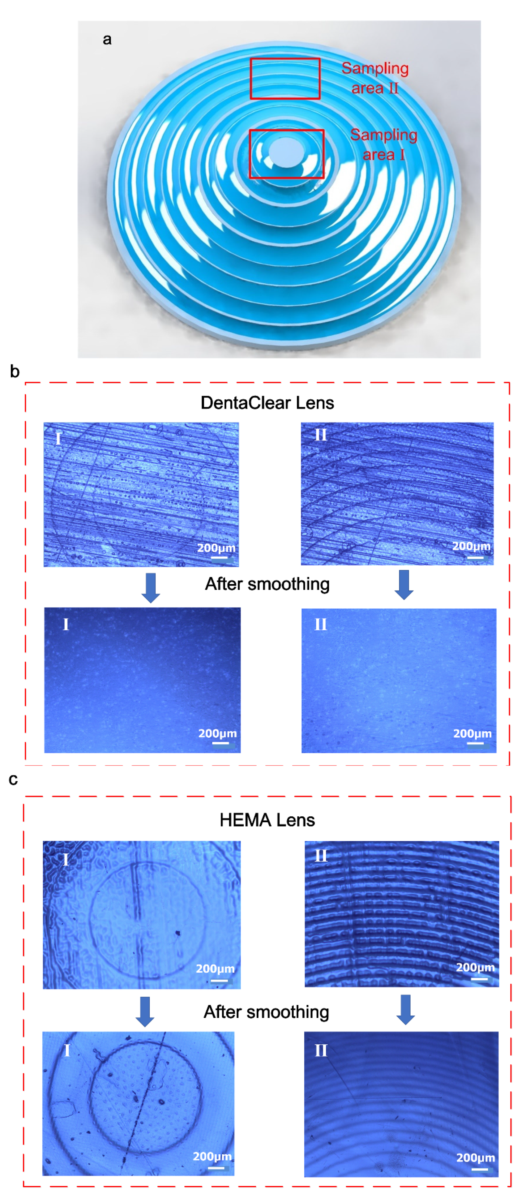
| DentaClear lens | HEMA lens | |||||
|---|---|---|---|---|---|---|
| Stair-Stepping Effect | Surface Roughness Measured by Profile Meter | Deviation from Designed Profile | Stair-Stepping Effect | Surface Roughness Measured by Profile Meter | Deviation from Designed Profile | |
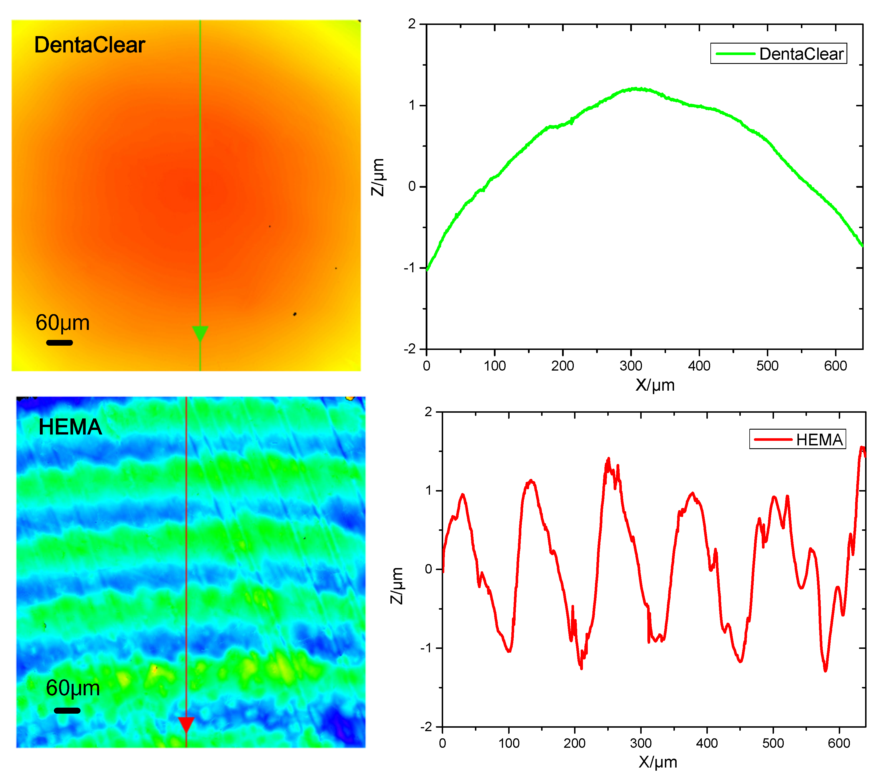
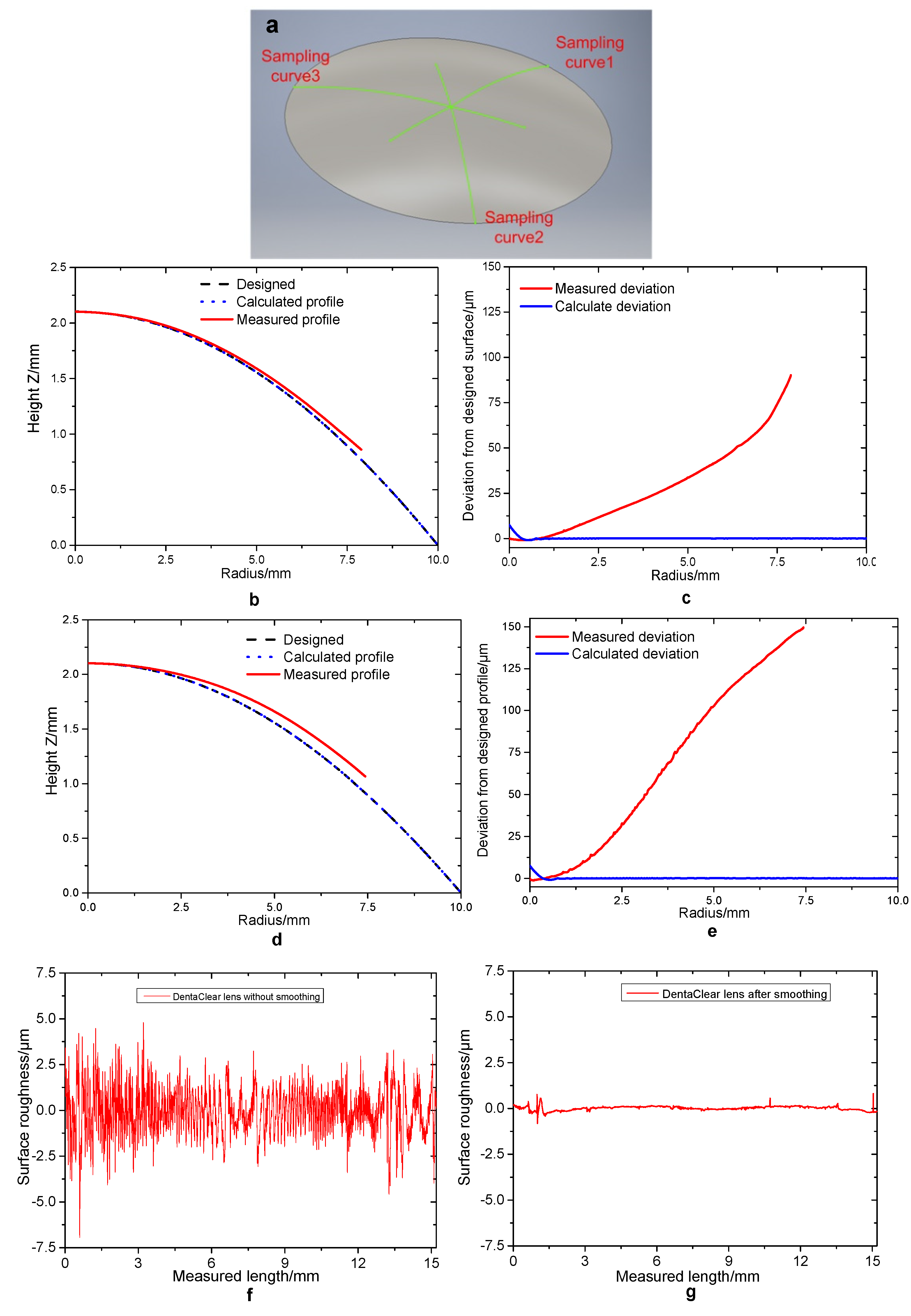
| Before smoothing | visible | 1.34 | N/A | visible | 0.93 | N/A |
| After smoothing | invisible | 0.16 | ~74 at 7.5 mm | visible | 0.43 | ~150 at 7.5 mm |
| Surface Properties | Image Resolution | |||
|---|---|---|---|---|
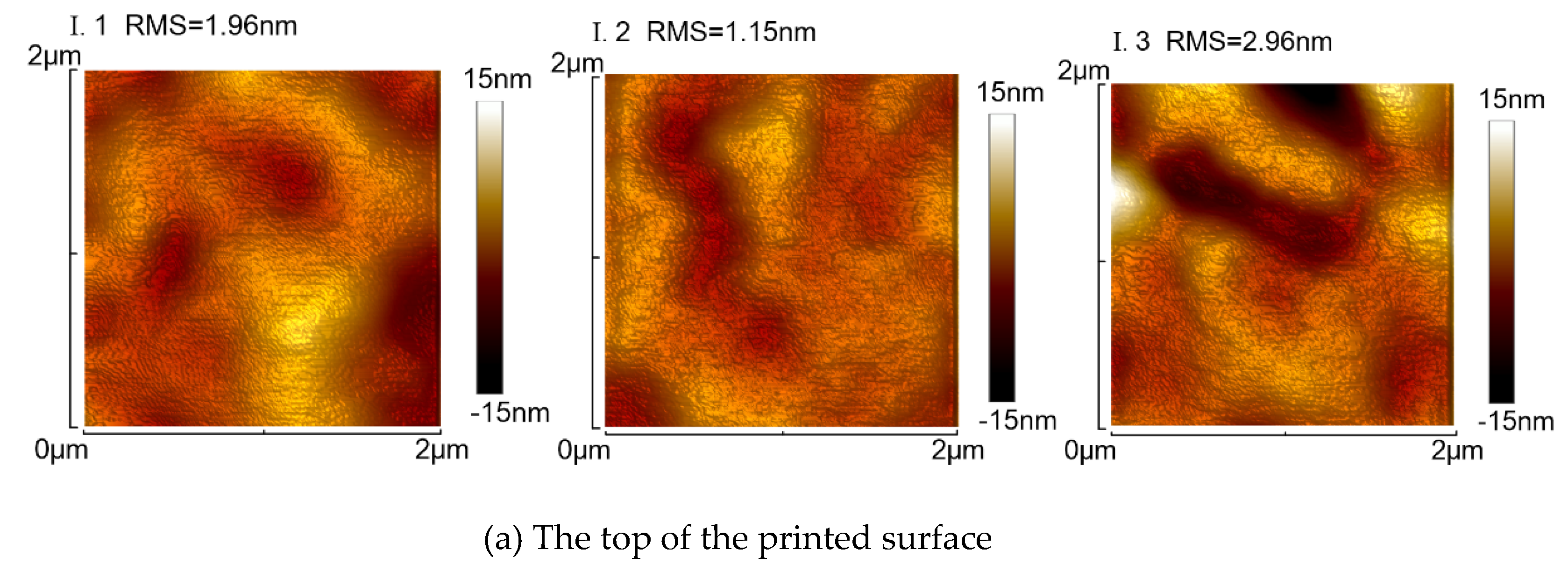
| Surface Roughness Measured by Stylus Profilometry | Surface Roughness Measured by AFM | White Light | Green Light | |
| DentaClear lens | 0.16 | 2.02 nm | 8.77 | 4.92 |
| HEMA lens | 0.43 | N/A | N/A | N/A |
Publisher’s Note: MDPI stays neutral with regard to jurisdictional claims in published maps and institutional affiliations. |
© 2021 by the authors. Licensee MDPI, Basel, Switzerland. This article is an open access article distributed under the terms and conditions of the Creative Commons Attribution (CC BY) license (https://creativecommons.org/licenses/by/4.0/).
Share and Cite
Zhu, D.; Zhang, J.; Xu, Q.; Li, Y. 3D Printing of Customized Aspheric Lenses for Imaging. Polymers 2021, 13, 3477. https://doi.org/10.3390/polym13203477
Zhu D, Zhang J, Xu Q, Li Y. 3D Printing of Customized Aspheric Lenses for Imaging. Polymers. 2021; 13(20):3477. https://doi.org/10.3390/polym13203477
Chicago/Turabian StyleZhu, Dexing, Jian Zhang, Qiao Xu, and Yaguo Li. 2021. "3D Printing of Customized Aspheric Lenses for Imaging" Polymers 13, no. 20: 3477. https://doi.org/10.3390/polym13203477
APA StyleZhu, D., Zhang, J., Xu, Q., & Li, Y. (2021). 3D Printing of Customized Aspheric Lenses for Imaging. Polymers, 13(20), 3477. https://doi.org/10.3390/polym13203477