Abstract
Additive manufacturing (3D printing) has significantly changed the prototyping process in terms of technology, construction, materials, and their multiphysical properties. Among the most popular 3D printing techniques is vat photopolymerization, in which ultraviolet (UV) light is deployed to form chains between molecules of liquid light-curable resin, crosslink them, and as a result, solidify the resin. In this manuscript, three photopolymerization technologies, namely, stereolithography (SLA), digital light processing (DLP), and continuous digital light processing (CDLP), are reviewed. Additionally, the after-cured mechanical properties of light-curable resin materials are listed, along with a number of case studies showing their applications in practice. The manuscript aims at providing an overview and future trend of the photopolymerization technology to inspire the readers to engage in further research in this field, especially regarding developing new materials and mathematical models for microrods and bionic structures.
1. Introduction
Additive manufacturing (AM) technology was first introduced in the 1980s with the aim of producing rapid and functional prototypes from various materials. Particularly, in May 1980, Dr. Hideo Kodama from the Nagoya Municipal Industrial Research Institute (NMIRI) applied for a patent that describes a method of curing a spatial model of photopolymer material by exposing it to ultraviolet (UV) light. Nevertheless, Kodama’s efforts toward finding funding for further research and development on the issued patent bore no fruit, even with support from the government. The patent was consequently abandoned and never commercialized [1,2,3,4]. Kodama is, however, credited as the first inventor of this technology.
The origin of 3D printing with commercial potential can be traced back to 1986 when Charles W. Hull filed a patent for a photopolymerization technology called stereolithography (SLA). The very first printed model was an eye-wash cup. Henceforth, SLA has been developed by 3D Systems Corporation [1,2,3].
New developments are also closely related to the development of 3D printing in medical and regenerative medicine. Dating back to 2004 in [5], a novel technique for printing 3D cell patterns was introduced. Later on, in [6], the author describes the process of manufacturing structures, namely, scaffolds, on which, cells can grow after being implemented into the body. A typical example of 3D bioprinting is artificial vessels, for which, dog bone marrow samples were used [7,8].
2. Vat Photopolymerization
AM technologies are classified as shown below in Figure 1. Each technology differs from another in the manner of the application process, curing principle, and the initial state of the material. Herein, attention is paid to the historically oldest AM technology, namely, vat photopolymerization.
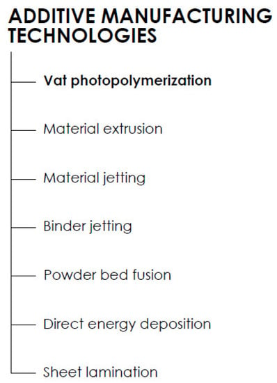
Figure 1.
Division of the additive manufacturing (AM) technologies according to ISO/ASTM 52900: 2015 Additive Manufacturing—General Principles—Terminology.
2.1. 3D Printing Process
The 3D printing production process begins with a 3D model that is designed with computer-aided design (CAD) software or 3D scanned from a physical object. The 3D model is subsequently converted to the standard triangulation language (STL) format. It should be noted that since 1987, STL has been the standard and most frequently used format for preparing data for AM production. Specifically, the STL format solely describes the surface of the 3D model with a network of triangles of different sizes, depending on the required resolution. The smaller the size of the triangles, the more accurately the triangular mesh represents the desired surface, yielding a smoother surface of the to-be-printed object. The stage in which preparing the desired mesh model takes place is called preprocessing [9].
The second production stage is called processing. As a 3D printed object is fabricated layer by layer, each consecutive layer has to be supported by either the platform, the preceding layer, or extra support elements. After designing the correct and optimal orientation of the model and the supports, the STL model, including the supports, is sliced into layers with a plane parallel to the platform surface, namely, the xOy plane. Each layer is then built consecutively in the Oz direction. The layer thickness depends on the printer, AM technology, and quality requirements. The sliced model is subsequently sent to the printer. Differing from the traditional subtractive manufacturing process (machining), where the material is taken out of a workpiece, AM offers more efficient material usage.
After the printing is finished, the model is removed from the platform and other technical processing procedures are used to refine the printed object in a stage called postprocessing. In the case of photopolymerization, the as-built models are rinsed in a wash solution, most commonly, isopropyl alcohol (IPA), to get rid of the liquid layer of resin. To enhance the mechanical properties, these models are subsequently artificially cured with UV light or naturally exposed to sunlight. Other processes include support removal, grinding, sealing, gluing, polishing, painting, varnishing, coating, sterilization, inspection, and measurement. There are specific post-processing treatments for photopolymer parts. It is noteworthy that the rinsing time, temperature, and duration of the curing process play an important role in determining the mechanical properties of the finished parts.
A typical printing process with SLA technology is shown below in Figure 2.
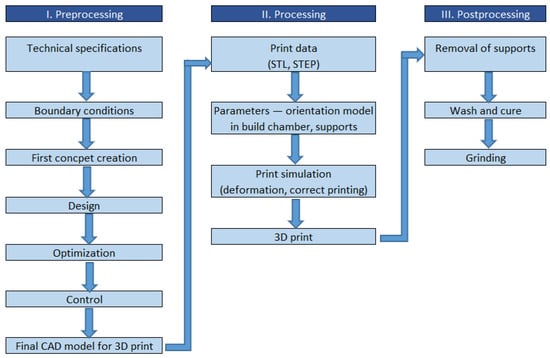
Figure 2.
A typical production process with photopolymerization. CAD: computer-aided design, STL: standard triangulation language, STEP: standard for the exchange of product data.
2.2. Printing Principle of Photopolymerization
In the photopolymerization process, a photopolymer, which is a light-curable resin, is stored in a vat and treated with either visible or UV light. The curing light triggers and manifests the polymerization reaction, which then forms chains of polymers or crosslinks them to form a solid resin. As can be seen in Figure 3, three elements of the photopolymer mixture are monomers, oligomers, and photoinitiators. When exposed to curing light, photoinitiators release creative species that work as catalysts for the chain formation among monomers and oligomers. The chain-forming chemical-thermal process is irreversible and prototypes cannot be changed back to liquid form. Utilizing this principle, consecutive layers of resin are fabricated gradually from a sliced STL file [10,11,12,13,14].

Figure 3.
Liquid photopolymer (on the left), induced polymerization by light (small circle—monomer, large circle—oligomer, star—photoinitiator).
Photopolymerization is classified with regard to the method of curing (Figure 4), which employ lasers (SLA), digital projection (digital light processing (DLP)), and light-emitting diodes (LEDs) and oxygen (continuous digital light processing (CDLP)/continuous liquid interface production (CLIP)) [9,15,16,17,18,19].
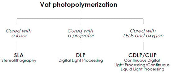
Figure 4.
Different curing methods for vat photopolymerization. LEDs: light-emitting diodes.
2.3. Classification
2.3.1. Stereolithography
A 3D printer with SLA technology uses a platform immersed in a transparent tank that is filled with light-curable resin (henceforth, simply resin). While the platform is immersed in the resin, the laser beam traces the construction area and cures the areas according to the sliced STL template. After a layer is formed, the platform is lowered or raised in the Oz direction, depending on whether the machine uses a top-down or bottom-up process, by a constant amount equaling the height of a layer. The curing process is repeated layer-by-layer until a 3D model is completed. The height of a layer ranges from 12 to 150 µm. In practice, 100 µm is the most chosen layer height. The print speed of standard SLA printers is in the range of 10–20 mm/h. The principle of a 3D printer with SLA technology is shown in Figure 5. The accuracy of SLA production is related to the diameter of the laser beam at the curing point, namely, the spot size. For example, for a Formlabs Form 2 SLA, the spot size is 140 µm [18,19].
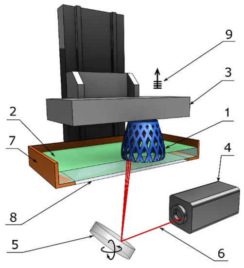
Figure 5.
Components of a typical SLA machine: 1—printed part, 2—liquid resin, 3—building platform, 4—UV laser source, 5—XY scanning mirror, 6—laser beam, 7—resin tank, 8—window, and 9—layer-by-layer elevation.
2.3.2. Digital Light Processing
DLP technology differs from SLA solely in the curing method. Instead of a mirror to reflect a laser source, a digital light projector is employed. In comparison with SLA technology, the DLP process is faster as each layer is entirely exposed to the curing light projected from the digital screen. Since DLP technology utilizes a digital light projector, each layer appears pixelized and the accuracy of the printed part depends greatly on the projector resolution. A typical DLP machine and its components are illustrated below in Figure 6 [18].
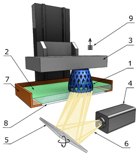
Figure 6.
Components of a typical DLP machine: 1—printed part, 2—liquid resin, 3—building platform, 4—light source, 5—digital projector, 6—light beam, 7—resin tank, 8—window, and 9—layer-by-layer elevation.
2.3.3. Continuous Digital Light Processing/Continuous Liquid Interface Production
CDLP/CLIP technology is an innovation based on DLP technology [16]. In particular, being different from SLA and DLP technology, CDLP/CLIP employs digital projection with LEDs and an oxygen-permeable window instead of a normal glass window. This oxygen-permeable window forms a so-called dead zone as thick as a human hair, which allows the liquid resin to flow between the interface of the printed part and the window. This uncured resin flow remarkably increases the resolution of the printed part, as well as decreasing the risk of printing failure due to the peeling force. Moreover, as opposed to the layer-by-layer method, CDLP/CLIP machines are designed with continuous movement of the build platform, thus, allowing for undisrupted prototype printing at speeds of several hundred millimeters per hour [15,16,18]. A typical CDLP/CLIP machine and its components are illustrated below in Figure 7.
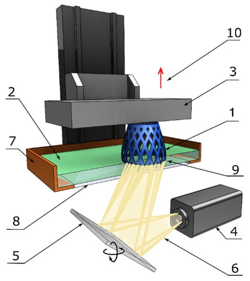
Figure 7.
Components of a typical CDLP/CLIP machine: 1—printed part, 2—liquid resin, 3—building platform, 4—light source, 5—digital projector, 6—light beam, 7—resin tank, 8—oxygen-permeable window, 9—dead zone, and 10—continuous elevation.
Thanks to the continuous printing process, the problem regarding layer connection is eliminated and the visible staircase effect is minimized. Therefore, the fabricated parts have isotropic mechanical properties, although they may appear anisotropic [20,21]. This technology was utilized to 3D print supramolecular hydrogels, as seen in [17,18].
2.3.4. Two-Photon Lithography (2PL)
2PL is a direct laser-writing (DLW) method that uses a laser beam to create 3D microstructures with a resolution below the diffraction limit. This is possible thanks to the polymerization of a photosensitive polymeric material, namely, a (photo)resist, based on the two-photon absorption (2PA) principle [22]. This technology has found its place in medical applications thanks to the ability to produce solid polymer objects, whose resolution is several nanometers. Unlike traditional 3D printing, 2PL technology can freely cure solid polymer in the resin vat, eliminating the need for material deposition in a layer-by-layer manner. Subsequently, the printed parts are treated in a suitable solvent to remove the uncured liquid resin. The smallest polymer identity in 3D printing with 2PL is an ellipsoidal 3D point, which is known as a voxel (volume pixel) [22]. It should be noted that the printing principle described above is applicable to negative photoresists, whose uncured portion dissolves in the solvent during postprocessing, while the cured portion does not.
The absorption coefficient of two photons in 2PL is defined by the equation:
where ℏ is the Dirac constant, ω is the laser frequency, I is the irradiance or power (radiation flux) per focused volume, v is the rate of transition of 2PA to the voxel, N is the density of the photoresist (number of reaction molecules in the voxel), E is the photon energy, σ is the cross-section of the 2PA (cm4·s/photon). This equation was taken from [23].
2.4. Accuracy
2.4.1. Accuracy Comparison between SLA, DLP, and CDLP/CLIP
The curing light source and the light-projecting method play key roles in determining the accuracy of the printed parts. As for SLA, the footprint of the curing laser beam on the xOy plane is a spot and the accuracy depends on the spot diameter, whereas in DLP and CDLP/CLIP, the accuracy is given by the pixel matrix, which is defined by the resolution of the digital projector. In contrast to the flexibility that SLA offers, thanks to the free movement of the laser beam, DLP and CDLP/CLIP are limited to the network of pixels of the digital screen, which is illuminated wholly one at a time for each layer. As a result, the DLP and CDLP/CLIP deliver less accurate, Minecraft-like parts in comparison with SLA, despite its many-fold smaller individual footprint. A comparison of the production accuracies is illustrated in Figure 8 below, where a scan track in SLA is approximated with voxels in DLP and CDLP/CLIP. With regard to this fact, it can be stated that SLA technology can deliver higher accuracy than DLP and CDLP/CLIP at a cost of production time. Additionally, as aforementioned, CDLP/CLIP can fabricate parts with better accuracy and mechanical properties in comparison with DLP thanks to the continuous movement of the platform and the existence of the dead zone.
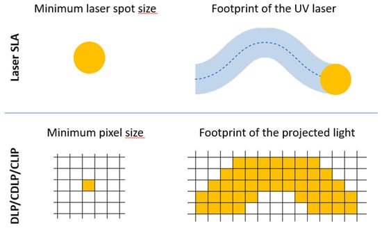
Figure 8.
Accuracy comparison between SLA and DLP/CDLP/CLIP based on their footprint on building platform, namely, the xOy plane [24].
2.4.2. Accuracy of 2PL
In general, there are two factors that influence the accuracy of the parts fabricated with the 2PL method, namely, the geometric error inherited from the scanning stages and the principal errors of the method itself. As 2PL printed parts are voxel-based, their accuracy primarily relies on how the voxels are spatially arranged and their resolution [25]. The 3D movement of the laser beam is controlled by a 3D piezoelectric stage, a 1D piezoelectric stage in combination with a 2D galvanometer scanner, or a 3D linear motor-driven stage with or without a galvanometer scanner. The 3D piezoelectric stage can provide a resolution of several nanometers, scanner-based systems about 100 nm, and 3D linear motor-driven stage about 400 nm [26]. These are considered geometric errors that can offset the printed parts considerably. On the other hand, the principal errors are inherited from the layer-by-layer fabricating process and from exporting the 3D model to triangular-based STL files.
3. Photopolymer Material Classification
After curing, the models are dimensionally stable, hard or elastic (elastomers), and can withstand very low and high temperatures. Each resin has different mechanical and chemical properties and specific uses. In general, photopolymer materials are divided into standard, structural, tough and durable, flexible and elastic, castable wax and ceramic, biocompatible, and bioink.
3.1. Standard Resin
Standard resin and its applications span the widest among the photopolymer materials. The most commonly used colors are grey, white, black, transparent, turquoise, and blue. Within the standard resin family, there is draft resin, which can cure 3–4 times faster than the conventional one. Thus, the draft resin is an ideal solution for quick prototyping with only one disadvantage being the height of the layer (300 µm), resulting in the stair-case effect on the surface of the model [27]. It should be noted that “green” is used to name parts that are in their as-built condition, receiving no additional post-treatments. The mechanical properties of the standard resin are summarized below in Table 1.

Table 1.
Mechanical properties of standard resin [28,29].
3.2. Structural Resin
A typical example of structural resin for printing universal prototypes is Grey Pro resin, which can deliver printed parts with high accuracy, slight elongation, and low creep. Thus, it is applicable for conceptual modeling, reusable functional prototypes, and precise templates for molding.
As for rigid structural resin, it can produce a combination of remarkably high rigidity and accuracy thanks to the glass reinforcement, yielding a glossy surface. In addition, this resin can be utilized to print thin walls and details, such as turbine blades, fans, connections, tooling, electronic covers, and cabinets in the automotive industry.
Among the structural resin family, there is a heat-conductive one so-called High Temp resin, which can withstand temperature up to 289 °C under a pressure of 0.45 MPa. The material is suitable for parts under light pressure and high temperatures, such as injection molding prototypes, heat-resistant fittings, hot gas, liquid piping, and electronics covers.
The mechanical properties of the three resins are summarized below in Table 2.

Table 2.
Mechanical properties of structural resin [30,31,32].
3.3. Tough and Durable Resin
Durable resin is made from polypropylene (PP) or polyethylene (PE), which has high ductility and deformation and impact resistance. It is applicable for compressible parts and assemblies with low friction and nondegrading surfaces, as well as jigs and clamps undergoing significant impacts.
Additionally, there is Tough resin (Acrylonitrile butadiene styrene (ABS)-like), which has high tensile strength and elastic modulus. The material is suitable for functional prototypes, such as jigs and clamps, which require high-stress resistance with minimal deformation.
The mechanical properties of the two resins are summarized below in Table 3.

Table 3.
Mechanical properties of durable and tough resin [33,34].
3.4. Elastic and Flexible Resin
Elastomeric polyurethane (EPU) is a group of highly elastic and flexible polymers that behave similarly to injection molded polyurethane (PU) elastomers. EPU behaves elastically over a wide range of temperatures while maintaining high flexibility, i.e., it possesses low stiffness and extreme ductility. Thanks to the notably high elasticity, PU has been widely used in orthotic and prosthetic devices. A typical example is sports footwear with a microrod construction, as listed later in the Applications section.
Flexible polyurethane (FPU), on the other hand, is a semi-rigid material with remarkably high resistance to impact, shock, and repeated strains. FPU behaves similarly to injection-molded polypropylene (PP), with a mean stiffness and impact strength of 40 J·m−1. The FPU can be elongated by more than 280% before breaking at a stress level of 29 MPa.
For curable resins, the hardness value is in general 35 Shore D after curing; the flexible resin can reach a hardness of 80 Shore A. This material is suitable for parts withstanding deformation, bending, and compression, i.e., in stamping and packaging.
The mechanical properties of the two resins are summarized in the Table 4 below.

Table 4.
Mechanical properties of elastic and flexible resins [35,36].
3.5. Ceramic and Castable Wax Resin
Ceramic resin is a photopolymer filled with silica. After printing and firing, the photopolymer network is burnt out, leaving the ceramic part. Similar to working with ceramic paste, the ceramic resin has high malleability and can be used for applications where the accuracy of the fired component is not critical.
Castable wax resin has been utilized to produce parts with precise details and smooth surfaces. Thus, besides being used as quick prototypes, parts printed with this material are employed as master patterns for investment casting applications. Castable wax resin, with a 20% wax fill, can facilitate reliable casting without ash and with clean melting.
The mechanical properties of the two resins are summarized in Table 5 below.

Table 5.
Mechanical properties of ceramic and castable wax resins [37,38].
3.6. Biocompatible Resin
Applying photopolymerization in medical applications has drawn enormous attention from the research community. Thus, relentless efforts have been put into developing non-toxic, biocompatible resins. These materials are highly used for orthopedic, orthotic, and prosthetic purposes. The advantage of 3D printing in medicine is especially the customization, where a product can be fabricated for a specific patient. This is realized when using 3D or computed tomography (CT) scans to obtain a realistic reference for a 3D printer. Moreover, biocompatible materials are biodegradable, and thus have no negative impact on the environment.
The most commonly used biocompatible materials are dental resins, being categorized as class I (EN-ISO) 10993-1: 2009/AC: 2010, USP class VI). A typical example is the Surgical Guide Resin material from Formlabs, which is used to make sampling swabs for coronavirus disease 2019 (COVID-19) virus testing, as listed in the next section. This showcases how microrod structures and biocompatible resin can be applied to solve real-world problems. Given that the material will be in contact with human bodies, biocompatible resins must be subjected to biological evaluation and testing for cytotoxicity, genotoxicity, delayed hypersensitivity, etc. [39].
Medical resins are used for the production of a wide range of sterilizable devices and components, clamps, clips, tools for preoperative planning and surgical training, implants [40], and research and development (R&D) applications. The mechanical properties of the Medical resin are summarized below in Table 6.

Table 6.
Mechanical properties of dental resins [41,42,43].
3.7. Bioink
Other applications of photopolymerization can be observed in the case of 3D printing human tissues and organs which are functional and applied in the field of regenerative medicine and tissue engineering [44]. In the last five years, a number of start-ups, e.g., Biomodex, has commercialized its 3D tissue printing [40]. Bioink is either comprised solely of cells or most of the time mixed with hydrogel, working as a cell encapsulator after being solidified.
There are three types of bioink, namely, matrix, support, and sacrificial. Support or sacrificial bioinks are additionally utilized should the structures printed with matrix bioink be mechanically unstable. An ideal bioink has to be biodegradable, biocompatible, and non-toxic to human bodies while having sufficient rigidity and permeability to hold together cells and facilitate cell growth. As for hydrogel, it is made of hydrophilic polymers that can be consolidated with plenty of mechanisms (thermal, chemical, etc.) and photopolymerization is only one of the options [45]. Reviewing the mechanical properties of the photocrosslinking-based bioink in detail is indeed outside of the scope of this manuscript.
3.8. Photoresist for Two-Photon Lithography
2PL operates with positive and negative (photo)resists. As aforementioned, in the case of printing with negative (photo)resists, exposure to curing light results in the interconnection of polymer chains, making the cured portion insoluble in postprocessing solvents but not the uncured one, i.e., the structure is directly written. In contrast, the cured portion becomes soluble, where the polymer chains are broken in post-processing solvent, i.e., the reverse structure is written. Indeed, negative (photo)resists are used more often, where two typical commercially available types are SU-8 and ORMOCR [46]. Reviewing the mechanical properties of the two (photo)resists in detail is also well outside of the scope of this manuscript.
4. Applications
Table 7 presents the information about the applications of vat photopolymerization, along with the material, machine, technology, and notes. The applications are grouped in four scales: centimeter, millimeter, micrometer, and nanometer.

Table 7.
Photopolymerization applications.
5. Future Trends
Trends in 3D printing are shaped by the skills and experience of users, as well as the development of printers and printing materials. Indeed, photopolymerization spans a wide variety of fields: industry and engineering, smart composites, soft robotics, flexible electronics, superhydrophobic 3D objects, medical and biomedical, prosthetics and orthotics, sports equipment, jewelry, etc. Recent studies have shown the huge potential of photopolymerization in tomographic printing, 3D nanoprinting, and 4D printing.
Current trends are moving toward multimaterial printing, which utilizes single or multinozzle systems to fabricate parts with variable strength and elasticity, living cell structures for bioprinting, and 4D printing applications. Referring to AM with such smart materials, we can begin to use the two concepts, namely, smart 3D printing and smart 4D printing.
In addition, we are seeing fundamental changes in the robotics field thanks to the development of printing materials. Progress in smart composites, soft robotics, and flexible electronics is promising to deliver improved capabilities, increased safety for human interaction, lower costs, etc. Progressive and innovative materials technologies are changing the way several mature industries operate, such as medical, industrial, automotive, and aerospace robots. Some typical examples for such an evolution are electroactive polymers or artificial muscles, electroadhesion gripping, and electrolaminates [74].
Furthermore, photopolymerization has found its place in fabricating superhydrophobic objects for water-related applications, e.g., module spacers, novel filtrations, desalination membranes, adsorbents, and water remediation. The promising potential, challenges, and prospects of AM and the materials for water resource and treatment-related applications were all discussed in [74].
In the field of biocompatible materials, attention is paid to developing monomer-free resins to meet health and safety standards. Deploying these materials, dentists and orthodontists can create long-lasting and highly performing dental and other body prostheses without fear of toxicity or side effects. Other developments focus on fiber-reinforced and two-photon resins for 3D printing at the nano level [29,33].
Interest in 3D bioprinting organs is growing and aims to alleviate the shortage of donated organs and eliminate illegal organ trading on the black market. Another advantage is the ability to test new drugs on printed tissues (kidneys and liver) without burdening and exposing the patient’s organs to side effects. Taking another step further, 4D printing produces 3D biological parts whose shapes respond following time-dependent functions. Indeed, time is the additional 1D and the shape change is activated with stimuli from the environment, e.g., water, temperature, or light [75]. Summarizing from [8,75,76,77,78,79], the evolution of 3D bioprinting, Figure 9, and its process, Figure 10, are shown.
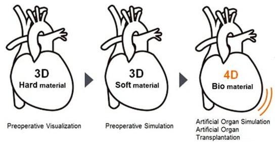
Figure 9.
Evolution of 3D bioprinting.
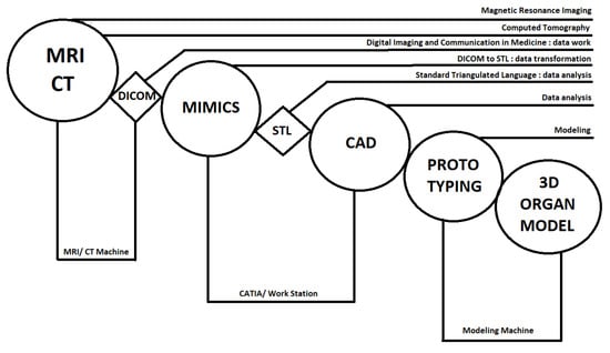
Figure 10.
Technological process of a 3D-printing production applied in regenerative medicine [80].
6. Conclusions
Photopolymerization in 3D printing has been used for applications in fabricating rapid and functional prototypes, customized products, and serial production. Over more than 30 years of development on photopolymerization has made great progress on improving the production methods (SLA, DLP, CDLP/CLIP), production speed, and quality of 3D printed products for industrial and research applications. Material-wise, efforts will further be paid to high-performance resins, especially biocompatible resins, and bioink.
This article serves as a review of vat photopolymerization printing technology and acquaints a wide audience of readers across various disciplines with the possibilities of their use, as well as the advantages and disadvantages of this technology.
In this review, we aimed to summarize all the various types of this technology and the large range of materials used, as well as providing specific applications of this technology in practice, especially in the field of biomedicine and customization. We think that this review is a good follow-up to the already published review of 3D printing, and it is a great addition to this article such that together they form a comprehensive overview of these latest trends in AM.
The future of photopolymerization lies in two main categories: material development, especially in medical applications, and applying modern designing methods. Indeed, there is huge potential for material development and the mathematical modeling of 4D printing using multiphysical properties, i.e., variable surface hardness, shape memory, etc. As for the construction methods, the future lies in fabricating topologically optimized, bionic, and microrod structures.
Applications of 3D printing and, in particular, photopolymerization has spanned across all industries, e.g., in robotics, medicine, dental, engineering, automotive, aerospace, and water resources and related treatments. To conclude, it can be stated that the future of 3D printing is solely limited by the creativity and technical thinking of designers.
Author Contributions
Conceptualization: all authors; M.P. and P.S. conceived the ideas and organized the main content; writing—original draft: M.P., J.M., J.J., and Q.-P.M.; writing—review and editing: J.H., L.J., and Q.-P.M. All authors have read and agreed to the published version of the manuscript.
Funding
This paper was completed in connection with the project “Innovative and additive manufacturing technology—new technological solutions for 3D printing of metals and composite materials,” registration no. CZ.02.1.01/0.0/0.0/17_049/0008407 financed by the Structural Funds of European Union project.
Conflicts of Interest
The authors declare no conflict of interest.
References
- History of Additive Manufacturing. Available online: http://www.wohlersassociates.com/history2014.pdf/ (accessed on 6 February 2020).
- The Free Beginner’s Guide to 3D Printing. Available online: https://3dprintingindustry.com/3d-printing-basics-free-beginners-guide/ (accessed on 6 February 2020).
- History of EOS Company. Available online: https://www.eos.info/about_eos/history/ (accessed on 6 February 2020).
- The Complete History of 3D Printing: From 1980 to the Present Day. Available online: https://3dsourced.com/guides/history-of-3d-printing/ (accessed on 6 February 2020).
- Barron, J.; Wu, P.; Ladouceur, H.; Ringeisen, B. Biological Laser Printing: A Novel Technique for Creating Heterogeneous 3-dimensional Cell Patterns. Biomed. Microdevices 2004, 6, 139–147. [Google Scholar] [CrossRef] [PubMed]
- Derby, B. Printing and Prototyping of Tissues and Scaffolds. Science 2012, 338, 921–926. [Google Scholar] [CrossRef]
- Jang, E.H.; Kim, J.-H.; Lee, J.H.; Kim, D.-H.; Youn, Y.-N. Enhanced Biocompatibility of Multi-Layered, 3D Bio-Printed Artificial Vessels Composed of Autologous Mesenchymal Stem Cells. Polymers 2020, 12, 538. [Google Scholar] [CrossRef] [PubMed]
- Chia, H.; Wu, B. Recent advances in 3D printing of biomaterials. J. Biol. Eng. 2015, 9, 1–14. [Google Scholar] [CrossRef] [PubMed]
- ASTM International. ISO/ASTM 52900:2015 Additive Manufacturing—General Principles—Terminology; ASTM: West Conshohocken, PA, USA, 2015; p. 5. [Google Scholar]
- Fiedor, P.; Pilch, M.; Szymaszek, P.; Chachaj-Brekiesz, A.; Galek, M.; Ortyl, J. Photochemical Study of a New Bimolecular Photoinitiating System for Vat Photopolymerization 3D Printing Techniques under Visible Light. Catalysts 2020, 10, 284. [Google Scholar] [CrossRef]
- Crivello, J.; Reichmanis, E. Photopolymer Materials and Processes for Advanced Technologies. Chem. Mater. 2013, 26, 533–548. [Google Scholar] [CrossRef]
- Phillips, R. Photopolymerization. J. Photochem. 1984, 25, 79–82. [Google Scholar] [CrossRef]
- A Primer on UV-Curable Inkjet Inks. Available online: http://www.signindustry.com/flatbed_UV/articles/2008-11-17-SGIA_Primer_on_UV-Curable_Inkjet_Inks.php3/ (accessed on 6 February 2020).
- Ravve, A. Light-Associated Reactions of Synthetic Polymers; Springer: New York, NY, USA, 2006; ISBN 9780387318035. [Google Scholar]
- Desimone, J.; Alexander, M.; Nikita, E.; Edward, E.; Smulski, T. Continous Liquid Interphase Printing. U.S. Patent PCT/US2014/015506, 21 August 2014. [Google Scholar]
- Tumbleston, J.R.; Shirvanyants, D.; Ermoshkin, N.; Janusziewicz, R.; Johnson, A.R.; Kelly, D.; DeSimone, J.M. Continuous liquid interface production of 3D objects. Science 2015, 347, 1349–1352. [Google Scholar] [CrossRef]
- Huang, B.H.R.; Xue, Z.; Zhao, J.; Li, Q.; Xia, T.; Zhang, W.; Lu, C. Continuous liquid interface production of alginate/polyacrylamide hydrogels with supramolecular shape memory properties. Carbohydr. Polym. 2020, 231, 115736. [Google Scholar] [CrossRef]
- Redwood, B.; Schoöffer, F.; Garet, B. The 3D Printing Handbook: Technologies, Design and Applications; 3D Hubs: Amsterdam, The Netherlands, 2017; ISBN 9789082748505. [Google Scholar]
- Bártolo, P. Stereolithography: Materials, Processes and Applications; Springer: New York, NY, USA, 2011; ISBN 978-0-387-92903-3. [Google Scholar]
- Janusziewicz, R.; Tumbleston, J.R.; Quintanilla, A.L.; Mecham, S.J.; DeSimone, J.M. Layerless fabrication with continuous liquid interface production. Proc. Natl. Acad. Sci. USA 2016, 113, 11703–11708. [Google Scholar] [CrossRef] [PubMed]
- Stereolithography, SLA. Available online: https://www.manufacturingguide.com/en/stereolithography-sla (accessed on 22 July 2020).
- Lemma, E.; Spagnolo, B.; De Vittorio, M.; Pisanello, F. Studying Cell Mechanobiology in 3D: The Two-Photon Lithography Approach. Trends Biotechnol. 2019, 37, 358–372. [Google Scholar] [CrossRef]
- Bass, M. Handbook of Optics: Fundamentals, Techniques, and Design; McGraw-Hill Professional: New York, NY, USA, 1994. [Google Scholar]
- SLA vs. DLP: Guide to Resin 3D Printers. Available online: https://formlabs.com/blog/resin-3d-printer-comparison-sla-vs-dlp/ (accessed on 22 July 2020).
- Zhou, X.; Hou, Y.; Lin, J. A review on the processing accuracy of two-photon polymerization. AIP Adv. 2015, 5, 030701. [Google Scholar] [CrossRef]
- Ostendorf, A.; Chichkov, B.N. Two-photon polymerization: A new approach to micromachining. Photon Spectra 2006, 40, 72. [Google Scholar]
- Using Draft Resin. Available online: https://support.formlabs.com/s/article/Using-Draft-Resin?language=en_US// (accessed on 23 July 2020).
- Standard. Available online: https://formlabs-media.formlabs.com/datasheets/Clear_Resin_Technical.pdf/ (accessed on 23 July 2020).
- Draft Resin. Available online: https://formlabs-media.formlabs.com/datasheets/Draft_DataSheet_.pdf/ (accessed on 23 July 2020).
- Grey Pro. Available online: https://formlabs-media.formlabs.com/datasheets/Grey_Pro_Technical.pdf/ (accessed on 23 July 2020).
- Rigid. Available online: https://formlabs-media.formlabs.com/datasheets/Rigid_Technical.pdf/ (accessed on 23 July 2020).
- High Temp. Available online: https://formlabs-media.formlabs.com/datasheets/High_Temp_Technical.pdf/ (accessed on 23 July 2020).
- Durable. Available online: https://formlabs-media.formlabs.com/datasheets/1801084-TDS-ENUS-0P.pdf/ (accessed on 23 July 2020).
- Tough 1500. Available online: https://formlabs-media.formlabs.com/datasheets/Tough_1500_TDS_EN.pdf/ (accessed on 23 July 2020).
- Elastic. Available online: https://formlabs-media.formlabs.com/datasheets/Elastic_Resin_Technical.pdf/ (accessed on 23 July 2020).
- Flexible. Available online: https://formlabs-media.formlabs.com/datasheets/Flexible_Technical.pdf/ (accessed on 23 July 2020).
- Ceramic. Available online: https://formlabs-media.formlabs.com/datasheets/1907180-TDS-ENUS-0.pdf/ (accessed on 23 July 2020).
- Castable Wax. Available online: https://formlabs-media.formlabs.com/datasheets/Castable_Wax_Technical_Data_Sheet.pdf/ (accessed on 23 July 2020).
- How ROE Dental Lab Pivoted to Manufacturing Medical Supplies to Fight COVID-19. Available online: https://dental.formlabs.com/eu/blog/roe-dental-manufacturing-medical-supplies-swabs-covid-19/ (accessed on 23 July 2020).
- Biomodex. Available online: https://www.biomodex.com/ (accessed on 23 July 2020).
- Dental LT Clear. Available online: https://formlabs-media.formlabs.com/datasheets/Dental_LT_Clear_Technical.pdf/ (accessed on 23 July 2020).
- Dental SG. Available online: https://formlabs-media.formlabs.com/datasheets/DentalSG-DataSheet.pdf/ (accessed on 23 July 2020).
- Surgical Guide. Available online: https://formlabs-media.formlabs.com/datasheets/surgical_guide_technical_data_sheet_en.pdf/ (accessed on 23 July 2020).
- Gopinathan, J.; Noh, I. Recent trends in bioinks for 3D printing. Biomater. Res. 2018, 22, 11. [Google Scholar] [CrossRef]
- A Guide to Matrix Bioinks. Available online: https://www.allevi3d.com/a-guide-to-matrix-bioinks/ (accessed on 23 July 2020).
- Farsari, M.; Chichkov, B. Two-photon fabrication. Nat. Photon. 2009, 3, 450–452. [Google Scholar] [CrossRef]
- Rideell Partners with Carbon to Produce First-Ever 3D Printed Football Helmet Liner. Available online: https://www.carbon3d.com/news/riddell-partners-with-carbon-to-produce-next-gen-football-helmet/ (accessed on 6 February 2020).
- 8sole. Available online: https://www.8sole.com/ (accessed on 6 February 2020).
- Derek Luther: Zahájil jsem evoluci aditivní výroby v Adidasu. Available online: https://www.konstrukter.cz/derek-luther-zahajil-jsem-evoluci-aditivni-vyroby-v-adidasu/ (accessed on 6 February 2020).
- Using 3D Scanning and Printing to Help Children with Ear Deformities. Available online: https://www.artec3d.com/cases/prosthetic-3d-printed-ear-implants/ (accessed on 6 February 2020).
- Sonova’s Custom Hearing Aids are Discreet and Efficiently Made. Available online: https://www.trendhunter.com/trends/3d-printed-hearing-aids/ (accessed on 6 February 2020).
- Nasopharyngeal Swabs. Available online: https://www.carbon3d.com/covid19/ (accessed on 6 December 2020).
- New Light-Touch Supports for Castable Wax Resin in PreForm 3.4.6. Available online: https://formlabs.com/eu/blog/easier-post-processing-jewelry-3d-prints/ (accessed on 23 July 2020).
- Hsieh, T.; Ng, C.B.; Narayanan, K.; Wan, A.; Ying, J. Three-dimensional microstructured tissue scaffolds fabricated by two-photon laser scanning photolithography. Biomaterials 2010, 31, 7648–7652. [Google Scholar] [CrossRef] [PubMed]
- Suzuki, M.; Takahashi, T.; Aoyagi, S. 3D laser lithographic fabrication of hollow microneedle mimicking mosquitos and its characterization. Int. J. Nanotechnol. 2018, 15, 157–173. [Google Scholar] [CrossRef]
- Göring, G.; Dietrich, P.I.; Blaicher, M.; Sharma, S.; Korvink, J.G.; Schimmel, T.; Koos, C.; Hölscher, H. Tailored probes for atomic force microscopy fabricated by two-photon polymerization. Appl. Phys. Lett. 2016, 109, 063101. [Google Scholar] [CrossRef]
- Zhou, L.; Gao, Q.; Fu, J.; Chen, Q.; Zhu, J.; Sun, Y.; He, Y. Multimaterial 3D Printing of Highly Stretchable Silicone Elastomers. ACS Appl. Mater. Interfaces 2019, 11, 23573–23583. [Google Scholar] [CrossRef]
- Valentine, A.; Busbee, T.; Boley, J.; Raney, J.; Chortos, A.; Kotikian, A.; Berrigan, J.; Durstock, M.; Lewis, J. Hybrid 3D Printing of Soft Electronics. Adv. Mater. 2017, 29, 1703817. [Google Scholar] [CrossRef] [PubMed]
- Truby, R.; Lewis, J. Printing soft matter in three dimensions. Nature 2016, 540, 371–378. [Google Scholar] [CrossRef]
- Tawk, C.; in het Panhuis, M.; Spinks, G.; Alici, G. Bioinspired 3D Printable Soft Vacuum Actuators for Locomotion Robots, Grippers and Artificial Muscles. Soft Robot. 2018, 5, 685–694. [Google Scholar] [CrossRef]
- Duoss, E.; Weisgraber, T.; Hearon, K.; Zhu, C.; Small, W.; Metz, T.; Vericella, J.; Barth, H.; Kuntz, J.; Maxwell, R.; et al. Three-Dimensional Printing of Elastomeric, Cellular Architectures with Negative Stiffness. Adv. Funct. Mater. 2014, 24, 4905–4913. [Google Scholar] [CrossRef]
- Bagheri, A.; Jin, J. Photopolymerization in 3D Printing. ACS Appl. Polym. Mater. 2019, 1, 593–611. [Google Scholar] [CrossRef]
- Graeber, G.; Martin Kieliger, O.; Schutzius, T.; Poulikakos, D. 3D-Printed Surface Architecture Enhancing Superhydrophobicity and Viscous Droplet Repellency. ACS Appl. Mater. Interfaces 2018, 10, 43275–43281. [Google Scholar] [CrossRef] [PubMed]
- Gupta, T.; Strelcov, E.; Holland, G.; Schumacher, J.; Yang, Y.; Esch, M.; Aksyuk, V.; Zeller, P.; Amati, M.; Gregoratti, L.; et al. Electron and X-ray Focused Beam-Induced Cross-Linking in Liquids: Toward Rapid Continuous 3D Nanoprinting and Interfacing using Soft Materials. ACS Nano 2020, 14, 12982–12992. [Google Scholar] [CrossRef] [PubMed]
- Cui, H.; Zhu, W.; Holmes, B.; Zhang, L. Biologically Inspired Smart Release System Based on 3D Bioprinted Perfused Scaffold for Vascularized Tissue Regeneration. Adv. Sci. 2016, 3, 1600058. [Google Scholar] [CrossRef] [PubMed]
- Clausen, A.; Wang, F.; Jensen, J.; Sigmund, O.; Lewis, J. Topology Optimized Architectures with Programmable Poisson’s Ratio over Large Deformations. Adv. Mater. 2015, 27, 5523–5527. [Google Scholar] [CrossRef]
- López-Valdeolivas, M.; Liu, D.; Broer, D.; Sánchez-Somolinos, C. 4D Printed Actuators with Soft-Robotic Functions. Macromol. Rapid Commun. 2018, 39, 1700710. [Google Scholar] [CrossRef] [PubMed]
- Zarek, M.; Layani, M.; Cooperstein, I.; Sachyani, E.; Cohn, D.; Magdassi, S. 3D Printing of Shape Memory Polymers for Flexible Electronic Devices. Adv. Mater. 2016, 28, 4449–4454. [Google Scholar] [CrossRef] [PubMed]
- Kelly, B.; Bhattacharya, I.; Heidari, H.; Shusteff, M.; Spadaccini, C.; Taylor, H. Volumetric additive manufacturing via tomographic reconstruction. Science 2019, 363, 1075–1079. [Google Scholar] [CrossRef] [PubMed]
- Chen, M.; Lee, H.; Yang, J.; Xu, Z.; Huang, N.; Chan, B.; Kim, J. Parallel, Multi-Material Electrohydrodynamic 3D Nanoprinting. Small 2020, 16, 1906402. [Google Scholar] [CrossRef] [PubMed]
- Kiefer, P.; Hahn, V.; Nardi, M.; Yang, L.; Blasco, E.; Barner-Kowollik, C.; Wegener, M. Sensitive Photoresists for Rapid Multiphoton 3D Laser Micro- and Nanoprinting. Adv. Opt. Mater. 2020, 8, 2000895. [Google Scholar] [CrossRef]
- Loterie, D.; Delrot, P.; Moser, C. High-resolution tomographic volumetric additive manufacturing. Nat. Commun. 2020, 11, 1–6. [Google Scholar] [CrossRef]
- Robotics, Sensors, & Devices. Available online: https://www.sri.com/robotics-sensors-devices/ (accessed on 12 February 2021).
- Tijing, L.; Dizon, J.; Ibrahim, I.; Nisay, A.; Shon, H.; Advincula, R. 3D printing for membrane separation, desalination and water treatment. Appl. Mater. Today 2020, 18, 100486. [Google Scholar] [CrossRef]
- Kuang, X.; Roach, D.; Wu, J.; Hamel, C.; Ding, Z.; Wang, T.; Dunn, M.; Qi, H. Advances in 4D Printing: Materials and Applications. Adv. Funct. Mater. 2018, 29, 1805290. [Google Scholar] [CrossRef]
- On the Road to 3D Printed Organs. Available online: https://www.the-scientist.com/news-opinion/on-the-road-to-3-d-printed-organs-67187/ (accessed on 6 December 2020).
- Wu, Y.; Heikal, L.; Ferns, G.; Ghezzi, P.; Nokhodchi, A.; Maniruzzaman, M. 3D Bioprinting of Novel Biocompatible Scaffolds for Endothelial Cell Repair. Polymers 2019, 11, 1924. [Google Scholar] [CrossRef] [PubMed]
- Hospodiuk, M.; Dey, M.; Sosnoski, D.; Ozbolat, I.T. The bioink: A comprehensive review on bioprintable materials. Biotechnol. Adv. 2017, 35, 217–239. [Google Scholar] [CrossRef] [PubMed]
- Mironov, V.; Boland, T.; Trusk, T.; Forgacs, G.; Markwald, R.R. Organ printing: Computer-aided jet-based 3D tissue engineering. Trends Biotechnol. 2003, 21, 157–161. [Google Scholar] [CrossRef]
- Kunimoto, K. Turn to the Future for Living Body Medical Design. In Proceedings of the Simulation Community Conference “Science in the Age of Experience” 2017, Chicago, IL, USA, 15–18 May 2017. [Google Scholar]
Publisher’s Note: MDPI stays neutral with regard to jurisdictional claims in published maps and institutional affiliations. |
© 2021 by the authors. Licensee MDPI, Basel, Switzerland. This article is an open access article distributed under the terms and conditions of the Creative Commons Attribution (CC BY) license (http://creativecommons.org/licenses/by/4.0/).