Abstract
This paper attempts to validate the application of the Virtual Isotropic Material Concept (VIMC) in combination with the average strain energy density (ASED) criterion to predict the critical load in notched laminated composites. This methodology was applied to E/glass–epoxy-laminated composites containing U-notches. For this purpose, a series of fracture test data recently published in the literature on specimens with different notch tip radii, lay-up configurations, and a number of plies were employed. It was shown that the VIMC–ASED combined approach provided satisfactory predictions of the last-ply failure (LPF) loads (i.e., critical loads).
1. Introduction
Within the field of engineering materials, composites have achieved significant prominence in the last few decades, its strength-to-weight ratio being one of the most relevant characteristics, so that it has become a perfect material in industries such as aerospace and automotive. A composite can be defined as that material resulting from the mixing of two or more constituent materials with significantly different properties (physical or chemical), which remain separate and distinct on a macroscopic level once the composite is formed, and generate a (composite) material with superior performance [1].
Among the different types of composites, continuous fibre-reinforced laminated composites stand out. They offer not only a high strength-to-weight ratio but may also have exceptional properties such as high durability, stiffness, flexural strength, and resistance to corrosion, wear, impact, and fire, among others. These composites have (generally) orthotropic mechanical properties, which, on the one hand, tend to present the best overall performance (compared to other types of composites) but, on the other hand, may deal with unique failure mechanisms that may be difficult to analyse (e.g., delamination or micro buckling). In any case, they are being used more and more as an alternative to other conventional materials, even for primary structural purposes [2].
Moreover, in many structural applications, components can be designed with different types of stress raisers (e.g., holes, notches, cut-outs), generating areas that are prone to crack initiation, and with the consequent loss of load-bearing capacity. Stress risers may also appear due to fabrication defects or operation damage. In any case, being able to predict accurately the load-bearing capacity (e.g., last-ply failure load) of laminated composites containing stress risers is essential for structural integrity purposes.
Conventionally, structural integrity assessment procedures or methodologies (e.g., [3,4,5]) address the analysis of crack-type defects. If they are directly applied to components containing notch-type defects, assuming that this type of defect behaves as cracks, they provide (mostly) over conservative results, due to the well-known notch effect (e.g., [6,7,8,9]). Thus, a great deal of research has been done to find specific methodologies for the assessment of notches. The different fracture theories that can be found in the literature dealing with the notch effect can be grouped into three different categories: (a) the global criterion [10,11,12], based on linear-elastic notch fracture mechanics, establishes that fracture occurs when the notch stress intensity factor reaches a critical value; (b) the local criteria, which bring together a series of approaches (e.g., the theory of critical distances (TDC) or the average strain energy density (ASED)) that have in common the analysis of the stress, strain, or energy fields at the defect tip. This paper focused, precisely, on the ASED criterion, which was validated in a wide range of materials [13,14,15]; (c) finally, the progressive damage models [16,17,18], which consider the material damage during the entire loading process, and the consequent changes in the stress distribution. The main issue found in the application of any of these failure models in laminated composites was to consider their orthotropic behaviour, the ply-by-ply analysis, and the first ply failure predictions, resulting in complex and time-consuming processes.
Recently, Torabi and Pirhadi developed a novel method to simplify the analysis of laminated composites, the so-called Virtual Isotropic Material Concept (VIMC). The authors successfully applied the VIMC on glass/epoxy-notched laminated composites containing U- and V-notches, in combination with two well-known brittle stress criteria: the maximum tangential stress (MTS) criterion and the mean stress (MS) criterion, to predict the last-ply failure (LPF) loads under both mode I and mixed-mode I/II loadings [19,20,21,22,23].
With all this, and based on the experimental results published by Torabi and Pirhadi in [19], this paper attempted to expand the use of VIMC to analyse U-notched laminated composites in combination with the energetic ASED criterion. Thus, Section 2 provides the theoretical framework of the work, including a description of both the VIMC and the ASED criterion. Section 3 presents the materials and methods used for the prediction of LPF load of U-notched laminated composites. Section 4 gathers the experimental results and provides the LPF load predictions provided by the proposed methodology, together with the corresponding discussion. Finally, Section 5 presents the main conclusions.
2. Theoretical Background
2.1. The ASED Criterion
The average strain density energy (ASED) criterion, whose fundamentals were developed by Shi [24], assumes that, under mode I loading, fracture occurs when the average value of the strain energy density () over a certain control volume (defined by radius R0, see Figure 1) reaches a critical value (1) [25]:
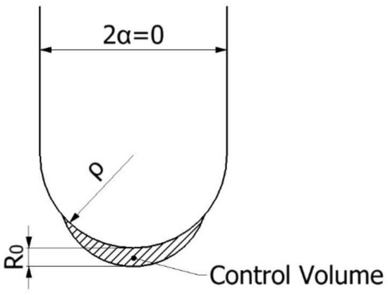
Figure 1.
Control volume (area) for U-notch (2α = 0) under mode I loading.
When the material exhibits linear-elastic behaviour, Wc is directly provided by Equation (2), as proposed in [25].
σu being the ultimate tensile strength and E being Young’s modulus.
When the notch opening angle is zero (2α = 0, see Figure 1), as occurs in the case of cracks or U-notch, R0 can be defined in terms of the fracture toughness (Kc), the ultimate tensile strength (σu), and the Poisson’s ratio (υ). If the material is operating under plane strain conditions, R0 is expressed by Equation (3), while under plane stress conditions, R0 is given by Equation (4).
Those situations between plane strain and plane stress conditions require interpolation between Equations (3) and (4) to define R0. In this sense, Equation (5) indicates the upper limit of fracture resistance where plane strain conditions may be considered to be dominant [6]:
Analogously, the onset of plane stress conditions is attained when the fracture resistance exceeds the value given by Equation (6) [6]:
σy being the yield or proof strength, and B being the specimen thickness. For those situations in which the fracture resistance value is located within these two limits, R0 may be obtained by interpolation between Equations (3) and (4).
Once R0 is known, the ASED criterion requires the average strain energy density () to be derived within the corresponding control volume. Lazzarin and Berto [9] derived a useful, straightforward analytical expression, gathered in Equation (7):
where F is a function that depends on the notch opening angle (2α) and whose values are gathered in [9]. For this work, it sufficed to say that for U-shaped notches (2α = 0°) F is equal to 0.785. Furthermore, H is another function depending on notch geometry (opening angle and notch radius) and material properties (R0 and, thus, fracture toughness, ultimate tensile strength, and Poisson´s ratio), whose values (for U-notch type defect) may easily be obtained from Table 1 [9]. Finally, σmax is the maximum stress at the notch tip at fracture conditions.

Table 1.
Values of H for U-shaped notches [9].
With all these Equations (1)–(7), it is straightforward to assess notched components according to the ASED fracture criterion. The results shown in the literature reveal the accuracy of this approach as long as the material being analysed presents a linear-elastic behaviour (e.g., [9,13,14,15])
2.2. The Virtual Isotropic Material Concept
The main assumption of the VIMC is that it equates a real laminated composite with orthotropic behaviour to a virtual brittle plate of the same geometry with isotropic behaviour [21]. Once this is done, if the VIMC is correct, well-known fracture methodologies (e.g., TCD, ASED) can be directly applied.
A review of the literature dealing with the fracture analysis of engineering materials containing notches revealed that there are two essential material parameters: the characteristic strength (σf) and the fracture toughness (Kc). The characteristic strength is also referred to as the critical stress or the inherent strength, depending on the approach, and, assuming fully linear-elastic conditions, is generally assumed to be equal to the material ultimate tensile strength (e.g., see Equations (2)–(4). The VIMC, at the same time, requires (just) two important properties of the laminated composite to be defined, namely the ultimate tensile strength (σu) and the trans-laminar fracture toughness (KTL). The correct definition of these two properties is the main issue of the application of the VIMC. As soon as they are known, they are considered as the Kc and the σf of the virtual isotropic material, and the notch assessment (in terms of LPF load predictions) of the laminated composite being analysed follows the same methodologies used for isotropic materials. Thus, it should be noted that, when using the VIMC, it is not required to perform a large experimental program to determine the mechanical properties in different directions, such as longitudinal Young´s modulus (Ex), lateral Young´s modulus (Ey), in-plane Poisson´s ratio (υxy), or shear elastic modulus (Gxy).
Summarising, once the material characterisation difficulty has been overcome, the application of any of the well-known brittle fracture criteria (e.g., ASED criterion) can go ahead simply by using the obtained values of σu and KTL as σf and Kc, respectively. The VIMC is, then, a relevant tool to facilitate the prediction of the critical loads of brittle or quasi-brittle laminated composites (e.g., E/glass–epoxy-laminated composites).
3. Materials and Methods
The VIMC–ASED criterion was applied here to fibre-reinforced laminated E/glass–epoxy composites. The entire experimental program was previously conducted by Torabi and Pirhadi, whose results were published in [21], where the reader may find additional details to those gathered here.
The laminated composites were manufactured using E-glass fibre (between 56% and 59% of fibre volume), epoxy resin (Epon 828), and Siclo-Aliphatic-Amin hardener. The resulting composite plates were fabricated using the vacuum bag-autoclave moulding technique, including bleeders located on the top and bottom surfaces. In order to validate the VIMC–ASED methodology independently of the composite structure, layers with three different fibre orientations (unidirectional (0)s, cross-ply (0/90/0/90)s, and quasi-isotropic (0/90/±45)s and two different numbers of layers (8-ply and 16-ply) were utilised. These generated 6 different material conditions. The thickness of each lamina was approximately 0.28 mm, with the total thickness of each laminate configuration being between 2.9 mm and 3.1 mm for 8 layers, and between 5.6 mm and 5.8 mm for the 16-layer specimens. With these different thicknesses, it was possible to determine whether the VIMC–ASED criterion proposed in this work was independent of the number of layers.
The experimental program encompasses three different types of tests. Two of them (characterisation tests) were completed for the material characterisation (σu and KTL) itself, which was subsequently used as an input for the VIMC–ASED analysis. The last type (validation tests) consisted of fracture tests of laminated composites weakened by U-notches in order to determine the LPF loads and compare them with the VIMC–ASED predictions. Figure 2 shows some of the U-notched composite samples after LPF.
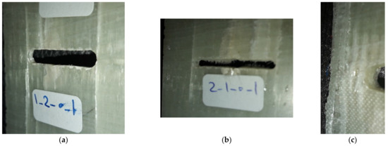
Figure 2.
Some of the U-notched composite samples after last-ply failure (LPF). (a) Unidirectional, (b) cross-ply, and (c) quasi-isotropic configurations.
In the unidirectional composite (Figure 2a), local damage first nucleated from the notch tip, then grew slowly during loading, and, finally, it reached the long fibres that were oriented perpendicular to the damage growth direction. As a result, at the onset of LPF, a long crack parallel to the fibres was recognised in the U-notch neighbourhood. In Figure 2b,c, corresponding to the cross-ply and quasi-isotropic lay-ups, different patterns were observed at LPF onset. The main difference between the failure pattern of the unidirectional configuration with the patterns of the two other configurations was that in the unidirectional composite, the pattern was mainly longitudinal and no lateral pattern could be recognised, whereas, in the two latter cases, failure patterns were both longitudinal and lateral due to the presence of 90° plies in the lay-up.
As explained before, only two parameters are necessary to completely describe the VIMC, namely the ultimate tensile strength (σu) and the trans-laminar fracture toughness (KTL) of the real laminated composite. σu was obtained, for each laminated composite, through a tensile test at a loading rate of 2 mm/min, utilising unnotched samples, following the test procedure and the requirements of sample geometry specified in the standard ASTM D3039 [26]. Additionally, the bulk value of E was calculated by the same tensile test. Moreover, the KTL parameter was determined by fracture tests on pre-cracked samples according to the standard ASTM E1922 [27]. The single-edge narrow notches (i.e., the pre-cracks) in the compact-tension (CT)-like specimens suggested by ASTM E1922 [27] were introduced by using a diamond wheel cutter with a thickness of 0.3 mm, fulfilling the standard geometrical conditions (see [21] for details). In both tensile and fracture characterisation tests, three specimens were tested per lay-up configuration.
After characterisation tests, validation tests were completed. The objective was to complete the experimental tests on the U-notched specimens and to compare the critical load (LPF load) with the predictions provided by the VIMC–ASED combined criterion. The main dimensions of the notched specimens are shown in Figure 3, with ρ being the notch tip radius and taking values of 1, 2, and 4 mm. Again, further details may be found in [21].
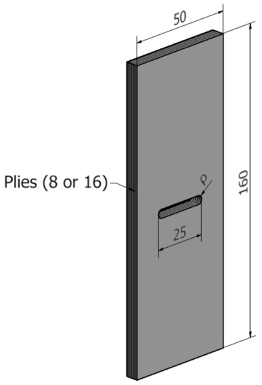
Figure 3.
Schematic of the U-notched laminated composite specimen. All dimensions are in mm. The lay-up configurations are (0)s, (0/90/0/90)s, and (0/90/±45)s.
Once the whole experimental program was completed, the predictions of critical (LPF) loads in E/glass–epoxy-laminated composites using the VIMC–ASED criterion were derived. As seen above, the application of the ASED criterion depends on several material properties, such as the fracture toughness, the ultimate tensile strength, Young’s modulus, and the Poisson´s ratio. Whereas the three first parameters were directly derived from the experimental program (tensile and fracture tests), the Poisson´s ratio was not determined experimentally in the original tests [21]. Consequently, this parameter was selected from the literature, and this was accompanied by a sensitivity analysis on the influence of the Poisson´s ratio being selected in the final LPF load predictions.
Considering the mechanical properties provided by the VICM, it was straightforward to calculate the critical strain energy (Wc; Equation (2)). This Wc must be compared with the average strain energy density () within the control volume (R0), a process requiring the following steps:
- -
- Determine R0, considering the material properties of the VIMC. R0 follows Equation (3) or (4), depending on the plane strain vs. plane stress conditions. Equations (5) and (6) allowed the limits for both conditions to be estimated, and, in case of intermediate situations, linear interpolation may be used to derive R0.
- -
- The F function (see Equation (7)) was assumed to be equal to 0.785, given that in all the tested notched specimens 2α = 0.
- -
- The value of the H function was derived from Table 1 for each material and notch radius.
- -
- The maximum stress (σmax,VIMC–ASED) at the notch tip was the only unknown in Equation (7), so it may be directly derived for each material and notch radius. Here, it should be noted that σmax,VIMC–ASED corresponded to the stress state at critical conditions (i.e., when the LPF load is applied).
Finally, in order to obtain the critical loads provided by the VIMC–ASED criterion (PVIMC–ASED), the notched fracture specimens were modelled and analysed by finite element analysis (FEA). The simulations were performed in linear-elastic conditions using the finite element software ANSYS 19.2 (Ansys Inc, Canonsburg, PA, USA). The three-dimensional models were partitioned, obtaining a structured mesh composed of 20-node hexahedron elements (see Figure 4a). Additionally, the mesh around the notch tip was refined (minimum element about 0.03 mm), making sure to correctly capture the high-stress gradients generated by the notches (see Figure 4b). The simulation was performed with half of the model taking advantage of the symmetry (although one-quarter of the specimens would have been enough, the computational effort of considering one half was actually very limited). A unit load was applied at the top face (0.5 N in the half being considered), whereas the bottom face was fixed and the nodes belonging to the symmetric face were restrained in the perpendicular direction of the symmetry plane. With all this, the maximum principal stress in the notch root was obtained for the unit load (σmax,UL). The predictions of PVIMC–ASED were obtained by linearly scaling the values obtained from the FEA until the maximum stress values provided by VICM–ASED criterion are reached:
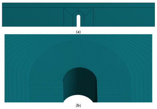
Figure 4.
(a) Structured mesh used for the 3D model; (b) detail of the mesh near the notch tip.
4. Results and Discussion
The mechanical properties (average values) obtained in the experimental characterisation program are gathered in Table 2 [21]. These properties, obtained from conventional tensile and fracture tests, were the only required inputs of the VIMC. It may be observed that there were slight effects of the number of plies and significant effects of the fibre orientation. 16-ply materials had a tendency to generate slightly higher ultimate tensile strength and Young´s modulus than 8-ply materials, which on the contrary tended to develop higher values of KTL. This latter observation may be more related to the different conditions of plane stress/plane strain between the two different ply numbers. Concerning the fibre orientation, unidirectional orientation developed higher material properties (both tensile and fracture), whereas cross-ply and quasi-isotropic orientation presented less significant differences between them. Unidirectional specimens (0) had the best material properties as a result of the relation between the stress state and fibre direction, given that the fibres were precisely oriented in the same direction as the tensile stresses causing the fracture process.
Table 2.
Mechanical properties of the different ply configurations employed [21].
The experimental results of the validation fracture tests (critical or LPF loads) for the three lay-up configurations are shown in Table 3. Similarly to fracture characterisation tests, it could be observed how the unidirectional lay-up configuration developed higher critical loads, but some further observations may be made:
- -
- The Cross-ply lay-up configuration, which presents the lowest values of KTL, also developed the lowest critical loads in the validation fracture tests.
- -
- The critical loads for the 16-ply specimens were not double those obtained for 8-ply samples. These agreed with the higher fracture toughness observed in thinner specimens, much closer to plane stress conditions.
- -
- The notch effect (i.e., increase in critical load with the notch tip radius) existed in all conditions, but it was not very pronounced. Fracture loads in specimens with a notch radius of 1 mm were approximately 15–20% lower than those developed by specimens with a notch radius of 4 mm.
- -
- Most of the notch effects were observed when comparing the critical loads of specimens with notch radii of 1 mm and 2 mm. The differences observed between specimens with notch radii of 2 mm and 4 mm were significantly less.
Table 3.
Experimental critical loads of U-notched specimens for each lay-up configuration [21].
Table 3.
Experimental critical loads of U-notched specimens for each lay-up configuration [21].
| Lay-Up Configuration | ρ (mm) | Number of Layers | PExp (kN) |
|---|---|---|---|
| Unidirectional (0) | 1 | 8-ply | 23.70 |
| 2 | 26.30 | ||
| 4 | 27.40 | ||
| 1 | 16-ply | 41.70 | |
| 2 | 43.90 | ||
| 4 | 44.20 | ||
| Cross-ply (0/90/0/90) | 1 | 8-ply | 14.30 |
| 2 | 16.90 | ||
| 4 | 17.20 | ||
| 1 | 16-ply | 26.80 | |
| 2 | 29.10 | ||
| 4 | 29.85 | ||
| Quasi-isotropic (0/90/0/±45) | 1 | 8-ply | 16.50 |
| 2 | 18.30 | ||
| 4 | 18.90 | ||
| 1 | 16-ply | 26.50 | |
| 2 | 29.80 | ||
| 4 | 30.90 |
Table 4 gathers the VIMC–ASED predictions for the critical loads (PVIMC–ASED), together with the different inputs of the analysis. The material properties used in the analysis were those gathered in Table 2, and the Poisson´s ratio considered here was 0.2, according to the literature [28,29]. In any case, a sensitivity analysis was performed to check how the Poisson´s ratio affected the final predictions, revealing that results were not particularly sensitive to the specific value used in this parameter (e.g., considering a Poisson’s ratio of 0.25 generated variation of approximately 0.04% in PVIMC–ASED predictions). Finally, it is also important to mention that, in most cases, the values of KTL (see Table 2) were found between the plane strain limit (Equation (5)) and the plane stress onset (Equation (6) and, thus, R0 was obtained by linear interpolation between Equations (3) and (4).
Table 4.
Average strain energy density (ASED) parameters together with the Virtual Isotropic Material Concept (VIMC)–ASED critical loads.
Figure 5, Figure 6 and Figure 7 compare the experimental results with the corresponding VIMC–ASED predictions, revealing good accuracy for the different lay-up configurations. Further, all the estimated values were within the scatter of ±20% accepted in the fracture mechanics research field [6,7,8,9]. The average deviation from the experimental results was +0.4% for the unidirectional composite, −2.4% for the cross-ply composite, and −2.7% in the case of the quasi-isotropic composite, the highest deviation being −18%, −8.6%, and −19.8% for unidirectional, cross-ply, and quasi-isotropic lay-ups, respectively. Moreover, the accuracy was adequate for both 8-ply and 16-ply materials, although there was a tendency to provide conservative predictions (PVIMC–ASED < Pexperimental) for 8-ply materials and slightly non-conservative predictions in the case of 16-ply materials.
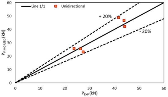
Figure 5.
Comparison between the critical load prediction and experimental results in unidirectional specimens (0).
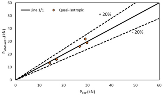
Figure 6.
Comparison between the critical load prediction and experimental results in quasi-isotropic specimens (0/90/±45).
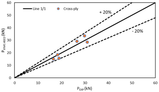
Figure 7.
Comparison between the critical load prediction and experimental results in cross-ply specimens (0/90/0/90).
It may also be observed that the predictions often generated lower critical loads when the notch tip radius increased. This was caused by the interpolation process when obtaining R0 and, although this was contrary to empirical observations, it provided a correction based on the plane stress vs. plane strain situations which, overall, improved the general accuracy of the predictions.
5. Conclusions
This paper proposed and validated a methodology for the prediction of critical loads (or LPF loads) in E/glass–epoxy laminated composites weakened by U-notches. The methodology was based on the combined use of the Virtual Isotropic Material Concept and the average strain energy density criterion.
The VIMC allowed the material’s mechanical properties on laminated composites to be sufficiently defined by simply testing both tensile and pre-cracked fracture specimens, obtaining the corresponding ultimate tensile strength (σu), and trans-laminar fracture toughness (KTL), respectively. The real laminated composite material was then substituted by a virtual isotropic one, whose analysis was performed as it is usually done in isotropic materials. This procedure was completed in this work for different lay-up configurations (unidirectional, cross-ply, and quasi-isotropic) and numbers of plies. Then, for the same lay-up configurations and number of plies, validation U-notched specimens with three different notch radii were tested to determine the corresponding experimental critical loads, which were finally compared with the predictions provided by the VIMC–ASED combined criterion.
The VIMC–ASED combined criterion provided accurate predictions of the critical loads for the different lay-up configurations and a number of plies. This allowed the fracture loads of U-notched composite laminates to be simply estimated by using conventional approaches used in isotropic materials.
Author Contributions
Conceptualisation, S.C. and A.R.T.; methodology, S.C., M.S., A.R.T. and M.R.A.; formal analysis, S.C. and M.S.; investigation, M.S. and S.C.; writing—original draft preparation, M.S.; writing—review and editing, M.S., S.C., A.R.T., and M.R.A. All authors have read and agreed to the published version of the manuscript.
Funding
This research received no external funding.
Institutional Review Board Statement
Not applicable.
Informed Consent Statement
Not applicable.
Data Availability Statement
The data presented in this study are available on request from the corresponding authors.
Conflicts of Interest
The authors declare no conflict of interest.
References
- Rajak, D.K.; Pagar, D.D.; Menezes, P.L.; Linul, E. Fiber-reinforced polymer composites: Manufacturing, properties, and applications. Polymers 2019, 11, 1167. [Google Scholar] [CrossRef]
- Anderson, T.L. Fracture Mechanics: Fundamentals and Applications, 4th ed.; CRC press: Boca Raton, FL, USA, 2005; ISBN 1498728146. [Google Scholar]
- Kocak, M.; Webster, S.; Janosch, J.J.; Ainsworth, R.A.; Koers, R. FITNET Fitness-for-Service (FFS) Procedure; GKSS: Hamburg, Germany, 2008; Volume 1. [Google Scholar]
- British Standards Institution. Guide to Methods for Assessing The Acceptability of Flaws in Metallic Structures; BS7910; British Standards Institution: London, UK, 2019; ISBN 0580601080. [Google Scholar]
- Energy, E. R6: Assessment of The Integrity of Structures Containing Defects, Rev. 4; EDF Energy: Gloucester, UK, 2015. [Google Scholar]
- Taylor, D. The Theory of Critical Distances: A New Perspective in Fracture Mechanics; Elsevier: London, UK, 2007; ISBN 978-0-08-044478-9. [Google Scholar]
- Cicero, S.; Madrazo, V.; García, T.; Cuervo, J.; Ruiz, E. On the notch effect in load bearing capacity, apparent fracture toughness and fracture mechanisms of polymer PMMA, aluminium alloy Al7075-T651 and structural steels S275JR and S355J2. Eng. Fail. Anal. 2013, 29, 108–121. [Google Scholar] [CrossRef]
- Cicero, S.; Madrazo, V.; García, T. On the assessment of U-shaped notches using Failure Assessment Diagrams and the Line Method: Experimental overview and validation. Theor. Appl. Fract. Mech. 2015, 80, 235–241. [Google Scholar] [CrossRef]
- Berto, F.; Lazzarin, P. Recent developments in brittle and quasi-brittle failure assessment of engineering materials by means of local approaches. Mater. Sci. Eng. R Rep. 2014, 75, 1–48. [Google Scholar] [CrossRef]
- Beaumont, P.W.R. The failure of fibre composites: An overview. J. Strain Anal. Eng. Des. 1989, 24, 189–205. [Google Scholar] [CrossRef]
- Waddopus, M.E.; Eisenmann, J.R.; Kaminski, B.E. Macroscopic Fracture Mechanics of Advanced composite materials. J. Compos. Mater. 1996, 22, 4–9. [Google Scholar] [CrossRef]
- Bäcklund, J.; Aronsson, C.G. Tensile Fracture of Laminates with Holes. J. Compos. Mater. 1986, 20, 259–286. [Google Scholar] [CrossRef]
- Justo, J.; Castro, J.; Cicero, S. Energy-based approach for fracture assessment of several rocks containing U-shaped notches through the application of the SED criterion. Int. J. Rock Mech. Min. Sci. 2018, 110, 306–315. [Google Scholar] [CrossRef]
- Ibáñez-Gutiérrez, F.T.; Cicero, S.; Madrazo, V.; Berto, F. Fracture Loads Prediction on Notched Short Glass Fibre Reinforced Polyamide 6 Using the Strain Energy Density. Phys. Mesomech. 2018, 21, 165–172. [Google Scholar] [CrossRef]
- Cicero, S.; Berto, F.; Ibáñez-Gutiérrez, F.T.; Procopio, I.; Madrazo, V. SED criterion estimations of fracture loads in structural steels operating at lower shelf temperatures and containing u-notches. Theor. Appl. Fract. Mech. 2017, 90, 234–243. [Google Scholar] [CrossRef]
- Nguyen, B.N. Three-Dimensional Modeling of Damage in Laminated Composites Containing a Central Hole. J. Compos. Mater. 1997, 31, 122–136. [Google Scholar] [CrossRef]
- Chang, K.Y.; Llu, S.; Chang, F.K. Damage Tolerance of Laminated Composites Containing an Open Hole and Subjected to Tensile Loadings. J. Compos. Mater. 1991, 25, 274–301. [Google Scholar] [CrossRef]
- Lawcokc, G.; Lin, Y.; Mai, Y.W. Progressive Damage and Residual Strength of a Carbon Fibre Reinforced Metal Laminate. J. Compos. Mater. 1997, 31, 928–940. [Google Scholar]
- Torabi, A.R.; Pirhadi, E. Experimental verification of the virtual isotropic material concept for the last-ply-failure of U-notched quasi-isotropic E-glass/epoxy composite laminates under tension-shear loading. J. Ind. Text. 2020. [Google Scholar] [CrossRef]
- Torabi, A.R.; Pirhadi, E. Extension of the virtual isotropic material concept to mixed mode I/II loading for predicting the last-ply-failure of U-notched glass/epoxy laminated composite specimens. Compos. Part B Eng. 2019, 176, 107287. [Google Scholar] [CrossRef]
- Torabi, A.R.; Pirhadi, E. Notch failure in laminated composites under opening mode: The Virtual Isotropic Material Concept. Compos. Part B Eng. 2019, 172, 61–75. [Google Scholar] [CrossRef]
- Torabi, A.R.; Pirhadi, E. On the ability of the notch fracture mechanics in predicting the last-ply-failure of blunt V-notched laminated composite specimens: A hard problem can be easily solved by conventional methods. Eng. Fract. Mech. 2019, 217, 106534. [Google Scholar] [CrossRef]
- Torabi, A.R.; Pirhadi, E. Failure analysis of round-tip V-notched laminated composite plates under mixed mode I/II loading. Theor. Appl. Fract. Mech. 2019, 104, 102342. [Google Scholar] [CrossRef]
- Sih, G.C. Strain-energy-density factor applied to mixed mode crack problems. Int. J. Fract. 1974, 10, 305–321. [Google Scholar] [CrossRef]
- Lazzarin, P.; Zambardi, R. A finite-volume-energy based approach to predict the static and fatigue behavior of components with sharp V-shaped notches. Int. J. Fract. 2001, 112, 275–298. [Google Scholar] [CrossRef]
- ASTM International. Standard Test. Method for Tensile Properties of Polymer Matrix Composite Materials; ASTM D3039/D3039M-17; ASTM International: West Conshohocken, PA, USA, 2017. [Google Scholar]
- ASTM International. Standard Test. Method for Translaminar Fracture Toughness of Laminated and Pultruded Polymer Matrix Composite Materials; ASTM E1922-04; ASTM International: West Conshohocken, PA, USA, 2015. [Google Scholar]
- Khashaba, U.A. In-plane shear properties of cross-ply composite laminates with different off-axis angles. Compos. Struct. 2004, 65, 167–177. [Google Scholar] [CrossRef]
- Selmy, A.I.; Elsesi, A.R.; Azab, N.A.; Abd El-baky, M.A. Monotonic properties of unidirectional glass fiber (U)/random glass fiber (R)/epoxy hybrid composites. Mater. Des. 2011, 32, 743–749. [Google Scholar] [CrossRef]
Publisher’s Note: MDPI stays neutral with regard to jurisdictional claims in published maps and institutional affiliations. |
© 2021 by the authors. Licensee MDPI, Basel, Switzerland. This article is an open access article distributed under the terms and conditions of the Creative Commons Attribution (CC BY) license (http://creativecommons.org/licenses/by/4.0/).