
Mechanical Behavior of Foam-Filled Bamboo Composite Tubes under Axial Compression


Abstract
:1. Introduction
2. Materials
2.1. Bamboo Slices
2.2. Polyurethane Foam
3. Experimental Program
3.1. New Composite Tube
- (1)
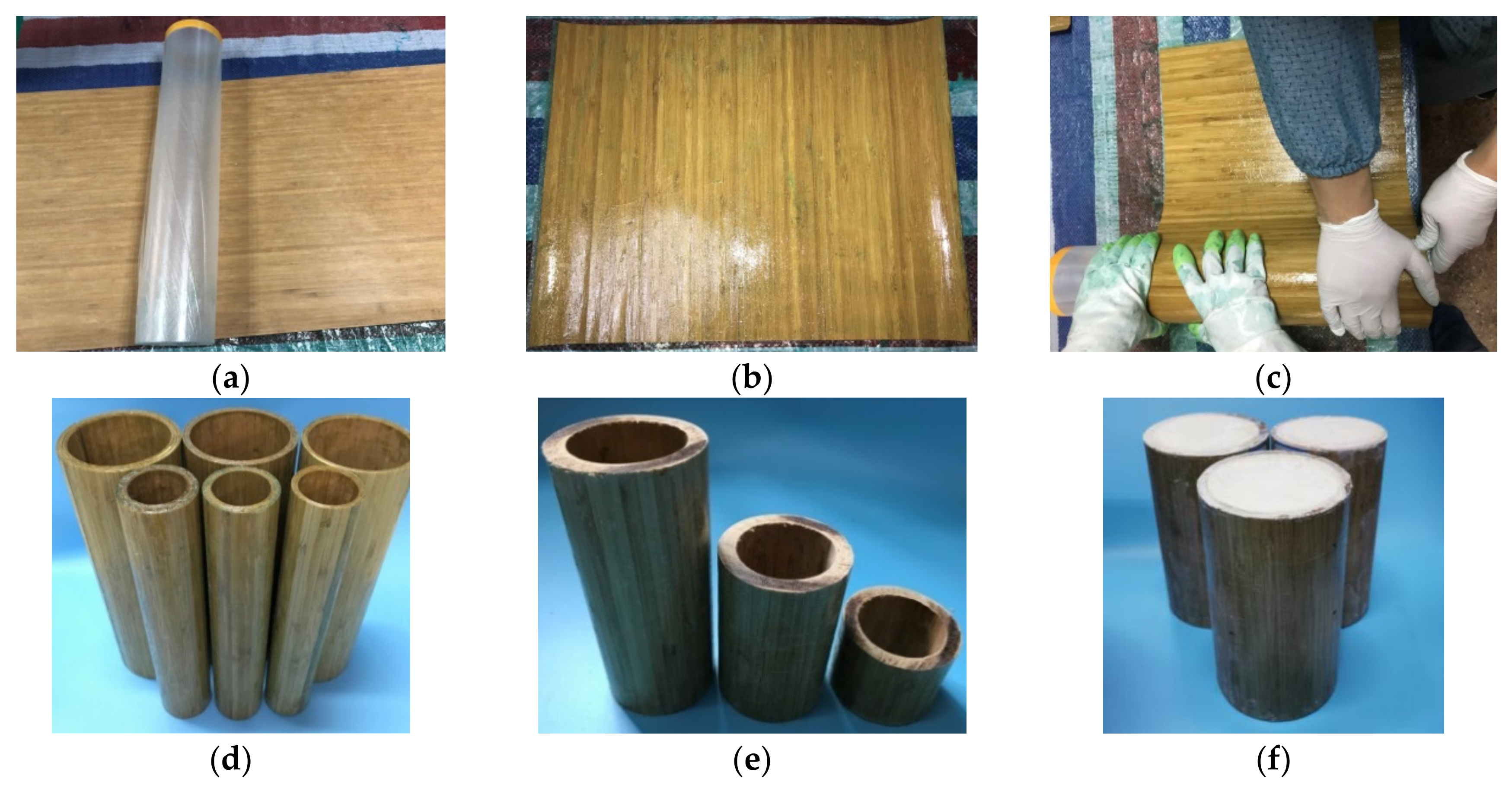
- Preparation of raw materials: The finished side of pressed carbonized unidirectional bamboo slices, epoxy resin and several acrylic tube molds are the raw materials. The size of the bamboo slice is 360 mm × 450 mm, and the circular bamboo fiber tube is a continuous bamboo slice connected end to end. The surface of the bamboo slice is cleaned before production, and a layer of plastic film is wrapped around the acrylic tube mold to facilitate demolding in a later stage.
- (2)
- Soakage of epoxy resin: The bamboo slices are laid flat on the working surface, both sides of the bamboo slices are soaked with the epoxy resin, and the operation is repeated until the epoxy resin saturates the bamboo slices.
- (3)
- Winding of bamboo slices: The bamboo slices are tightly wrapped around the acrylic tube mold to ensure that the direction of bamboo fiber is parallel to the axis of the acrylic tube. There is no lap connection between two bamboo slices, and they are wound in turn and repeatedly squeezed to eliminate the interlayer gap. After wrapping the bamboo slices according to the number of layers, several layers of protective film are wrapped around them to prevent the bamboo slices from curling.
- (4)
- Demolding and curing: The wrapped bamboo composite tube is placed at room temperature and left until the epoxy resin is completely hardened and separated from the acrylic tube. It is then placed at room temperature for curing.
- (5)
- Cutting and polishing: The bamboo composite tube is cut according to the design height, and both ends are polished to ensure that there are no uneven ends of the composite tube.
- (6)
- Foam filling: The foam material components are mixed in equal proportions and then poured into the bamboo composite tube. The two ends of the tube are compacted by heavy objects and left for 10 min for natural foaming. When the volume no longer changes, the heavy objects are removed, and the specimen is finished.
3.2. Specimen Preparation
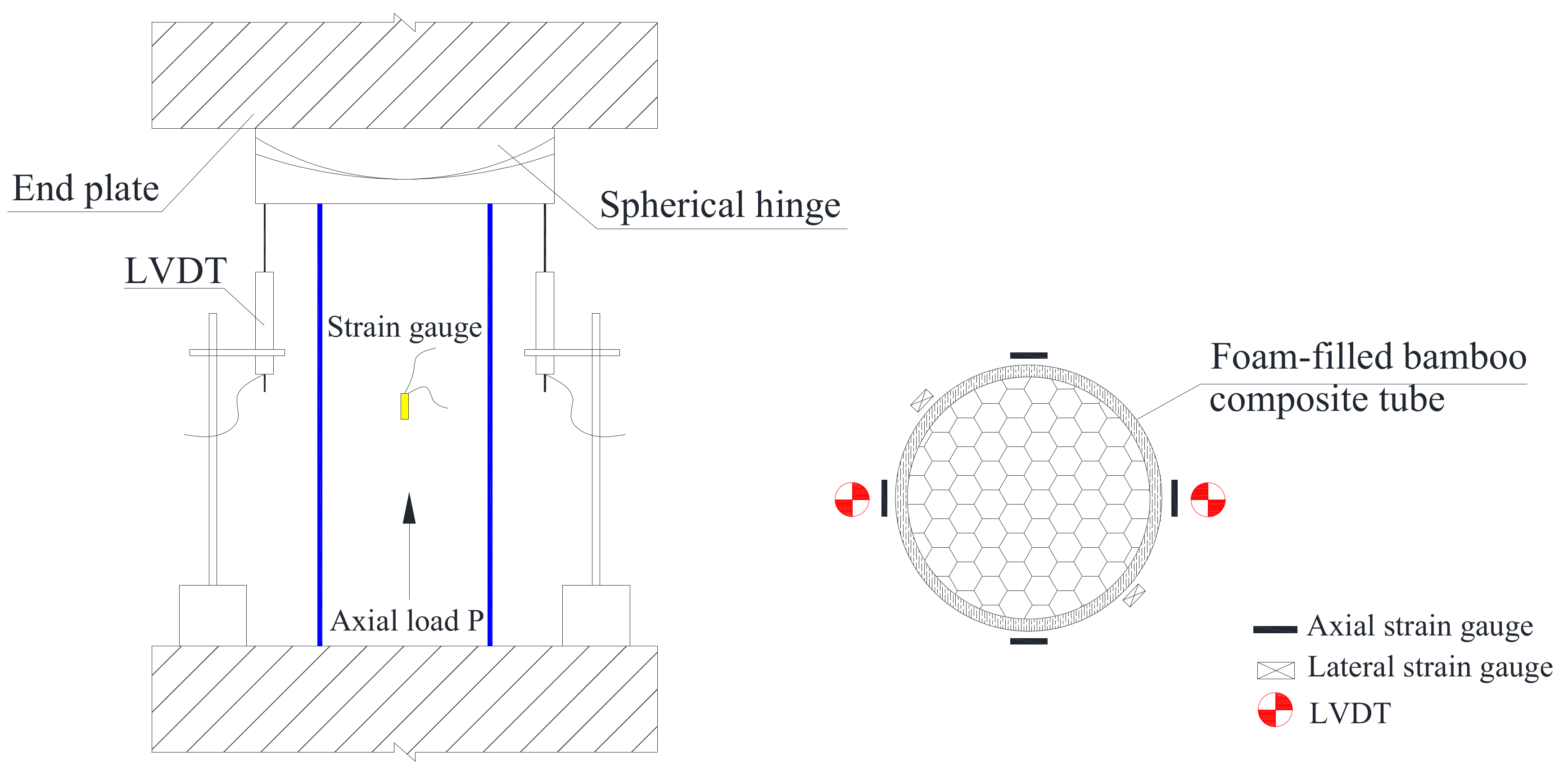
3.3. Mechanical Testing Setup and Procedure
4. Results and Discussion
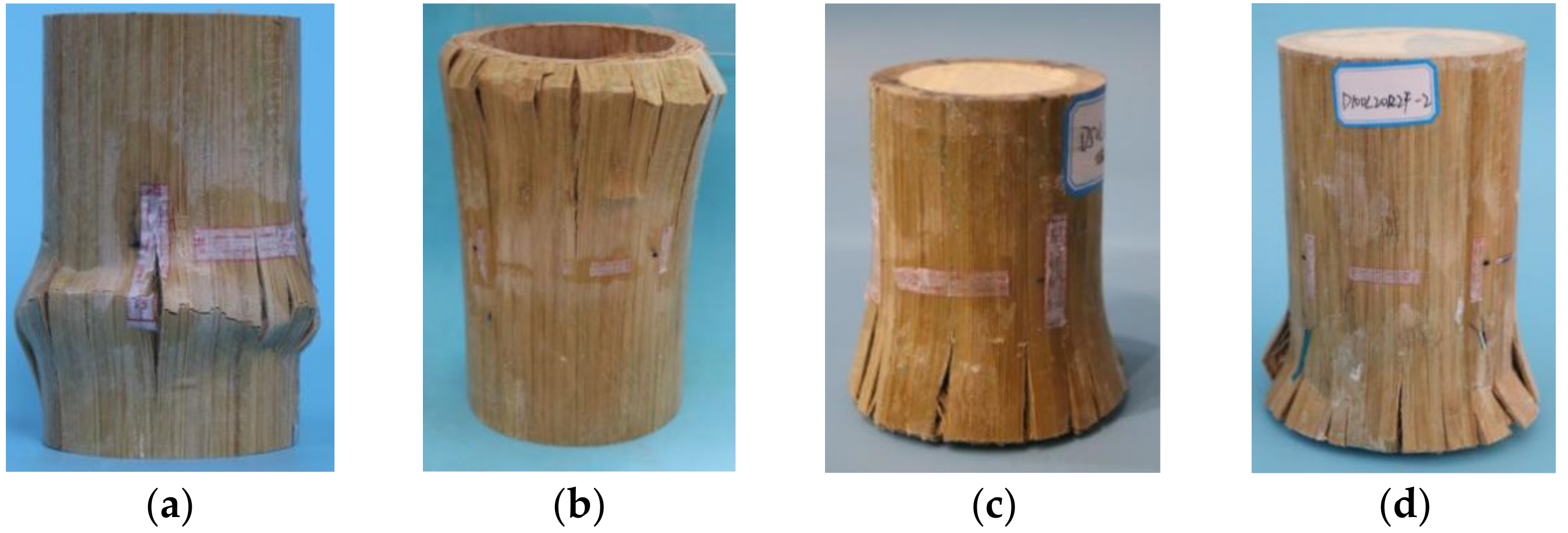
4.1. Failure Modes
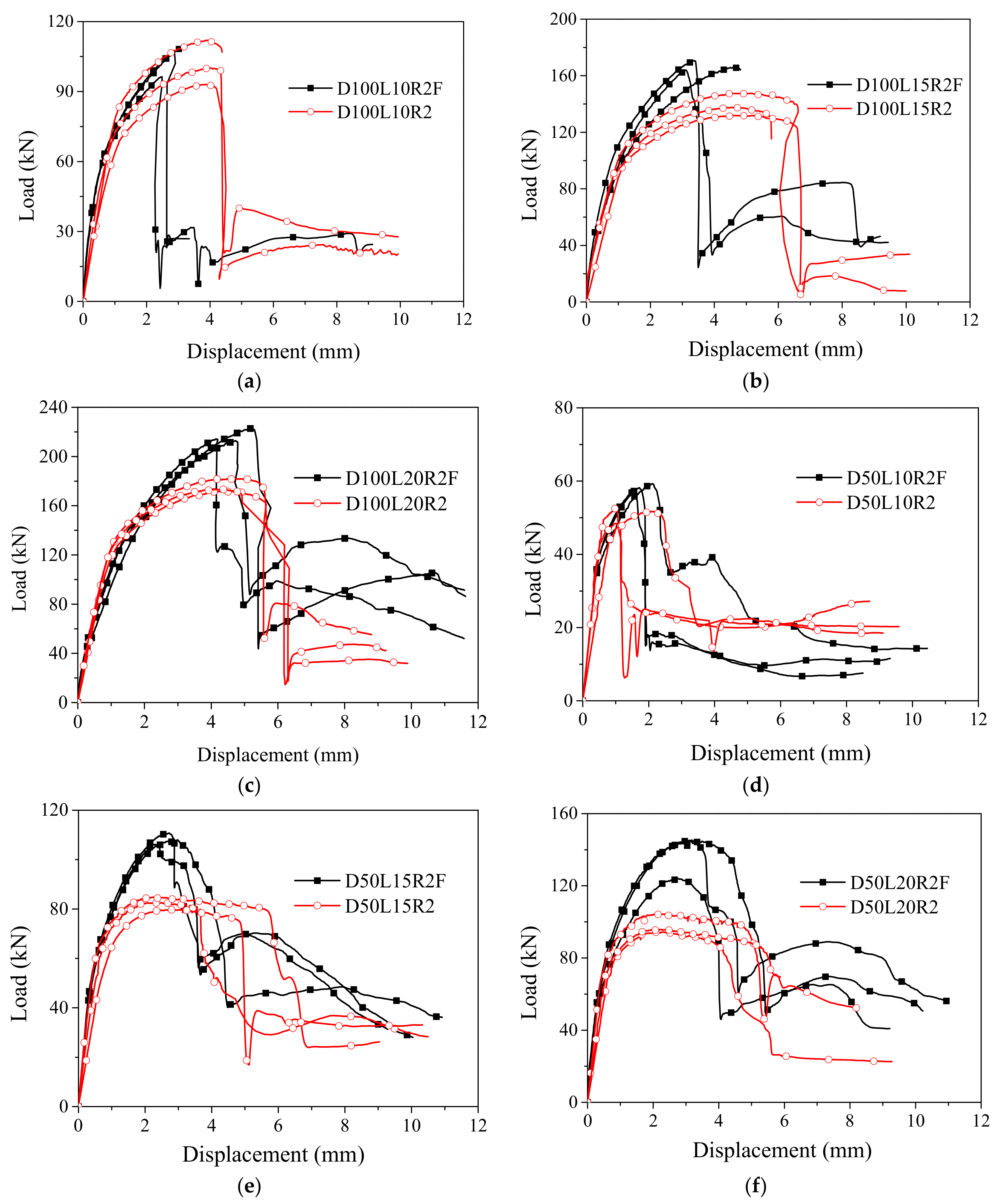
4.2. Load–Displacement Curves
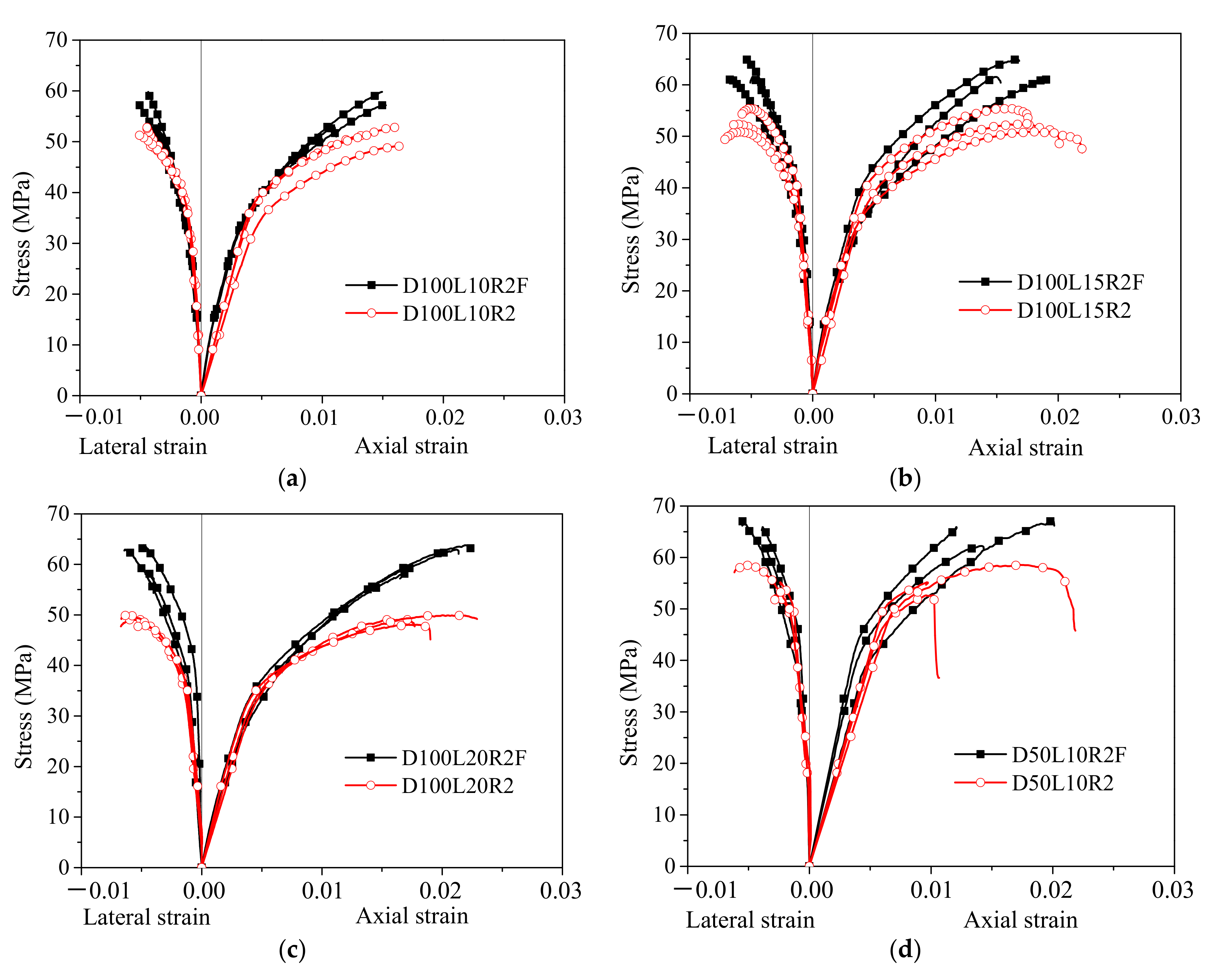
4.3. Stress–Strain Curves
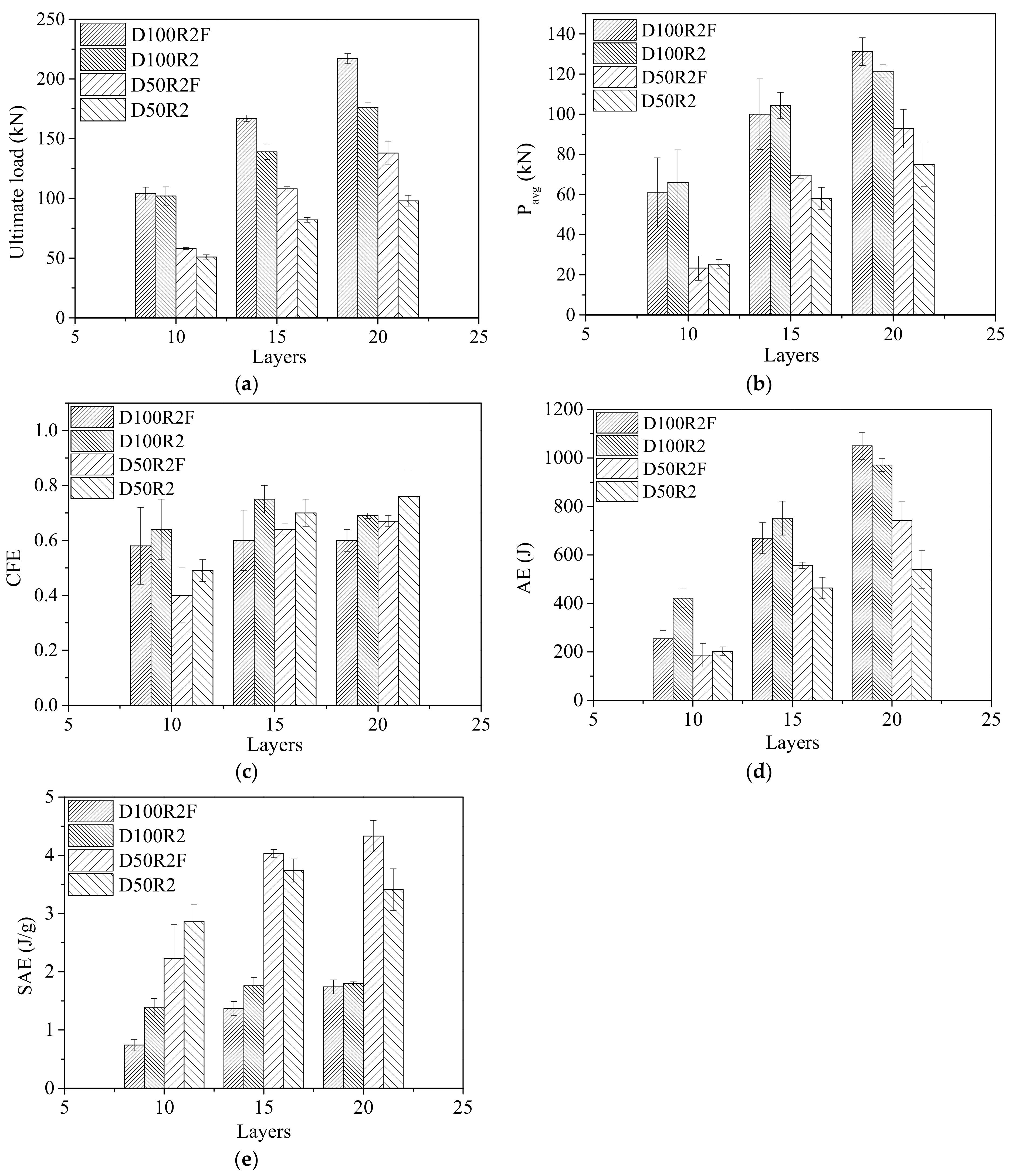
4.4. Energy Absorption Characteristics
- (1)
- The absorbed energy AE is the area under the load–displacement response curve:
- (2)
- The specific absorbed energy SAE is the absorbed energy per unit mass of the specimen:
- (3)
- The average crush load Pavg is the average load compressed to a certain displacement:
- (4)
- The crush force efficiency CFE is the ratio of the average crush load to the ultimate load:
5. Conclusions
- (1)
- The failure of polyurethane foam-filled bamboo composite tubes began with the formation of fine cracks at the ends of the tubes, and finally, the bamboo fibers were crumpled and bifurcated. There were multiple longitudinal cracks in the circumferential distribution. The failure, termed bearing failure, occurred suddenly and was classified as brittle failure. The polyurethane foam filler greatly enhanced the plastic section strengthening effect of the bamboo composite tube, and the axial peak stress was markedly improved, but it did not change the initial stiffness of the tube.
- (2)
- The energy absorption characteristics of unfilled and foam-filled bamboo composite tubes were analyzed with the following five evaluation indices: ultimate load, absorbed energy, specific absorbed energy, average crush load and crush force efficiency. Reducing the height of the bamboo composite tubes and increasing the number of winding layers of the bamboo composite tubes can effectively increase the positive effect of the foam filler on energy absorption.
- (3)
- The loading capacity of the polyurethane foam-filled bamboo composite tube was significantly higher than that of the corresponding unfilled bamboo composite tube. The bamboo composite tube was the main contributor to the load-carrying capacity of the foam-filled bamboo composite tube, and it also played a role in restraining the lateral deformation of the inner polyurethane foam and restraining its recovery. The polyurethane foam significantly improved the structural stability of the bamboo composite tube. Both of them had good complementarity in performance. The combination effect highlights the concept of the “1 + 1 > 2” combination. This research fully confirms the rationality and feasibility of the combination of bamboo composite tubes and polyurethane foam.
Author Contributions
Funding
Institutional Review Board Statement
Informed Consent Statement
Data Availability Statement
Conflicts of Interest
References
- Gatto, M.P.A.; Montrasio, L.; Zavatto, L. Experimental Analysis and Theoretical Modelling of Polyurethane Effects on 1D Wave Propagation through Sand-Polyurethane Specimens. J. Earthq. Eng. 2021, 1–24. [Google Scholar] [CrossRef]
- Gatto, M.P.A.; Montrasio, L.; Berardengo, M.; Vanali, M. Experimental Analysis of the Effects of a Polyurethane Foam on Geotechnical Seismic Isolation. J. Earthq. Eng. 2020, 26, 2948–2969. [Google Scholar] [CrossRef]
- Montrasio, L.; Gatto, M.P.A. Experimental analyses on cellular polymers for geotechnical applications. Procedia Eng. 2016, 158, 272–277. [Google Scholar] [CrossRef] [Green Version]
- Hu, D.Y.; Wang, Y.Z.; Song, B.; Wang, Y.F. Energy absorption characteristics of a foam-filled tri-tube under axial quasi-static loading: Experiment and numerical simulation. Int. J. Crashworthiness 2018, 23, 417–432. [Google Scholar] [CrossRef]
- Zhang, J.X.; Ye, Y.; Yuan, H.; Qin, Q.H.; Wang, T.J. A theoretical study of low-velocity impact of metal foam-filled circular tubes. Thin Wall Struct. 2020, 148, 106525. [Google Scholar] [CrossRef]
- Zhang, B.Y.; Wang, L.; Zhang, J.; Jiang, Y.X.; Wang, W.; Wu, G.H. Deformation and energy absorption properties of cenosphere/aluminum syntactic foam-filled circular tubes under lateral quasi-static compression. Int. J. Mech. Sci. 2021, 192, 106126. [Google Scholar] [CrossRef]
- Li, S.F.; Guo, X.; Liao, J.P.; Li, Q.; Sun, G.Y. Crushing analysis and design optimization for foam-filled aluminum/CFRP hybrid tube against transverse impact. Compos. Part B-Eng. 2020, 196, 108029. [Google Scholar] [CrossRef]
- Duarte, I.; Krstulović-Opara, L.; Dias-de-Oliveira, J.; Vesenjak, M. Axial crush performance of polymer-aluminium alloy hybrid foam filled tubes. Thin Wall Struct. 2019, 138, 124–136. [Google Scholar] [CrossRef]
- Li, Z.; Chen, R.; Lu, F. Comparative analysis of crashworthiness of empty and foam-filled thin-walled tubes. Thin Wall Struct. 2018, 124, 343–349. [Google Scholar] [CrossRef]
- Dong, C.S. Review of natural fibre-reinforced hybrid composites. J. Reinf. Plast. Comp. 2018, 37, 331–348. [Google Scholar] [CrossRef] [Green Version]
- Alkbir, M.F.M.; Sapuan, S.M.; Nuraini, A.A.; Ishak, M.R. Fibre properties and crashworthiness parameters of natural fibre-reinforced composite structure: A literature review. Compos. Struct. 2016, 148, 59–73. [Google Scholar] [CrossRef]
- Eshkoor, R.A.; Oshkovr, S.A.; Sulong, A.B.; Zulkifli, R.; Ariffin, A.K.; Azhari, C.H. Comparative research on the crashworthiness characteristics of woven natural silk/epoxy composite tubes. Mater. Des. 2013, 47, 248–257. [Google Scholar] [CrossRef]
- Eshkoor, R.A.; Ude, A.U.; Sulong, A.B.; Zulkifli, R.; Ariffin, A.K.; Azhari, C.H. Energy absorption and load carrying capability of woven natural silk epoxy–triggered composite tubes. Compos. Part B-Eng. 2015, 77, 10–18. [Google Scholar] [CrossRef]
- Oshkovr, S.A.; Eshkoor, R.A.; Taher, S.T.; Ariffin, A.K.; Azhari, C.H. Crashworthiness characteristics investigation of silk/epoxy composite square tubes. Compos. Struct. 2012, 94, 2337–2342. [Google Scholar] [CrossRef] [Green Version]
- Yan, L.; Chouw, N.; Jayaraman, K. Effect of triggering and polyurethane foam-filler on axial crushing of natural flax/epoxy composite tubes. Mater. Des. 2014, 56, 528–541. [Google Scholar] [CrossRef]
- Yan, L.; Chouw, N. Crashworthiness characteristics of flax fibre reinforced epoxy tubes for energy absorption application. Mater. Des. 2013, 51, 629–640. [Google Scholar] [CrossRef]
- Yan, L.B.; Chouw, N.; Jayaraman, K. Lateral crushing of empty and polyurethane-foam filled natural flax fabric reinforced epoxy composite tubes. Compos. Part B-Eng. 2014, 63, 15–26. [Google Scholar] [CrossRef]
- Yan, L.B.; Wang, B.; Kasal, B. Can Plant-Based Natural Fax Replace Basalt and E-Glass for Fiber-Reinforced Polymer Tubular Energy Absorbers? A Comparative Study on Quasi-Static Axial Crushing. Front. Mater. 2017, 4, 42. [Google Scholar]
- Laban, O.; Mahdi, E. Energy absorption capability of cotton fiber/epoxy composite square and rectangular tubes. J. Nat. Fibers 2016, 13, 726–736. [Google Scholar]
- Mahdi, E.; Ochoa, D.; Vazir, A.; Eltai, E. Energy absorption capability of date palm leaf fiber reinforced epoxy composites rectangular tubes. Compos. Struct. 2019, 224, 111004. [Google Scholar] [CrossRef]
- Zhou, J.; Guan, Z.; Cantwell, W.J. The energy-absorbing behaviour of composite tube-reinforced foams. Compos. Part B-Eng. 2018, 139, 227–237. [Google Scholar] [CrossRef]
- Liu, Z.; Huang, Z.; Qin, Q. Experimental and theoretical investigations on lateral crushing of aluminum foam-filled circular tubes. Compos. Struct. 2017, 175, 19–27. [Google Scholar] [CrossRef]
- Elahi, S.A.; Rouzegar, J.; Niknejad, A.; Assaee, H. Theoretical study of absorbed energy by empty and foam-filled composite tubes under lateral compression. Thin Wall Struct. 2017, 114, 1–10. [Google Scholar] [CrossRef]
- Wei, Y.; Tang, S.; Ji, X.; Zhao, K.; Li, G. Stress-strain behavior and model of bamboo scrimber under cyclic axial compression. Eng. Struct. 2020, 209, 110279. [Google Scholar] [CrossRef]
- Chen, S.; Wei, Y.; Hu, Y.; Zhai, Z.; Wang, L. Behavior and strength of rectangular bamboo scrimber columns with shape and slenderness effects. Mater. Today Commun. 2020, 25, 101392. [Google Scholar] [CrossRef]
- Wei, Y.; Zhou, M.Q.; Zhao, K.P.; Zhao, K.; Li, G.F. Stress-strain relationship model of glulam bamboo under axial loading. Adv. Compos. Lett. 2020, 29, 1–11. [Google Scholar] [CrossRef]
- Wei, Y.; Zhao, K.P.; Hang, C.; Chen, S.; Ding, M.M. Experimental study on the creep behavior of recombinant bamboo. J. Renew. Mater. 2020, 8, 251–273. [Google Scholar] [CrossRef]
- Xiao, Y.; Chen, G.; Feng, L. Experimental studies on roof trusses made of glubam. Mater. Struct 2014, 47, 1879–1890. [Google Scholar] [CrossRef]
- Xiao, Y.; Zhou, Q.; Shan, B. Design and construction of modern bamboo bridges. J. Bridg. Eng. 2010, 15, 533–541. [Google Scholar] [CrossRef]
- Huang, Z.; Sun, Y.; Musso, F. Assessment of bamboo application in building envelope by comparison with reference timber. Constr. Build. Mater. 2017, 156, 844–860. [Google Scholar] [CrossRef]
- Xu, M.; Cui, Z.; Tu, L.; Xia, Q.; Chen, Z. The effect of elevated temperatures on the mechanical properties of laminated bamboo. Constr. Build. Mater. 2019, 226, 32–43. [Google Scholar] [CrossRef]
- Nie, Y.H.; Wei, Y.; Huang, L.J.; Liu, Y.; Dong, F.H. Influence of slenderness ratio and sectional geometry on the axial compression behavior of original bamboo columns. J. Wood Sci. 2021, 67, 36. [Google Scholar] [CrossRef]
- Huang, X.D.; Shupe, T.F.; Hse, C.Y. Study of moso bamboo’s permeability and mechanical properties. Emerg. Mater. Res. 2015, 4, 130–138. [Google Scholar] [CrossRef]
- Nie, Y.; Wei, Y.; Miao, K.; Zhao, K.; Huang, L. Experimental investigation of full-culm bamboo tubes strengthened by filled concrete and bamboo sheets under axial compression. J. Build. Eng. 2022, 45, 103548. [Google Scholar] [CrossRef]
- Umer, R.; Balawi, S.; Raja, P.; Cantwell, W.J. The energy-absorbing characteristics of polymer foams reinforced with bamboo tubes. J. Sandw. Struct. Mater. 2014, 16, 108–122. [Google Scholar] [CrossRef]
- Zou, M.; Wei, C.G.; Li, J.Q.; Xu, S.C.; Zhang, X. The energy absorption of bamboo under dynamic axial loading. Thin Wall Struct. 2015, 95, 255–261. [Google Scholar]
- Wang, Z.; Wei, Y.; Hu, Y.; Chen, S.; Zhao, K. An investigation of the flexural performance of bamboo-concrete composite beams with precast light concrete slabs and dowel connectors. J. Build. Eng. 2021, 41, 102759. [Google Scholar] [CrossRef]
- Wang, Z.; Wei, Y.; Li, N.; Zhao, K.; Ding, M. Flexural behavior of bamboo–concrete composite beams with perforated steel plate connections. J. Wood Sci. 2020, 66, 4. [Google Scholar] [CrossRef] [Green Version]
- Wei, Y.; Chen, S.; Jiang, J.; Zhou, M.; Zhao, K. Experimental investigation of bamboo-concrete composite beams with threaded reinforcement connections. J. Sandw Struct. Mater. 2022, 24, 601–626. [Google Scholar] [CrossRef]
- Wei, Y.; Ji, X.W.; Duan, M.J.; Li, G.F. Flexural performance of bamboo scrimber beams strengthened with fiber-reinforced polymer. Constr Build. Mater. 2017, 142, 66–82. [Google Scholar] [CrossRef]
- Wei, Y.; Yan, S.; Zhao, K.; Dong, F.; Li, G. Experimental and theoretical investigation of steel-reinforced bamboo scrimber beams. Eng. Struct. 2020, 223, 111179. [Google Scholar] [CrossRef]
- Tian, L.M.; Kou, Y.F.; Hao, J.P. Flexural behavior of sprayed lightweight composite mortar-original bamboo composite beams: Experimental study. BioResources 2019, 14, 500–517. [Google Scholar]
- Tian, L.; Kou, Y.; Hao, J. Axial compressive behaviour of sprayed composite mortar–original bamboo composite columns. Constr. Build. Mater. 2019, 215, 726–736. [Google Scholar] [CrossRef]
- Nie, Y.H.; Wei, Y.; Zhao, K.; Ding, M.M.; Huang, L.J. Compressive performance of bamboo sheet twining tube-confined recycled aggregate concrete columns. Constr. Build. Mater. 2022, 323, 126544. [Google Scholar] [CrossRef]
- Cheng, X.Y.; Wei, Y.; Nie, Y.H.; Wang, G.F.; Li, G.F. Compressive behavior of bamboo sheet twining tube-confined concrete columns. Polymers 2021, 13, 4124. [Google Scholar] [CrossRef]
- Kou, Y.F.; Tian, L.M.; Jin, B.B. Axial compressive behavior of bamboo slices twining tube-confined concrete. Eur. J. Wood Wood Prod. 2022, 80, 115–129. [Google Scholar] [CrossRef]
- Gatto, M.P.A.; Montrasio, L. Analysis of the Behaviour of Very Slender Piles: Focus on the Ultimate Load. Int. J. Civ. Eng. 2021, 19, 145–153. [Google Scholar] [CrossRef]


| Group | Mechanical Indices | Average | Coefficient of Variation | Failure Mode |
|---|---|---|---|---|
| t = 5 mm (Compression) | Ultimate strength (MPa) | 55.40 | 5.40% | 1S9L |
| Elastic limit stress (MPa) | 38.47 | 10.81% | ||
| t = 7.5 mm (Compression) | Ultimate strength (MPa) | 59.73 | 4.03% | 2S8L |
| Elastic limit stress (MPa) | 39.33 | 9.89% | ||
| t = 10 mm (Compression) | Ultimate strength (MPa) | 54.29 | 7.98% | 4S6L |
| Elastic limit stress (MPa) | 40.40 | 13.00% | ||
| t = 0.5 mm (Tension) | Ultimate strength (MPa) | 95.03 | 5.10% | Serrated failure |
| Ultimate strain | 0.0077 | 3.74% | ||
| Modulus of elasticity (GPa) | 12.12 | 6.79% |
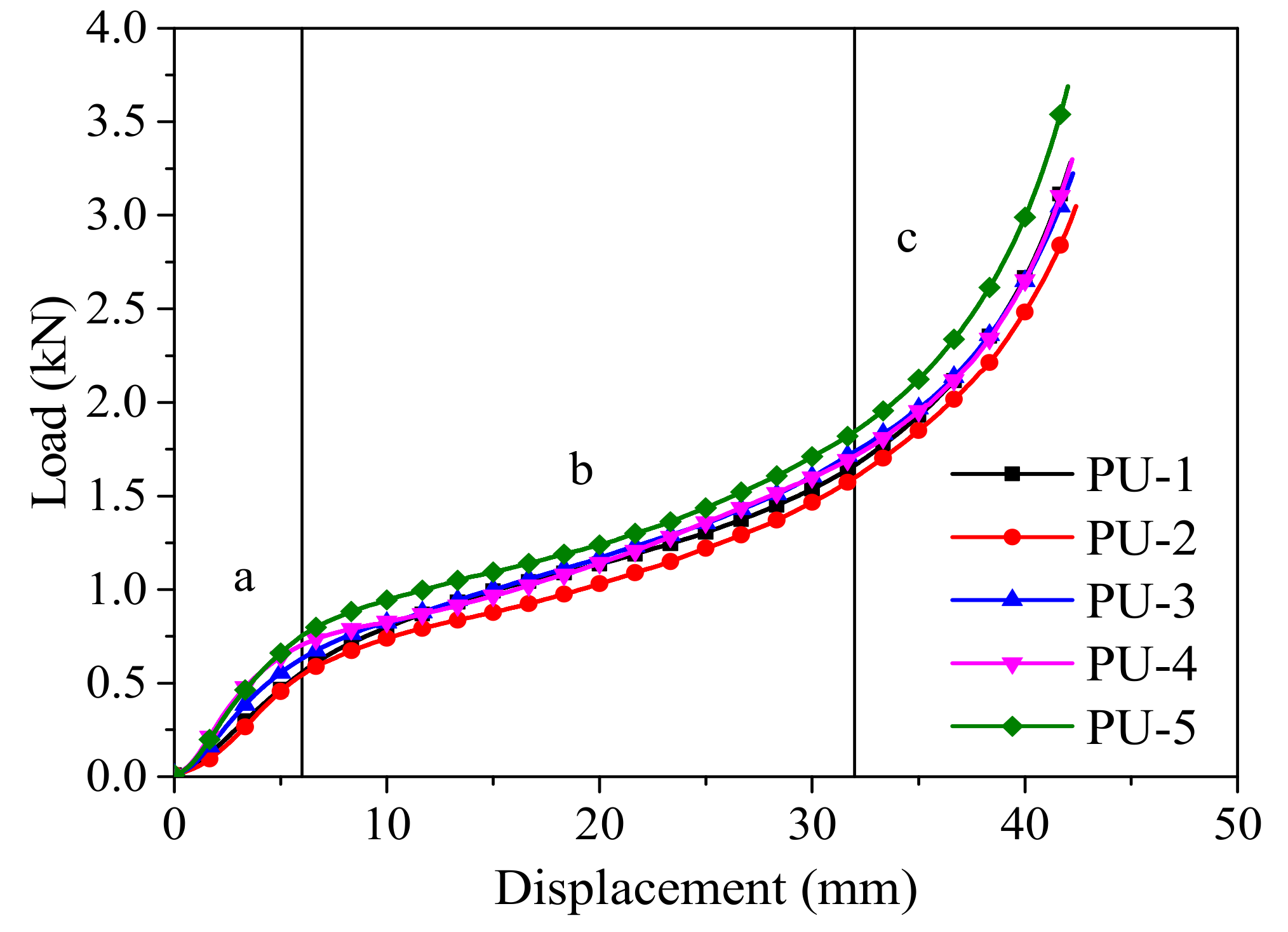
| Specimen | Load Fpu (N) | Density ρ (kg·m−3) | Stress σ10 (kPa) | Nominal Modulus of Elasticity E (kPa) |
|---|---|---|---|---|
| PU-1 | 3230 | 29.94 | 51 | 526 |
| PU-2 | 2928 | 31.96 | 55 | 588 |
| PU-3 | 3144 | 31.70 | 59 | 663 |
| PU-4 | 3218 | 30.66 | 67 | 861 |
| PU-5 | 3678 | 33.24 | 71 | 842 |
| Average | 3240 | 31.50 | 60 | 696 |
| Variation | 8.44% | 4.02% | 13.38% | 21.61% |
| Group | Specimen | Length H (mm) | Diameter D (mm) | Winding layers L | Wall Thickness t (mm) | Filler |
|---|---|---|---|---|---|---|
| D50 | D50L10R2-1/2/3 | 100 | 50 | 10 | 5 | N/A |
| D50L15R2-1/2/3 | 100 | 50 | 15 | 7.5 | N/A | |
| D50L20R2-1/2/3 | 100 | 50 | 20 | 10 | N/A | |
| D100 | D100L10R2-1/2/3 | 200 | 100 | 10 | 5 | N/A |
| D100L15R2-1/2/3 | 200 | 100 | 15 | 7.5 | N/A | |
| D100L20R2-1/2/3 | 200 | 100 | 20 | 10 | N/A | |
| D50F | D50L10R2F-1/2/3 | 100 | 50 | 10 | 5 | Foam |
| D50L15R2F-1/2/3 | 100 | 50 | 15 | 7.5 | Foam | |
| D50L20R2F-1/2/3 | 100 | 50 | 20 | 10 | Foam | |
| D100F | D100L10R2F-1/2/3 | 200 | 100 | 10 | 5 | Foam |
| D100L15R2F-1/2/3 | 200 | 100 | 15 | 7.5 | Foam | |
| D100L20R2F-1/2/3 | 200 | 100 | 20 | 10 | Foam |
| Group | Specimen | Ultimate Load Pmax (kN) | Peak Stress σp (MPa) | Peak Strain εp | Ultimate Stress σcu (MPa) | Ultimate Strain εcu | Modulus of Elasticity E (MPa) |
|---|---|---|---|---|---|---|---|
| D50 | D50L10R2-1 | 53.0 | 55.27 | 0.0097 | 55.27 | 0.0097 | 8300 |
| D50L10R2-2 | 48.6 | 52.78 | 0.0102 | 51.76 | 0.0103 | 8000 | |
| D50L10R2-3 | 51.8 | 58.68 | 0.0172 | 57.70 | 0.0200 | 7400 | |
| D50L15R2-1 | 82.7 | 53.66 | 0.0156 | 50.14 | 0.0189 | 8300 | |
| D50L15R2-2 | 79.8 | 52.93 | 0.0219 | 49.61 | 0.0325 | 7300 | |
| D50L15R2-3 | 84.8 | 55.48 | 0.0131 | 50.28 | 0.0209 | 10,800 | |
| D50L20R2-1 | 94.4 | 47.84 | 0.0166 | 43.66 | 0.0229 | 8500 | |
| D50L20R2-2 | 104.5 | 54.17 | 0.0166 | 50.99 | 0.0237 | 9400 | |
| D50L20R2-3 | 95.8 | 50.82 | 0.0150 | 46.12 | 0.0283 | 9600 | |
| D100 | D100L10R2-1 | 93.1 | 49.19 | 0.0164 | 48.55 | 0.0164 | 7800 |
| D100L10R2-2 | 100.3 | 52.99 | 0.0158 | 52.46 | 0.0161 | 9300 | |
| D100L10R2-3 | 111.9 | 51.45 | 0.0140 | 50.38 | 0.0146 | 9400 | |
| D100L15R2-1 | 137.6 | 52.38 | 0.0168 | 51.27 | 0.0193 | 9400 | |
| D100L15R2-2 | 132.0 | 50.95 | 0.0175 | 47.79 | 0.0219 | 9700 | |
| D100L15R2-3 | 147.7 | 55.46 | 0.0160 | 52.44 | 0.0175 | 10,000 | |
| D100L20R2-1 | 171.8 | 49.18 | 0.0159 | 47.16 | 0.0176 | 7700 | |
| D100L20R2-2 | 182.2 | 49.99 | 0.0201 | 49.20 | 0.0229 | 8400 | |
| D100L20R2-3 | 173.6 | 48.13 | 0.0179 | 47.35 | 0.0189 | 9300 | |
| D50F | D50L10R2F-1 | 58.3 | 66.04 | 0.0121 | 66.04 | 0.0121 | 11,400 |
| D50L10R2F-2 | 59.4 | 67.28 | 0.0201 | 67.28 | 0.0201 | 8500 | |
| D50L10R2F-3 | 57.4 | 62.34 | 0.0138 | 62.34 | 0.0138 | 10,500 | |
| D50L15R2F-1 | 106.5 | 73.06 | 0.0215 | 73.06 | 0.0215 | 9300 | |
| D50L15R2F-2 | 108.1 | 73.12 | 0.0282 | 73.12 | 0.0282 | 12,300 | |
| D50L15R2F-3 | 110.8 | 76.01 | 0.0258 | 76.01 | 0.0258 | 10,100 | |
| D50L20R2F-1 | 145.1 | 71.90 | 0.0288 | 71.05 | 0.0297 | 8000 | |
| D50L20R2F-2 | 124.3 | 62.99 | 0.0266 | 61.90 | 0.0285 | 7900 | |
| D50L20R2F-3 | 145.5 | 72.91 | 0.0315 | 67.47 | 0.0400 | 8000 | |
| D100F | D100L10R2F-1 | 107.1 | 59.90 | 0.0149 | 59.90 | 0.0149 | 8800 |
| D100L10R2F-2 | 96.8 | 53.10 | 0.0109 | 53.10 | 0.0109 | 9300 | |
| D100L10R2F-3 | 108.9 | 57.53 | 0.0151 | 57.53 | 0.0151 | 9300 | |
| D100L15R2F-1 | 165.9 | 61.12 | 0.0191 | 61.12 | 0.0191 | 8600 | |
| D100L15R2F-2 | 164.0 | 61.58 | 0.0149 | 61.58 | 0.0149 | 8500 | |
| D100L15R2F-3 | 170.7 | 64.98 | 0.0166 | 64.98 | 0.0166 | 10,100 | |
| D100L20R2F-1 | 223.0 | 63.83 | 0.0223 | 63.83 | 0.0223 | 6500 | |
| D100L20R2F-2 | 214.7 | 58.29 | 0.0167 | 58.29 | 0.0167 | 6900 | |
| D100L20R2F-3 | 213.1 | 63.04 | 0.0209 | 63.04 | 0.0209 | 8600 |
| Group | Specimen | Mass m (g) | Wall Thickness t (mm) | Ultimate Load Pmax (kN) | Absorbed Energy AE (J) | Specific Absorbed Energy SAE (J/g) | Average Crush Load Pavg (kN) | Crush Force Efficiency CFE |
|---|---|---|---|---|---|---|---|---|
| D100F | D100L10R2F-1 | 342.3 | 5.4 | 107.1 | 219.7 | 0.64 | 65.68 | 0.61 |
| D100L10R2F-2 | 341.9 | 5.5 | 96.8 | 299.1 | 0.87 | 37.39 | 0.39 | |
| D100L10R2F-3 | 345.3 | 5.7 | 108.9 | 243.5 | 0.71 | 79.42 | 0.73 | |
| D100L15R2F-1 | 463.1 | 8.0 | 165.9 | 597.2 | 1.29 | 123.87 | 0.75 | |
| D100L15R2F-2 | 513.2 | 7.9 | 164 | 656.4 | 1.28 | 82.05 | 0.50 | |
| D100L15R2F-3 | 485.0 | 7.8 | 170.7 | 753.1 | 1.55 | 94.14 | 0.55 | |
| D100L20R2F-1 | 601.3 | 10.1 | 223 | 1041.6 | 1.73 | 130.20 | 0.58 | |
| D100L20R2F-2 | 615.7 | 10.6 | 214.7 | 986.2 | 1.60 | 123.28 | 0.57 | |
| D100L20R2F-3 | 589.7 | 9.8 | 213.1 | 1121.3 | 1.90 | 140.16 | 0.66 | |
| D100 | D100L10R2-1 | 287.2 | 5.7 | 93.1 | 403.8 | 1.41 | 50.48 | 0.54 |
| D100L10R2-2 | 303.3 | 5.7 | 100.3 | 474.1 | 1.56 | 59.26 | 0.59 | |
| D100L10R2-3 | 322.3 | 6.5 | 111.9 | 387.6 | 1.20 | 88.43 | 0.79 | |
| D100L15R2-1 | 418.0 | 7.8 | 137.6 | 654.1 | 1.56 | 112.98 | 0.82 | |
| D100L15R2-2 | 423.2 | 7.7 | 132.0 | 783.1 | 1.85 | 97.89 | 0.74 | |
| D100L15R2-3 | 434.4 | 7.9 | 147.7 | 817 | 1.88 | 102.13 | 0.69 | |
| D100L20R2-1 | 527.7 | 10.1 | 171.8 | 961.9 | 1.82 | 120.24 | 0.70 | |
| D100L20R2-2 | 556.2 | 10.5 | 182.2 | 1006.6 | 1.81 | 125.83 | 0.69 | |
| D100L20R2-3 | 536.4 | 10.4 | 173.6 | 944.1 | 1.76 | 118.01 | 0.68 | |
| D50F | D50L10R2F-1 | 84.1 | 5.1 | 58.3 | 156.5 | 1.86 | 19.56 | 0.34 |
| D50L10R2F-2 | 83.8 | 5.1 | 59.4 | 255.5 | 3.05 | 31.94 | 0.54 | |
| D50L10R2F-3 | 82.3 | 5.3 | 57.4 | 147.7 | 1.79 | 18.46 | 0.32 | |
| D50L15R2F-1 | 139.4 | 8.0 | 106.5 | 561.7 | 4.03 | 70.21 | 0.66 | |
| D50L15R2F-2 | 137.0 | 8.1 | 108.1 | 539.5 | 3.94 | 67.44 | 0.62 | |
| D50L15R2F-3 | 138.7 | 8.0 | 110.8 | 570 | 4.11 | 71.25 | 0.64 | |
| D50L20R2F-1 | 178.4 | 10.6 | 145.1 | 794.6 | 4.45 | 99.33 | 0.68 | |
| D50L20R2F-2 | 160.6 | 10.4 | 124.3 | 634.1 | 3.95 | 79.26 | 0.64 | |
| D50L20R2F-3 | 174.2 | 10.5 | 145.5 | 799.5 | 4.59 | 99.94 | 0.69 | |
| D50 | D50L10R2-1 | 74.2 | 5.5 | 53.0 | 196.6 | 2.65 | 24.58 | 0.46 |
| D50L10R2-2 | 69.8 | 5.3 | 48.6 | 184.1 | 2.64 | 23.01 | 0.47 | |
| D50L10R2-3 | 69.2 | 5.1 | 51.8 | 227.1 | 3.28 | 28.39 | 0.55 | |
| D50L15R2-1 | 121.3 | 8.4 | 82.7 | 422.4 | 3.48 | 52.80 | 0.64 | |
| D50L15R2-2 | 117.4 | 8.2 | 79.8 | 443.9 | 3.78 | 55.49 | 0.70 | |
| D50L15R2-3 | 132.0 | 8.3 | 84.8 | 524.4 | 3.97 | 65.55 | 0.77 | |
| D50L20R2-1 | 151.8 | 10.4 | 94.4 | 474.9 | 3.13 | 59.36 | 0.63 | |
| D50L20R2-2 | 165.9 | 10.2 | 104.5 | 650.9 | 3.92 | 81.36 | 0.78 | |
| D50L20R2-3 | 155.7 | 10.0 | 95.8 | 495.9 | 3.18 | 84.37 | 0.88 |
Publisher’s Note: MDPI stays neutral with regard to jurisdictional claims in published maps and institutional affiliations. |
© 2022 by the authors. Licensee MDPI, Basel, Switzerland. This article is an open access article distributed under the terms and conditions of the Creative Commons Attribution (CC BY) license (https://creativecommons.org/licenses/by/4.0/).
Share and Cite
Wei, Y.; Tang, S.; Chen, S.; Wang, Q.; Wang, J. Mechanical Behavior of Foam-Filled Bamboo Composite Tubes under Axial Compression. Polymers 2022, 14, 2006. https://doi.org/10.3390/polym14102006
Wei Y, Tang S, Chen S, Wang Q, Wang J. Mechanical Behavior of Foam-Filled Bamboo Composite Tubes under Axial Compression. Polymers. 2022; 14(10):2006. https://doi.org/10.3390/polym14102006
Chicago/Turabian StyleWei, Yang, Shuaifeng Tang, Si Chen, Qiudong Wang, and Jiaqing Wang. 2022. "Mechanical Behavior of Foam-Filled Bamboo Composite Tubes under Axial Compression" Polymers 14, no. 10: 2006. https://doi.org/10.3390/polym14102006
APA StyleWei, Y., Tang, S., Chen, S., Wang, Q., & Wang, J. (2022). Mechanical Behavior of Foam-Filled Bamboo Composite Tubes under Axial Compression. Polymers, 14(10), 2006. https://doi.org/10.3390/polym14102006