
A Water-Soluble Core for Manufacturing Hollow Injection-Molded Products


Abstract
:1. Introduction
2. Fabrication Process and Product Design
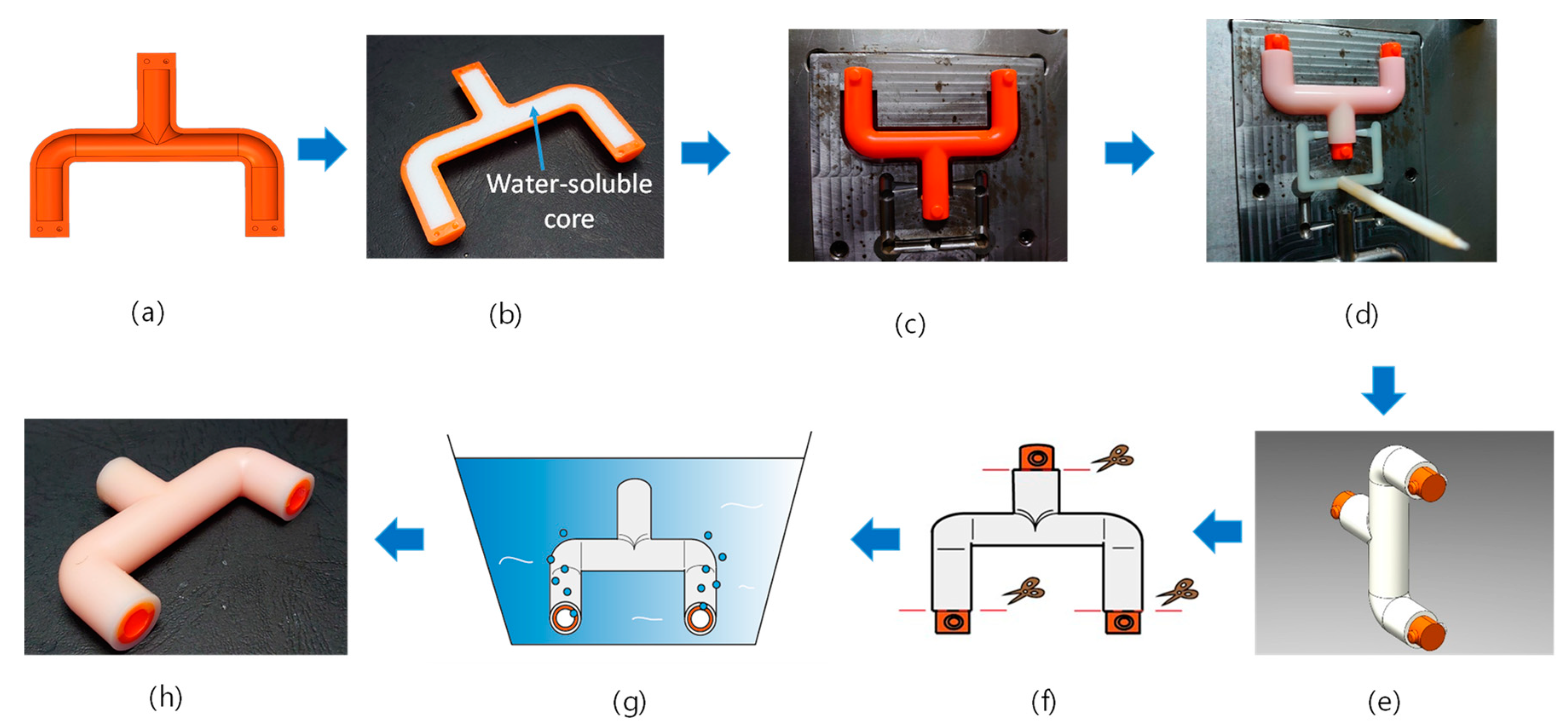
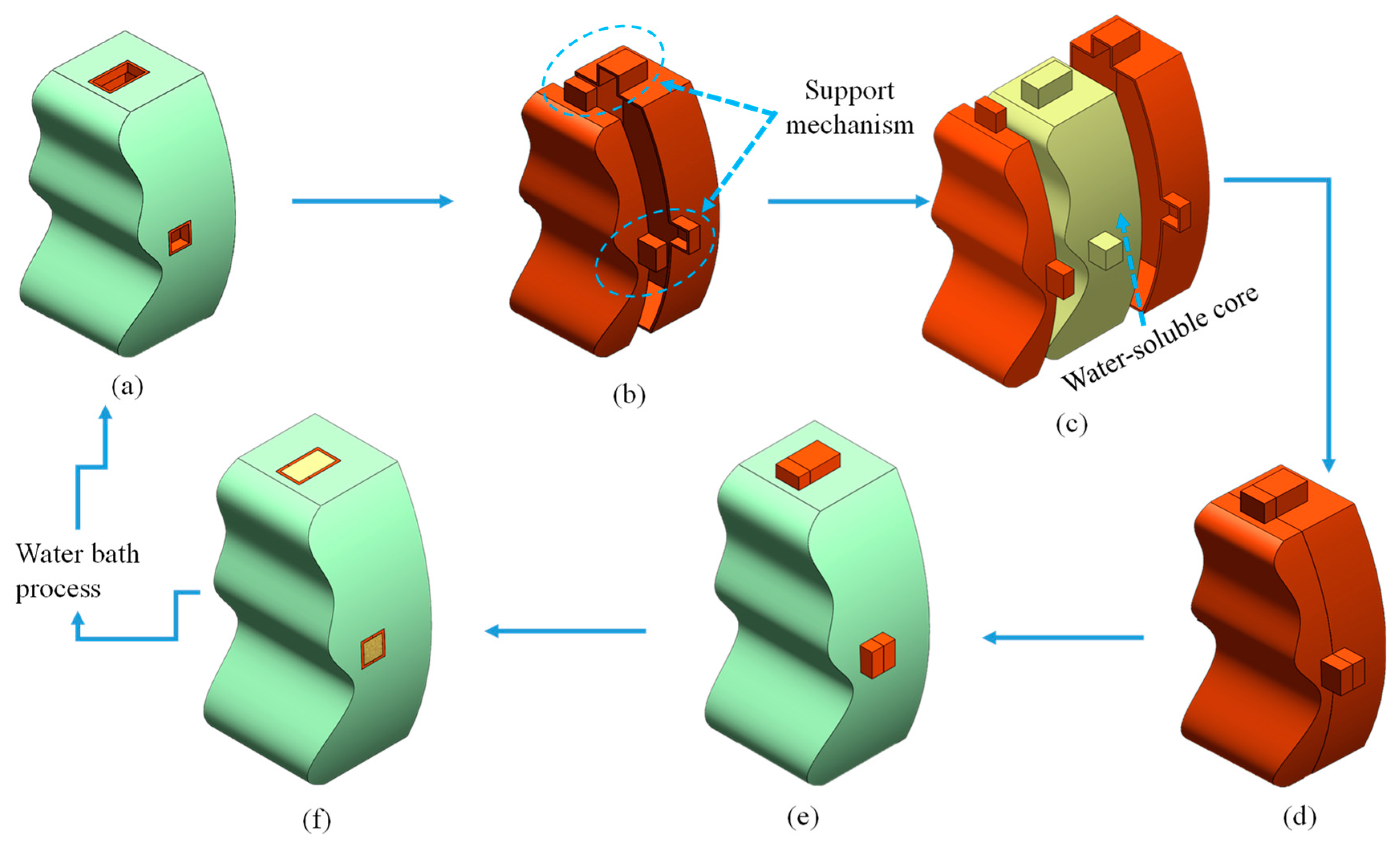
2.1. Fabrication Process
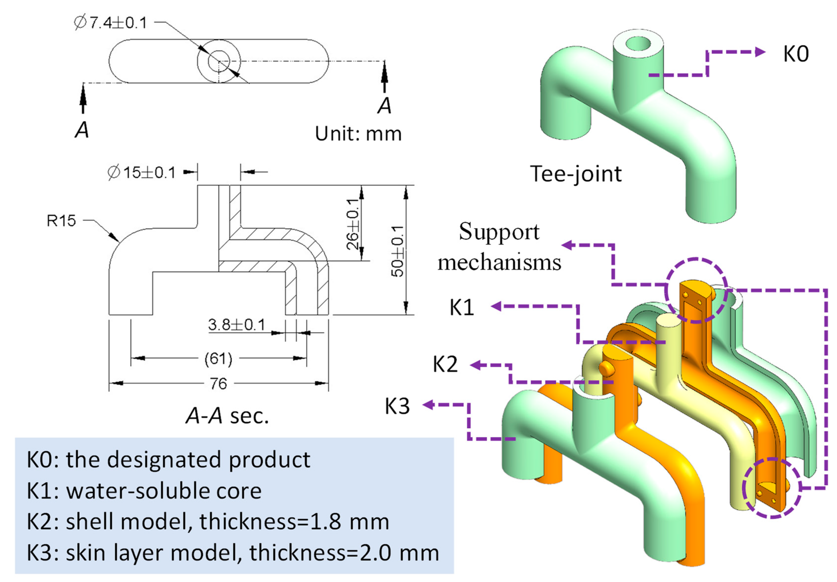
2.2. Design Guidance of the Shell Model and the Skin Layer Model of the Product
3. Water-Soluble Core Development
3.1. Design of the Experiment
3.2. Specimen Preparation and Characteristics
4. Experimental Procedure
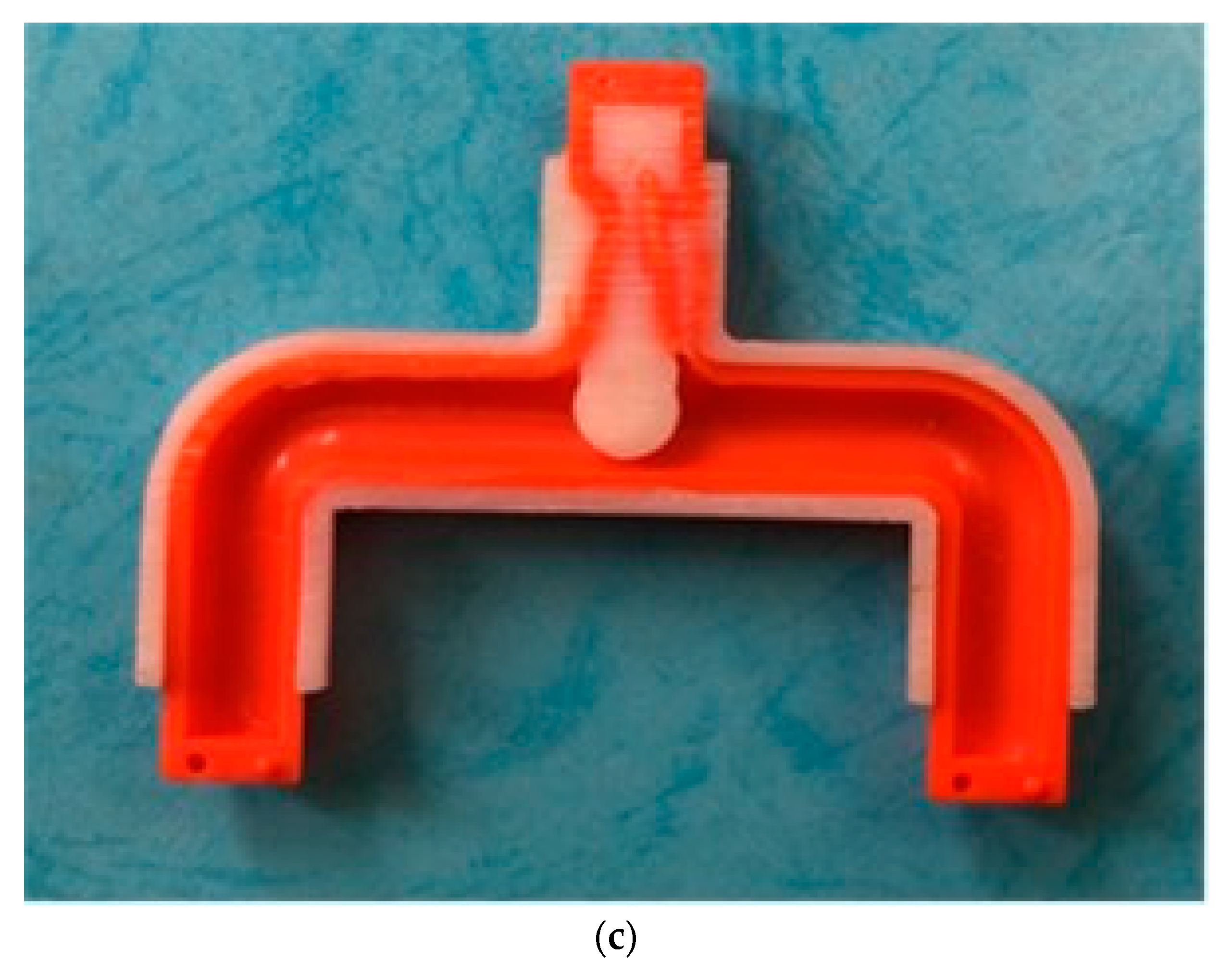
4.1. The Demonstrated Product and Its Mold Design
4.2. Materials and Injection Molding
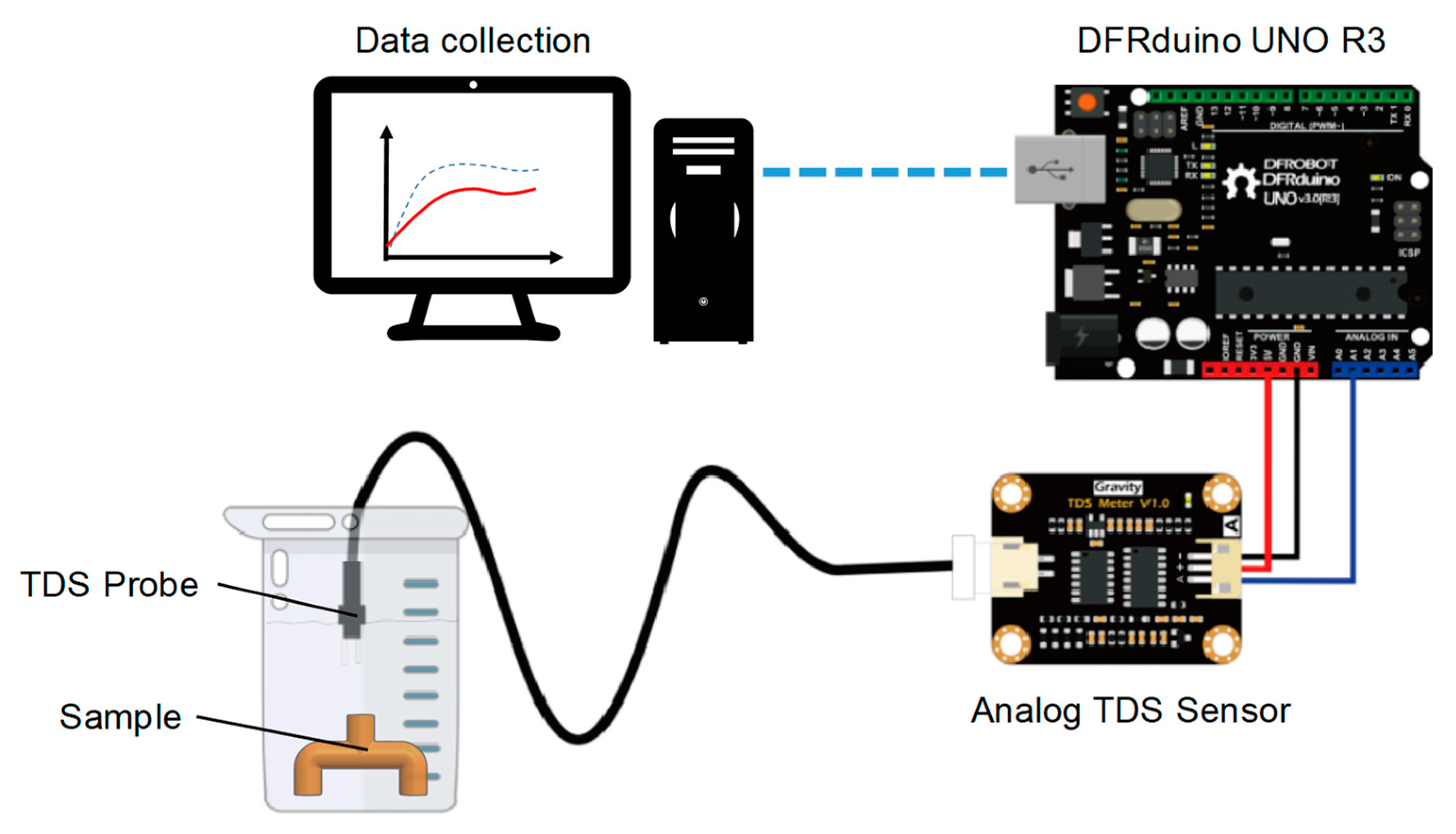
4.3. Evaluation of the Molded Product (Dimensional Measurement and Core Removal Rate)
5. Results and Discussion
5.1. Analyses of S/N and ANOVA Results
5.2. Dimensional Measurement of the Molded Product
5.3. Core Removal Rate of Water-Soluble Core
6. Conclusions
Author Contributions
Funding
Institutional Review Board Statement
Informed Consent Statement
Data Availability Statement
Conflicts of Interest
References
- Dorp, E.R.; Blume, C.; Haedecke, T.; Pata, V.; Reith, D.; Bruch, O.; Möginger, B.; Hausnerova, B. Process-dependent structural and deformation properties of extrusion blow molding parts. Polym. Test. 2019, 77, 105903. [Google Scholar] [CrossRef]
- Rodríguez-Castellanos, W.; Martínez-Bustos, F.; Rodrigue, D.; Trujillo-Barragán, M. Extrusion blow molding of a starch–gelatin polymer matrix reinforced with cellulose. Eur. Polym. J. 2015, 73, 335–343. [Google Scholar] [CrossRef]
- Mikhail Katsevman, M.; Pavlov, A.; Kruglov, P. Production of thermoplastic compound materials for processing by injection molding, blow molding and extrusion. Reinf. Plast. 2018, 62, 318–321. [Google Scholar] [CrossRef]
- Stevenson, J.F. Innovation in Polymer Processing: Molding; Carl Hanser Verlag: Munich, Germany, 1996. [Google Scholar]
- Yaagoubi, M.E.; Haas, S.; Schwegler, D. The magnetic orientation of hard ferrites rubber bonded permanent magnets using the injection moulding. Sens. Actuators A Phys. 2021, 230, 112571. [Google Scholar] [CrossRef]
- Klein, R. Laser Welding of Plastics: Materials, Processes and Industrial Applications; John Wiley & Sons: Hoboken, NJ, USA, 2012. [Google Scholar]
- Ettemeyer, F.; Schweinefuß, M.; Lechner, P.; Stahl, J.; Greß, T.; Kaindl, J.; Durach, L.; Volk, W.; Günther, D. Characterisation of the decoring behaviour of inorganically bound cast-in sand cores for light metal casting. J. Mater. Process. Technol. 2021, 296, 117201. [Google Scholar] [CrossRef]
- Kohlstädt, S.; Vynnycky, M.; Goeke, S. On the CFD Modelling of Slamming of the Metal Melt in High-Pressure Die Casting Involving Lost Cores. Metals 2021, 11, 78. [Google Scholar] [CrossRef]
- Jelínek, P.; Adámková, E. Lost cores for high-pressure die casting. Arch. Foundry Eng. 2014, 14, 101–104. [Google Scholar] [CrossRef]
- Kaerger, J.; Atz, L. Water soluble mandrels for lost core applications in manufacturing of hollow composite structures. In Proceedings of the SAMPE Europe Conference Nantes, Nantes, France, 17–19 September 2019. [Google Scholar]
- Xiao, Z.; Harper, L.T.; Kennedy, A.R.; Warrior, N.A. A water-soluble core material for manufacturing hollow composite sections. Compos. Struct. 2017, 182, 380–390. [Google Scholar] [CrossRef]
- Osswald, T.A.; Turng, L.-S.; Gramann, P. Injection Molding Handbook; Carl Hanser Verlag: Munich, Germany, 2008. [Google Scholar]
- McNulty, J.D.; Kharbas, H.; Thompson, C.; Ashton, R.S.; Turng, L.S. A method to create internal geometries within injection molded parts using water soluble Polyvinyl alcohol (PVOH) inserts. In Proceedings of the ANTEC Conference Orlando, Orlando, FL, USA, 23–25 March 2015. [Google Scholar]
- Salzmann, M.; Blößl, Y.; Todorovic, A.; Schledjewski, R. Usage of Near-Infrared Spectroscopy for Inline Monitoring the Degree of Curing in RTM Processes. Polymers 2021, 13, 3145. [Google Scholar] [CrossRef] [PubMed]
- Bhudolia, S.K.; Perrotey, P.; Gohel, G.; Joshi, S.C.; Gerard, P.; Leong, K.F. Optimizing Bladder Resin Transfer Molding Process to Manufacture Complex, Thin-Ply Thermoplastic Tubular Composite Structures: An Experimental Case Study. Polymers 2021, 13, 4093. [Google Scholar] [CrossRef]
- Bargaoui, H.; Azzouz, F.; Thibault, D.; Cailletaud, G. Thermomechanical behavior of resin bonded foundry sand cores during casting. J. Mater. Processing Technol. 2017, 246, 30–41. [Google Scholar] [CrossRef]
- Sussich, F.; Urbani, R.; Princivalle, F.; Cesàro, A. Polymorphic amorphous and crystalline forms of trehalose. J. Am. Chem. Soc. 1998, 120, 7893–7899. [Google Scholar] [CrossRef]
- Kan, Z.; Yan, X.; Ma, J. Conformation dynamics and polarization effect of α, α-Trehalose in a vacuum and in aqueous and salt solutions. J. Phys. Chem. A 2015, 119, 1573–1589. [Google Scholar] [CrossRef] [PubMed]
- Yanykin, D.V.; Khorobrykh, A.A.; Semenov, A.Y.; Mamedov, M.D. Effect of Trehalose on the Functional Properties of Photosystem II. In Allakhverdiev, Photosynthesis: Molecular Approaches to Solar Energy Conversion, Proceedings of the Advances in Photosynthesis and Respiration; Shen, J.R., Satoh, K., Eds.; Springer: Cham, Switzerland, 2021; Volume 47. [Google Scholar]


| Level 1 | Level 2 | Level 3 | |
|---|---|---|---|
| A, Binder content (wt.%) | 5 | 8 | 12 |
| B, Applied pressure (MPa) | 3 | 6 | 9 |
| C, Processing time (min) | 30 | 45 | 60 |
| D, Processing temperature (°C) | 120 | 150 | 190 |
| Shell Model | Skin Layer Model | |
|---|---|---|
| Barrel temperature, °C (from nozzle to feed zone) | 200–210–200–190 | 200–210–200–190 |
| Injection speed, mm/s | 110 | 120 |
| Mold temperature, °C | 50 | 80 |
| Cooling time, s | 22 | 35 |
| Holding pressure, bar | 200 | 250 |
| Holding time, s | 2 | 3.2 |
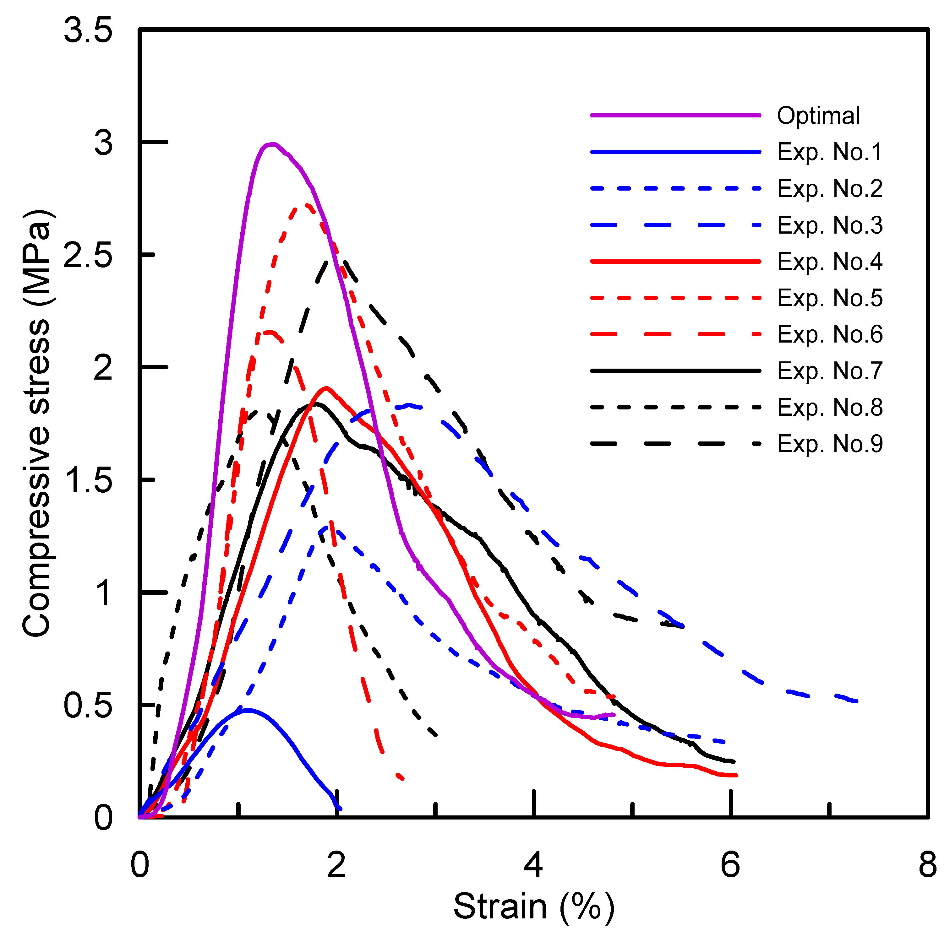
| Exp. No. | Setting Parameters | Compressive Strength | |
|---|---|---|---|
| Exp. Results (Mpa) | S/N (dB) | ||
| 1 | A1B1C1D1 | 0.48 | −8.29 |
| 2 | A1B2C2D2 | 1.29 | 1.29 |
| 3 | A1B3C3D3 | 1.83 | 4.61 |
| 4 | A2B1C2D3 | 1.90 | 5.36 |
| 5 | A2B2C3D1 | 2.73 | 8.37 |
| 6 | A2B3C1D2 | 2.15 | 5.98 |
| 7 | A3B1C3D2 | 1.83 | 4.69 |
| 8 | A3B2C1D3 | 1.81 | 4.64 |
| 9 | A3B3C2D1 | 2.5 | 12.14 |
| Factor | DOF | Average S/N Values | ∆ | SS | MS | F | P (%) | ||
|---|---|---|---|---|---|---|---|---|---|
| Level 1 | Level 2 | Level 3 | |||||||
| A, Binder content | 2 | −0.79 | 6.57 | 7.15 | 7.94 | 494.7 | 247.3 | 1.19 | 36.3 |
| B, Applied pressure | 2 | 0.59 | 4.77 | 7.57 | 6.98 | 364.1 | 182.1 | 0.87 | 26.7 |
| C, Processing time | 2 | 0.78 | 6.26 | 5.89 | 5.48 | 310.9 | 155.4 | 0.75 | 22.8 |
| D, Processing temperature | 2 | 4.07 | 3.99 | 4.87 | 0.88 | 146.3 | 73.2 | 0.35 | 10.7 |
| Error | 18 | − | − | − | − | 417.1 | 23.2 | − | 3.40 |
| Total | 26 | − | − | − | − | 1733 | − | − | 100 |
Publisher’s Note: MDPI stays neutral with regard to jurisdictional claims in published maps and institutional affiliations. |
© 2022 by the authors. Licensee MDPI, Basel, Switzerland. This article is an open access article distributed under the terms and conditions of the Creative Commons Attribution (CC BY) license (https://creativecommons.org/licenses/by/4.0/).
Share and Cite
Lin, C.-C.; Yang, C.-L. A Water-Soluble Core for Manufacturing Hollow Injection-Molded Products. Polymers 2022, 14, 2185. https://doi.org/10.3390/polym14112185
Lin C-C, Yang C-L. A Water-Soluble Core for Manufacturing Hollow Injection-Molded Products. Polymers. 2022; 14(11):2185. https://doi.org/10.3390/polym14112185
Chicago/Turabian StyleLin, Chung-Chih, and Chao-Long Yang. 2022. "A Water-Soluble Core for Manufacturing Hollow Injection-Molded Products" Polymers 14, no. 11: 2185. https://doi.org/10.3390/polym14112185
APA StyleLin, C.-C., & Yang, C.-L. (2022). A Water-Soluble Core for Manufacturing Hollow Injection-Molded Products. Polymers, 14(11), 2185. https://doi.org/10.3390/polym14112185