
Weld Strength of Friction Welding of Dissimilar Polymer Rods Fabricated by Fused Deposition Modeling


Abstract
:
1. Introduction
2. Experimental Details
3. Results and Discussion
4. Conclusions
- The remarkable findings in this study are very practical and provide potential applications in the research and development stage because this technique can be used to fabricate functional components for functional testing in the industry.
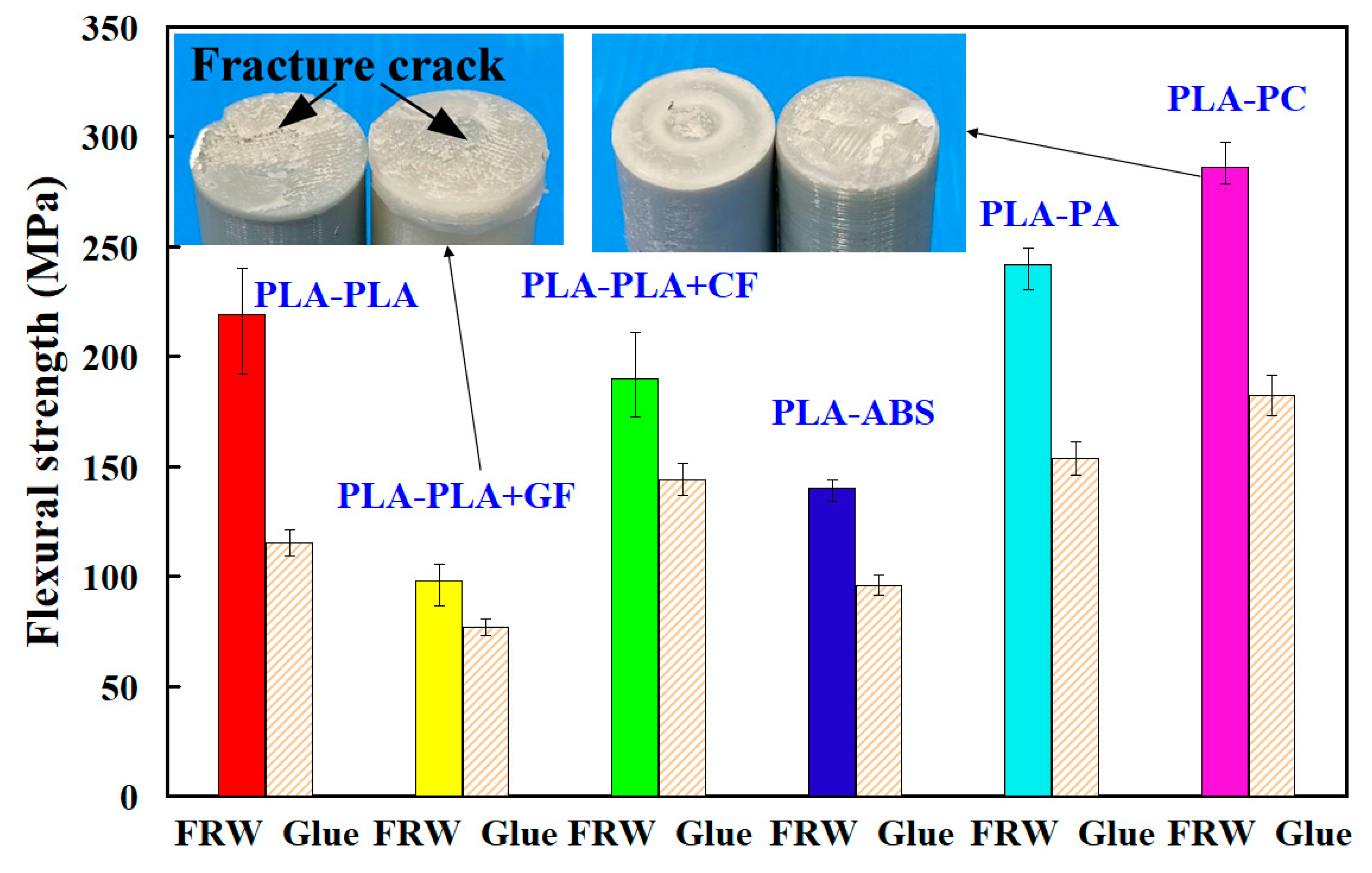
- FRW to weld dissimilar polymer rods has a significantly better bending strength than the use of glue to join dissimilar polymer rods.
- The average flexural strength of dissimilar polymer rods fabricated by FRW is about 1.52 times of that of using glue to join dissimilar polymer rods. The highest flexure strength can be obtained by FRW using PLA to PC rods.
- The average impact strength of dissimilar polymer rods fabricated by FRW is about 1.04 times of that of dissimilar polymer rods jointed by gluing. The highest impact strength can be obtained by FRW using PLA to PLA rods.
Author Contributions
Funding
Institutional Review Board Statement
Informed Consent Statement
Data Availability Statement
Conflicts of Interest
References
- Li, B.; Liu, Q.; Jia, S.; Ren, Y.; Yang, P. Effect of V Content and Heat Input on HAZ Softening of Deep-Sea Pipeline Steel. Materials 2022, 15, 794. [Google Scholar] [CrossRef]
- Yin, P.; Xu, C.; Pan, Q.; Zhang, W.; Jiang, X. Effect of Different Ultrasonic Power on the Properties of RHA Steel Welded Joints. Materials 2022, 15, 768. [Google Scholar] [CrossRef]
- Hassan, A.J.; Boukharouba, T.; Miroud, D. Concept of forge application under effect of friction time for AISI 316 using friction welding process. Int. J. Adv. Manuf. Technol. 2021, 112, 2223–2231. [Google Scholar] [CrossRef]
- Delijaicov, S.; Rodrigues, M.; Farias, A.; Neves, M.; Bortolussi, R.; Miyazaki, M.; Brandão, F. Microhardness and residual stress of dissimilar and thick aluminum plates AA7181-T7651 and AA7475-T7351 using bobbin, top, bottom, and double-sided FSW methods. Int. J. Adv. Manuf. Technol. 2020, 108, 277–287. [Google Scholar] [CrossRef]
- Lambiase, F.; Grossi, V.; Paoletti, A. Effect of tilt angle in FSW of polycarbonate sheets in butt configuration. Int. J. Adv. Manuf. Technol. 2020, 107, 489–501. [Google Scholar] [CrossRef]
- Kumaran, S.S.; Muthukumaran, S. Effect of projection on joint properties of friction welding of tube-to-tube plate using an external tool. Int. J. Adv. Manuf. Technol. 2014, 75, 1723–1733. [Google Scholar] [CrossRef]
- Hynes, N.R.J.; Velu, P.S. Simulation of friction welding of alumina and steel with aluminum interlayer. Int. J. Adv. Manuf. Technol. 2017, 93, 121–127. [Google Scholar] [CrossRef]
- Azizieh, M.; Khamisi, M.; Lee, D.J.; Yoon, E.Y.; Kim, H.S. Characterizations of dissimilar friction welding of ST37 and CK60 steels. Int. J. Adv. Manuf. Technol. 2016, 85, 2773–2781. [Google Scholar] [CrossRef]
- Winiczenko, R. Effect of friction welding parameters on the tensile strength and microstructural properties of dissimilar AISI 1020-ASTM A536 joints. Int. J. Adv. Manuf. Technol. 2016, 84, 941–955. [Google Scholar] [CrossRef] [Green Version]
- Wang, G.L.; Li, J.L.; Wang, W.L.; Xiong, J.T.; Zhang, F.S. Rotary friction welding on dissimilar metals of aluminum and brass by using pre-heating method. Int. J. Adv. Manuf. Technol. 2018, 99, 1293–1300. [Google Scholar] [CrossRef]
- Rehmani, M.A.A.; Jaywant, S.A.; Arif, K.M. Study of Microchannels Fabricated Using Desktop Fused Deposition Modeling Systems. Micromachines 2021, 12, 14. [Google Scholar] [CrossRef] [PubMed]
- Pitaru, A.A.; Lacombe, J.-G.; Cooke, M.E.; Beckman, L.; Steffen, T.; Weber, M.H.; Martineau, P.A.; Rosenzweig, D.H. Investigating Commercial Filaments for 3D Printing of Stiff and Elastic Constructs with Ligament-Like Mechanics. Micromachines 2020, 11, 846. [Google Scholar] [CrossRef] [PubMed]
- Khorasani, M.; Ghasemi, A.; Rolfe, B.; Gibson, I. Additive manufacturing a powerful tool for the aerospace industry. Rapid Prototyp. J. 2021, 28, 87–100. [Google Scholar] [CrossRef]
- Xu, J.; Liu, K.; Liu, Z.; Zhang, F.; Zhang, S.; Tan, J. Electrothermal response optimization of nozzle structure for multi-material rapid prototyping based on fuzzy adaptive control. Rapid Prototyp. J. 2022, 28, 1168–1181. [Google Scholar] [CrossRef]
- Dave, H.K.; Karumuri, R.T.; Prajapati, A.R.; Rajpurohit, S.R. Specific energy absorption during compression testing of ABS and FPU parts fabricated using LCD-SLA based 3D printer. Rapid Prototyp. J. 2022. [Google Scholar] [CrossRef]
- Herzog, T.; Schnell, G.; Tille, C.; Seitz, H. Investigation of suitable material and adhesion promoter combinations for fused filament fabrication on flexible silicone build plates. Rapid Prototyp. J. 2022. [Google Scholar] [CrossRef]
- Kotz, F.; Mader, M.; Dellen, N.; Risch, P.; Kick, A.; Helmer, D.; Rapp, B.E. Fused Deposition Modeling of Microfluidic Chips in Polymethylmethacrylate. Micromachines 2020, 11, 873. [Google Scholar] [CrossRef] [PubMed]
- Xu, S.; Huang, J.; Liu, J.; Ma, Y. Topology Optimization for FDM Parts Considering the Hybrid Deposition Path Pattern. Micromachines 2020, 11, 709. [Google Scholar] [CrossRef] [PubMed]
- Monkova, K.; Vasina, M.; Monka, P.P.; Vanca, J.; Kozak, D. Effect of 3D-Printed PLA Structure on Sound Reflection Properties. Polymers 2022, 14, 413. [Google Scholar] [CrossRef]
- Vidakis, N.; Petousis, M.; Velidakis, E.; Korlos, A.; Kechagias, J.D.; Tsikritzis, D.; Mountakis, N. Medical-Grade Polyamide 12 Nanocomposite Materials for Enhanced Mechanical and Antibacterial Performance in 3D Printing Applications. Polymers 2022, 14, 440. [Google Scholar] [CrossRef]
- Bubmann, T.; Seidel, A.; Ruckdäschel, H.; Altstädt, V. Transparent PC/PMMA Blends with Enhanced Mechanical Properties via Reactive Compounding of Functionalized Polymers. Polymers 2022, 14, 73. [Google Scholar] [CrossRef] [PubMed]
- Nassar, A.; Younis, M.; Elzareef, M.; Nassar, E. Effects of Heat-Treatment on Tensile Behavior and Dimension Stability of 3D Printed Carbon Fiber Reinforced Composites. Polymers 2021, 13, 4305. [Google Scholar] [CrossRef]
- Popescu, D.; Baciu, F.; Amza, C.G.; Cotrut, C.M.; Marinescu, R. The Effect of Disinfectants Absorption and Medical Decontamination on the Mechanical Performance of 3D-Printed ABS Parts. Polymers 2021, 13, 4249. [Google Scholar] [CrossRef] [PubMed]
- Alshammari, Y.L.A.; He, F.; Khan, M.A. Modelling and Investigation of Crack Growth for 3D-Printed Acrylonitrile Butadiene Styrene (ABS) with Various Printing Parameters and Ambient Temperatures. Polymers 2021, 13, 3737. [Google Scholar] [CrossRef]
- Bernal, J.D.B.; Silva, E.C.N.; Rubio, W.M. Characterization of effective Young’s modulus for Fused Deposition Modeling manufactured topology optimization designs. Int. J. Adv. Manuf. Technol. 2019, 103, 2879–2892. [Google Scholar] [CrossRef]
- Lin, S.; Xia, L.; Ma, G.; Zhou, S.; Xie, Y.M. A maze-like path generation scheme for fused deposition modeling. Int. J. Adv. Manuf. Technol. 2019, 104, 1509–1519. [Google Scholar] [CrossRef]
- Paggi, R.A.; Salmoria, G.V.; Ghizoni, G.B.; Back, H.D.M.; Gindri, I.D.M. Structure and mechanical properties of 3D-printed cellulose tablets by fused deposition modeling. Int. J. Adv. Manuf. Technol. 2019, 100, 2767–2774. [Google Scholar] [CrossRef]
- Camposeco-Negrete, C. Optimization of printing parameters in fused deposition modeling for improving part quality and process sustainability. Int. J. Adv. Manuf. Technol. 2020, 108, 2131–2147. [Google Scholar] [CrossRef]
- Liu, W.; Li, Y.; Liu, B.; Wang, G. Development of a novel rectangular–circular grid filling pattern of fused deposition modeling in cellular lattice structures. Int. J. Adv. Manuf. Technol. 2020, 108, 3419–3436. [Google Scholar] [CrossRef]
- Liu, T.; Deng, Z.; Lv, L.; Yi, J.; She, S.; Wan, L. Theoretical and experimental study of temperature field in noncircular high-speed grinding. Int. J. Adv. Manuf. Technol. 2020, 107, 3581–3592. [Google Scholar] [CrossRef]
- Formisano, A.; Durante, M.; Viscusi, A.; Carrino, L. Mechanical behavior and collapse mechanisms of innovative aluminum foam-based sandwich panels under three-point bending. Int. J. Adv. Manuf. Technol. 2021, 112, 1631–1639. [Google Scholar] [CrossRef]
- Mitra, S.; de Castro, A.R.; El Mansori, M. The effect of ageing process on three-point bending strength and permeability of 3D printed sand molds. Int. J. Adv. Manuf. Technol. 2018, 97, 1241–1251. [Google Scholar] [CrossRef] [Green Version]
- Saleh, R.; Barth, M.; Eberhardt, W.; Zimmermann, A. Bending Setups for Reliability Investigation of Flexible Electronics. Micromachines 2021, 12, 78. [Google Scholar] [CrossRef] [PubMed]
- Wu, B.; Meng, W.; Xia, J.; Xiao, P. Influence of Basalt Fibers on the Crack Resistance of Asphalt Mixtures and Mechanism Analysis. Materials 2022, 15, 744. [Google Scholar] [CrossRef]
- Kirmasha, Y.K.; Sharba, M.J.; Leman, Z.; Sultan, M.T.H. Mechanical Performance of Unstitched and Silk Fiber-Stitched Woven Kenaf Fiber-Reinforced Epoxy Composites. Materials 2020, 13, 4801. [Google Scholar] [CrossRef]
- Mazzarisi, M.; Campanelli, S.L.; Angelastro, A.; Palano, F.; Dassisti, M. In situ monitoring of direct laser metal deposition of a nickel-based superalloy using infrared thermography. Int. J. Adv. Manuf. Technol. 2021, 112, 157–173. [Google Scholar] [CrossRef]
- Mazen, A.; McClanahan, B.; Weaver, J.M. Factors affecting ultimate tensile strength and impact toughness of 3D printed parts using fractional factorial design. Int. J. Adv. Manuf. Technol. 2022, 119, 2639–2651. [Google Scholar] [CrossRef]
- Estrada, Q.; Vergara-Vázquez, J.; Szwedowicz, D.; Rodriguez-Mendez, A.; Gómez-Vargas, O.A.; Partida-Ochoa, G.; Ortiz-Domínguez, M. Effect of end-clamping constraints on bending crashworthiness of square profiles. Int. J. Adv. Manuf. Technol. 2021, 116, 3115–3134. [Google Scholar] [CrossRef]
- Benkhelladi, A.; Laouici, H.; Bouchoucha, A. Tensile and flexural properties of polymer composites reinforced by flax, jute and sisal fibres. Int. J. Adv. Manuf. Technol. 2020, 108, 895–916. [Google Scholar] [CrossRef]
- Ercoli, R.; Laskowska, D.; Nguyen, V.V.; Le, V.S.; Louda, P.; Łoś, P.; Ciemnicka, J.; Prałat, K.; Renzulli, A.; Paris, E.; et al. Mechanical and Thermal Properties of Geopolymer Foams (GFs) Doped with By-Products of the Secondary Aluminum Industry. Polymers 2022, 14, 703. [Google Scholar] [CrossRef]
- Venegas, R.; Torres, A.; Rueda, A.M.; Morales, M.A.; Arias, M.J.; Porras, A. Development and Characterization of Plantain (Musa paradisiaca) Flour-Based Biopolymer Films Reinforced with Plantain Fibers. Polymers 2022, 14, 748. [Google Scholar] [CrossRef] [PubMed]
- Rahimi, H.; Masoudi, S.; Tolouei-Rad, M. Experimental investigation of the effect of EDM parameters and dielectric type on the surface integrity and topography. Int. J. Adv. Manuf. Technol. 2022, 118, 1767–1778. [Google Scholar] [CrossRef]
- Attar, A.A.; Nia, A.A.; Mazaheri, Y.; Ghassemali, E. Improving the fracture toughness of multi-layered commercial pure aluminum via warm accumulative roll bonding. Int. J. Adv. Manuf. Technol. 2021, 116, 3603–3617. [Google Scholar] [CrossRef]
- Cai, Z.; Du, X.; Zhu, J.; Wang, K.; Zhao, X.; Liu, J.; Li, J.; Liu, J.; Wang, J.; Wang, H. Research on Underwater Wet Laser Self-Fusion Welding Process and Analysis of Microstructure and Properties of TC4 Titanium Alloy Weld. Materials 2022, 15, 3380. [Google Scholar] [CrossRef] [PubMed]
- Andrearczyk, A.; Konieczny, B.; Sokołowski, J. Additively Manufactured Parts Made of a Polymer Material Used for the Experimental Verification of a Component of a High-Speed Machine with an Optimised Geometry—Preliminary Research. Polymers 2021, 13, 137. [Google Scholar] [CrossRef] [PubMed]
- Urbas, U.; Zorko, D.; Vukašinović, N.; Černe, B. Comprehensive Areal Geometric Quality Characterisation of Injection Moulded Thermoplastic Gears. Polymers 2022, 14, 705. [Google Scholar] [CrossRef]
- Ercetin, A.; Akkoyun, F.; Şimşir, E.; Pimenov, D.Y.; Giasin, K.; Gowdru Chandrashekarappa, M.P.; Lakshmikanthan, A.; Wojciechowski, S. Image Processing of Mg-Al-Sn Alloy Microstructures for Determining Phase Ratios and Grain Size and Correction with Manual Measurement. Materials 2021, 14, 5095. [Google Scholar] [CrossRef]
- Zinchenko, A.; Baiul, K.; Krot, P.; Khudyakov, A.; Vashchenko, S.; Banasiewicz, A.; Wróblewski, A. Materials Selection and Design Options Analysis for a Centrifugal Fan Impeller in a Horizontal Conveyor Dryer. Materials 2021, 14, 6696. [Google Scholar] [CrossRef]
- Camargo, J.C.; Machado, A.R.; Almeida, E.C.; de Almeida, V.H. Mechanical and electrical behavior of ABS polymer reinforced with graphene manufactured by the FDM process. Int. J. Adv. Manuf. Technol. 2022, 119, 1019–1033. [Google Scholar] [CrossRef]
- Loskot, J.; Jezbera, D.; Zmrhalová, Z.O.; Nalezinková, M.; Alferi, D.; Lelkes, K.; Voda, P.; Andrýs, R.; Fučíková, A.M.; Hosszú, T.; et al. A Complex In Vitro Degradation Study on Polydioxanone Biliary Stents during a Clinically Relevant Period with the Focus on Raman Spectroscopy Validation. Polymers 2022, 14, 938. [Google Scholar] [CrossRef]


Publisher’s Note: MDPI stays neutral with regard to jurisdictional claims in published maps and institutional affiliations. |
© 2022 by the authors. Licensee MDPI, Basel, Switzerland. This article is an open access article distributed under the terms and conditions of the Creative Commons Attribution (CC BY) license (https://creativecommons.org/licenses/by/4.0/).
Share and Cite
Kuo, C.-C.; Xu, J.-Y.; Lee, C.-H. Weld Strength of Friction Welding of Dissimilar Polymer Rods Fabricated by Fused Deposition Modeling. Polymers 2022, 14, 2582. https://doi.org/10.3390/polym14132582
Kuo C-C, Xu J-Y, Lee C-H. Weld Strength of Friction Welding of Dissimilar Polymer Rods Fabricated by Fused Deposition Modeling. Polymers. 2022; 14(13):2582. https://doi.org/10.3390/polym14132582
Chicago/Turabian StyleKuo, Chil-Chyuan, Jing-Yan Xu, and Chong-Hao Lee. 2022. "Weld Strength of Friction Welding of Dissimilar Polymer Rods Fabricated by Fused Deposition Modeling" Polymers 14, no. 13: 2582. https://doi.org/10.3390/polym14132582
APA StyleKuo, C.-C., Xu, J.-Y., & Lee, C.-H. (2022). Weld Strength of Friction Welding of Dissimilar Polymer Rods Fabricated by Fused Deposition Modeling. Polymers, 14(13), 2582. https://doi.org/10.3390/polym14132582