
Biocomposites Based on Polyamide 11/Diatoms with Different Sized Frustules


 ,
,  and
and
Abstract
:
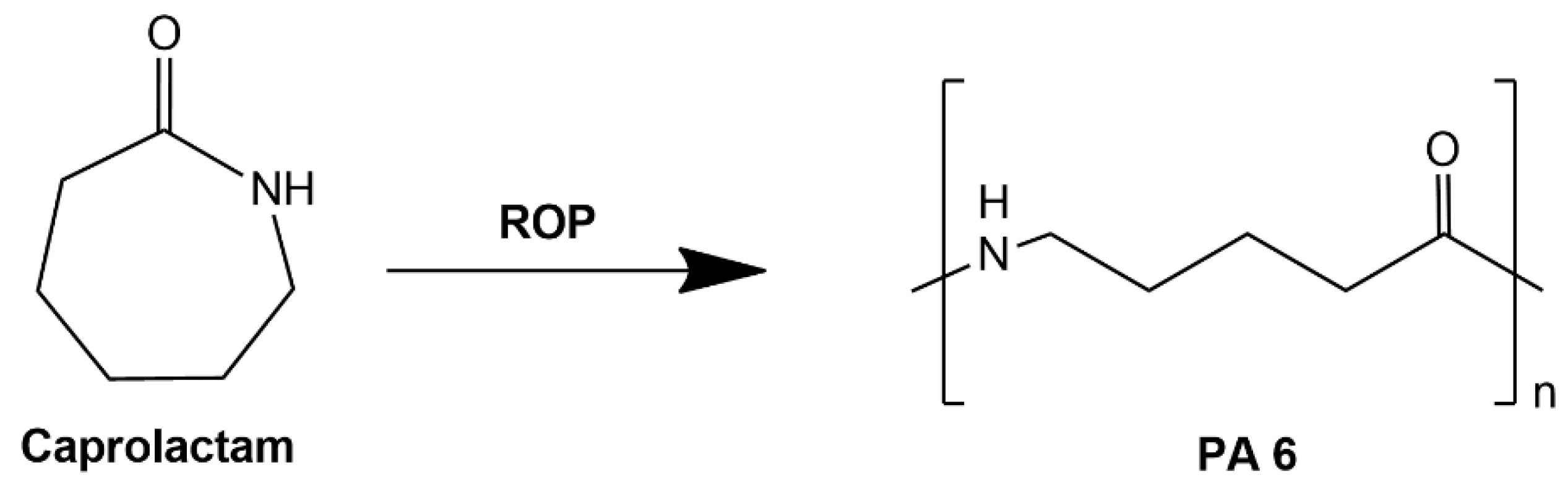
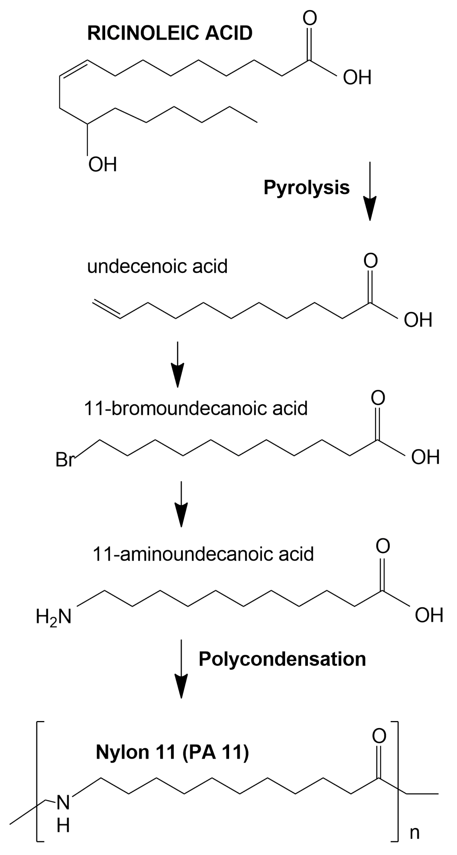
1. Introduction
2. Materials and Methods
2.1. Materials
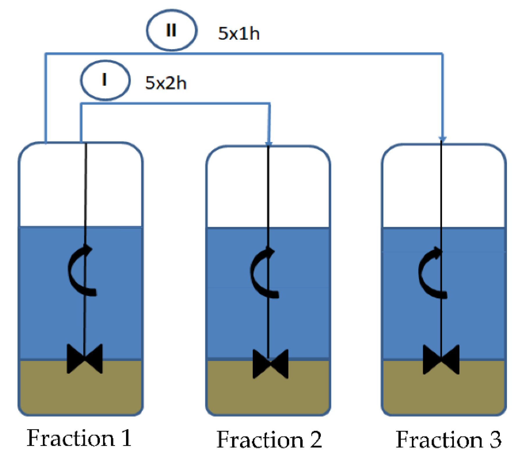
2.2. Preparation of Diatomite
2.3. Extrusion of Biocomposite
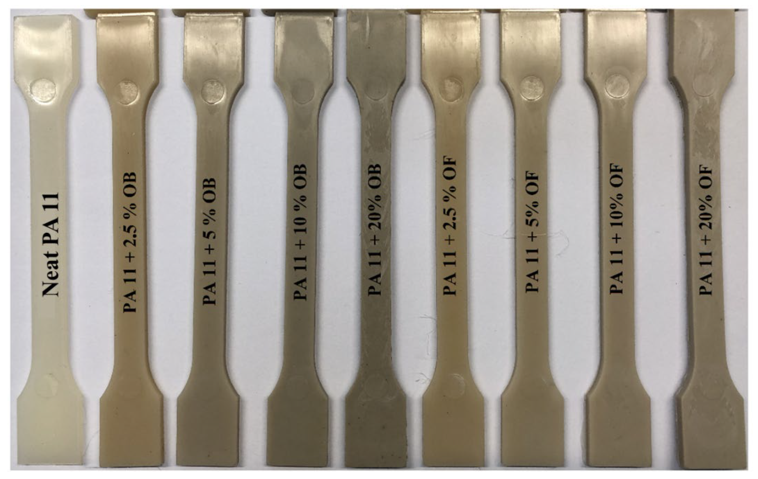
2.4. Injection Molding—To Obtain Standardized Measurement Paddles
2.5. Characterization Methods
3. Results
3.1. Particle Size Distribution of the Modifier (Determined Using DLS)
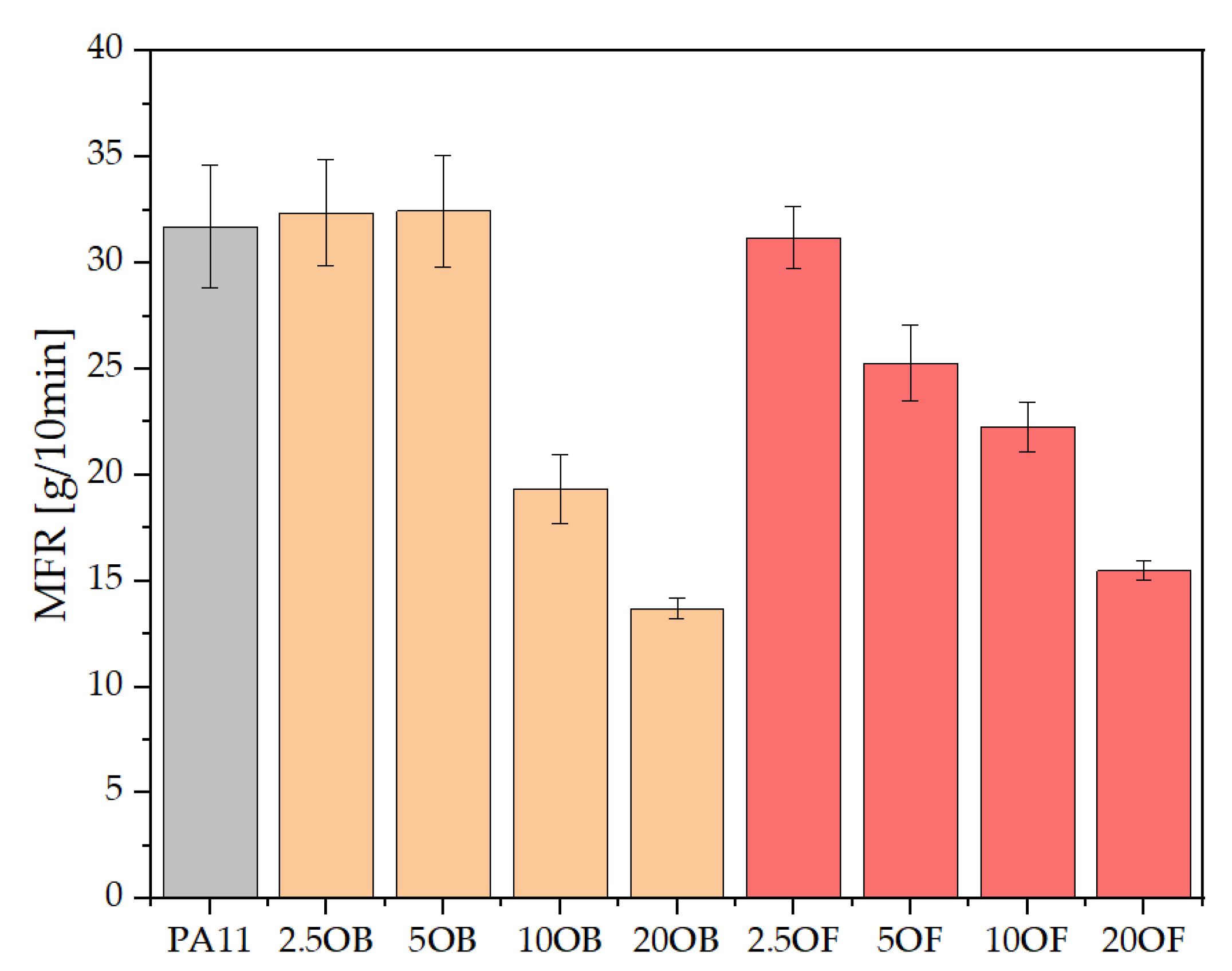
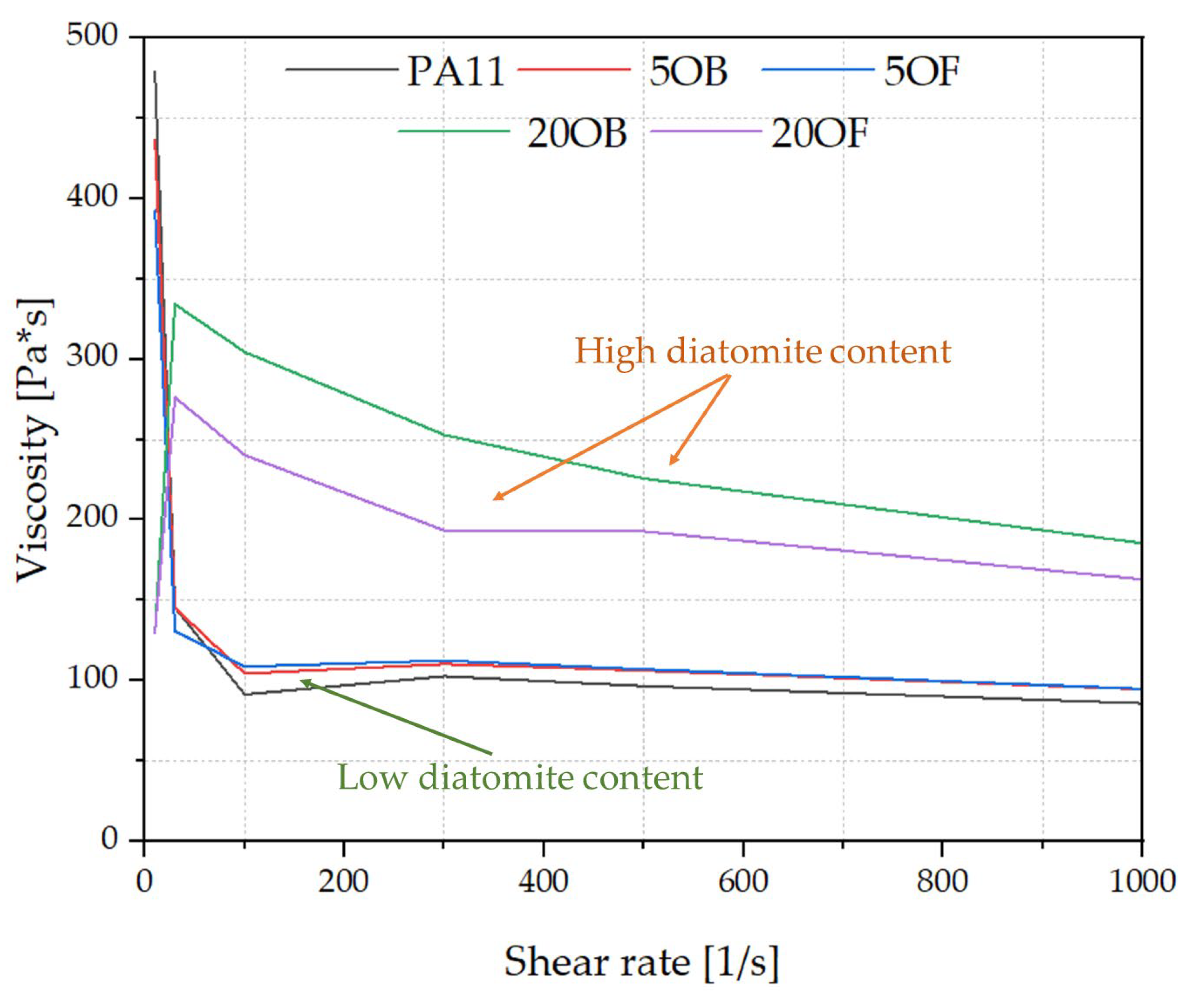
3.2. Rheology—Melt Flow Rate (MFR) and Capillary Rheology
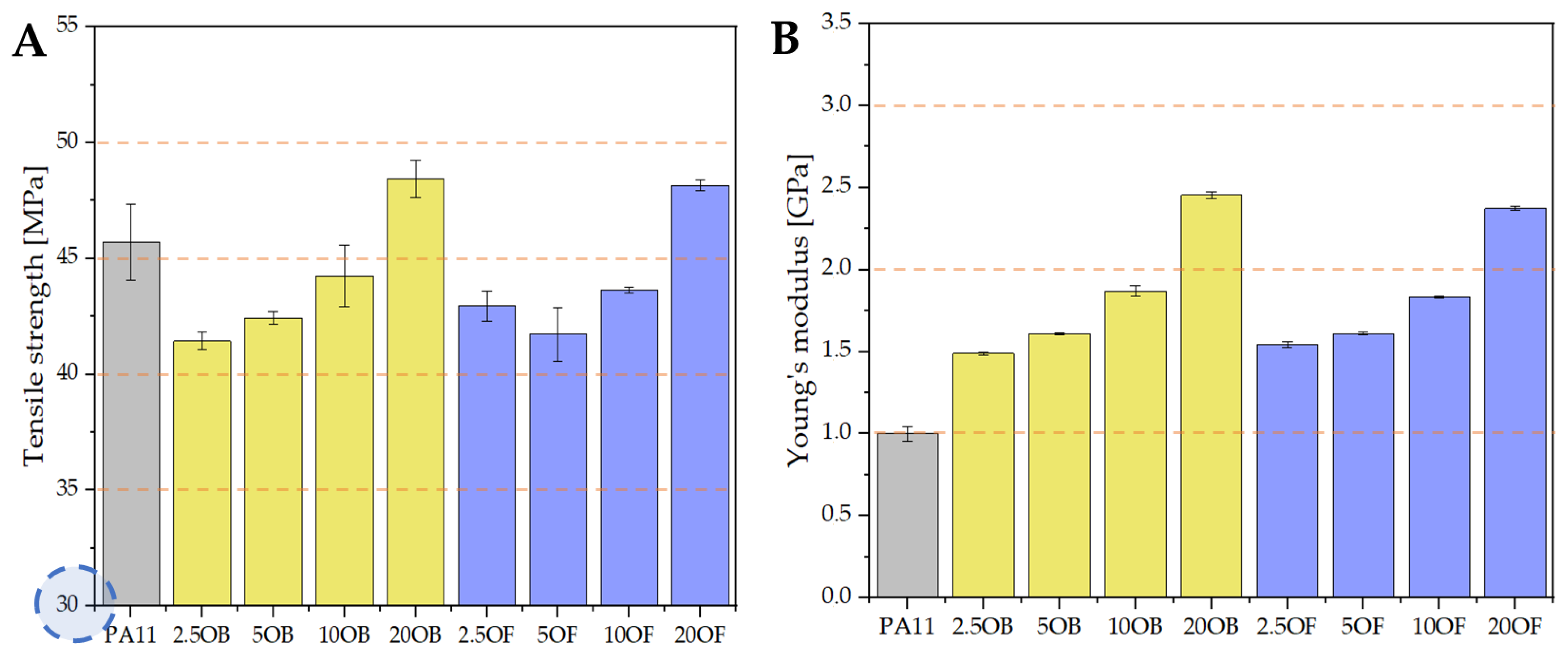
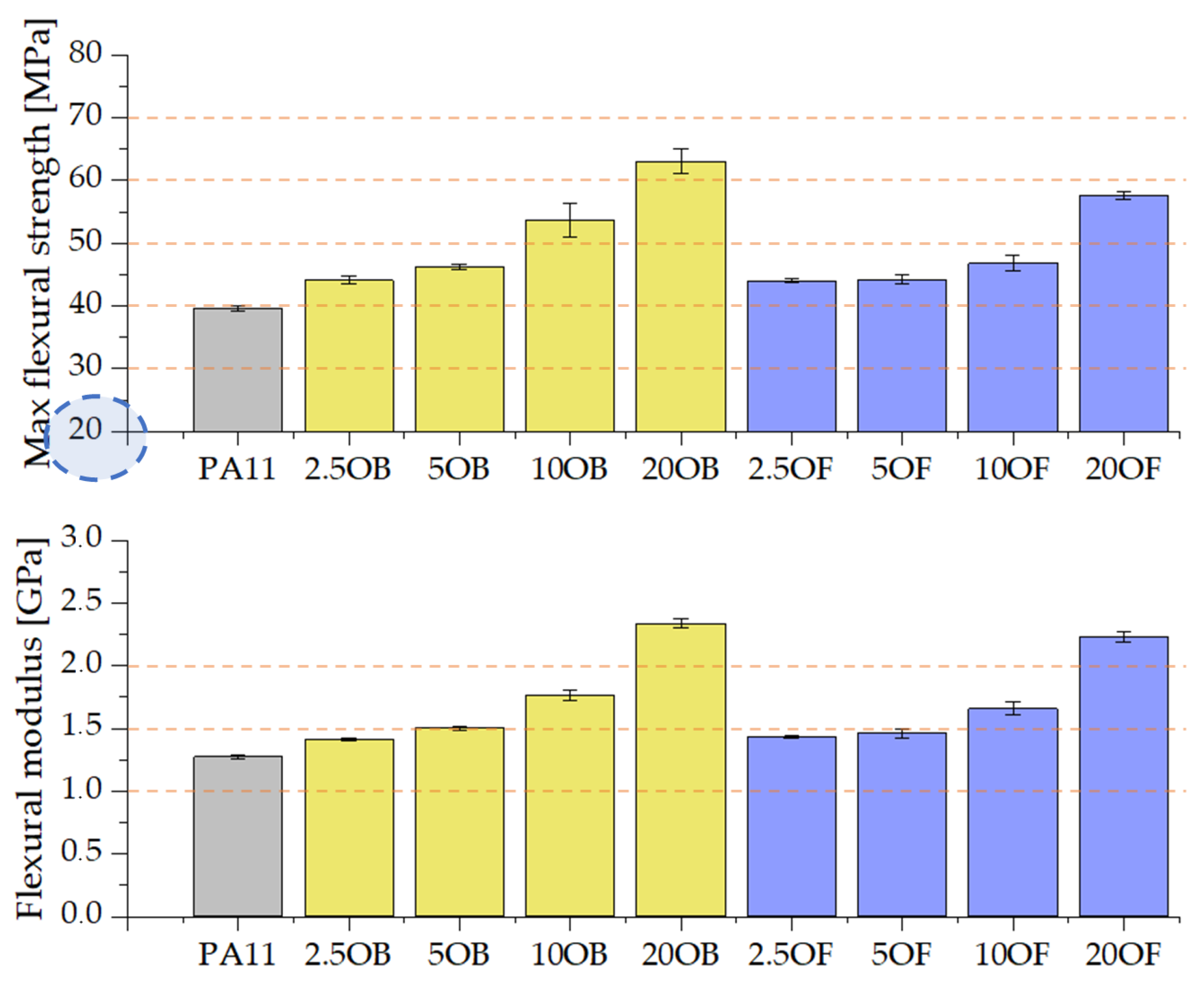
3.3. Mechanical Tests
3.3.1. Tensile Strength
3.3.2. Flexural Strength
3.3.3. The Charpy Impact Test (V-Notch Test)
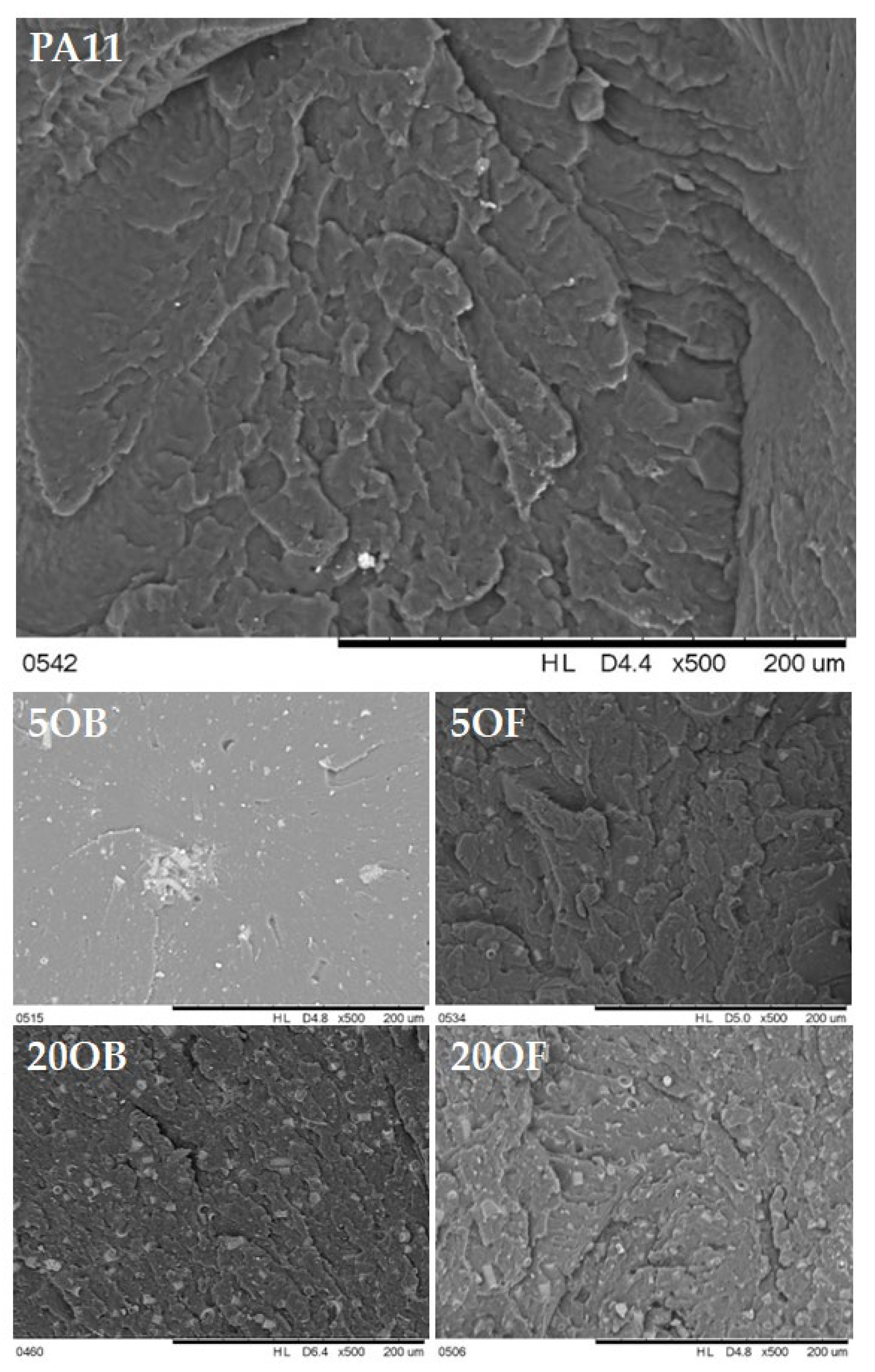
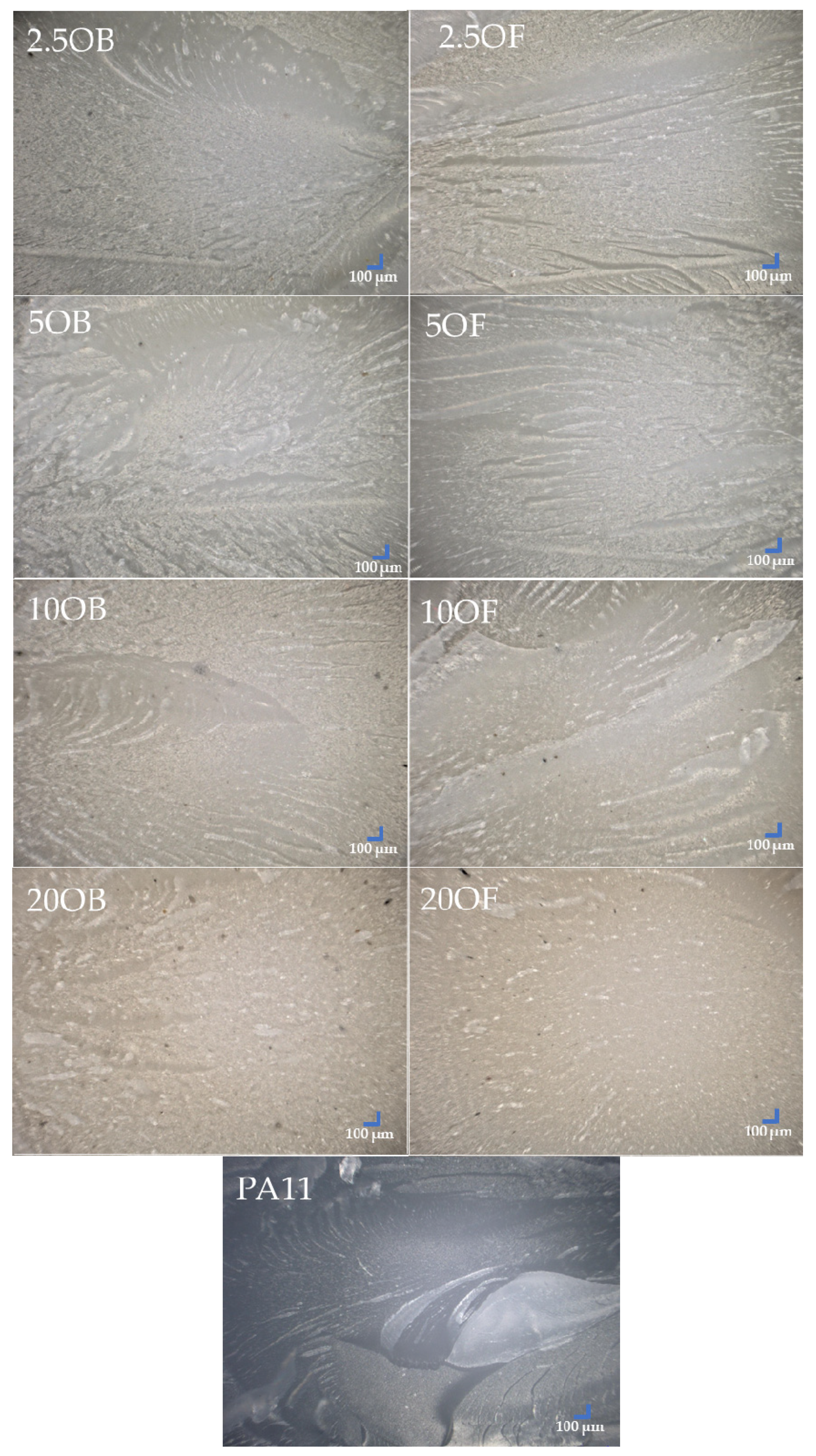
3.4. Morphology of Biocomposite Surfaces
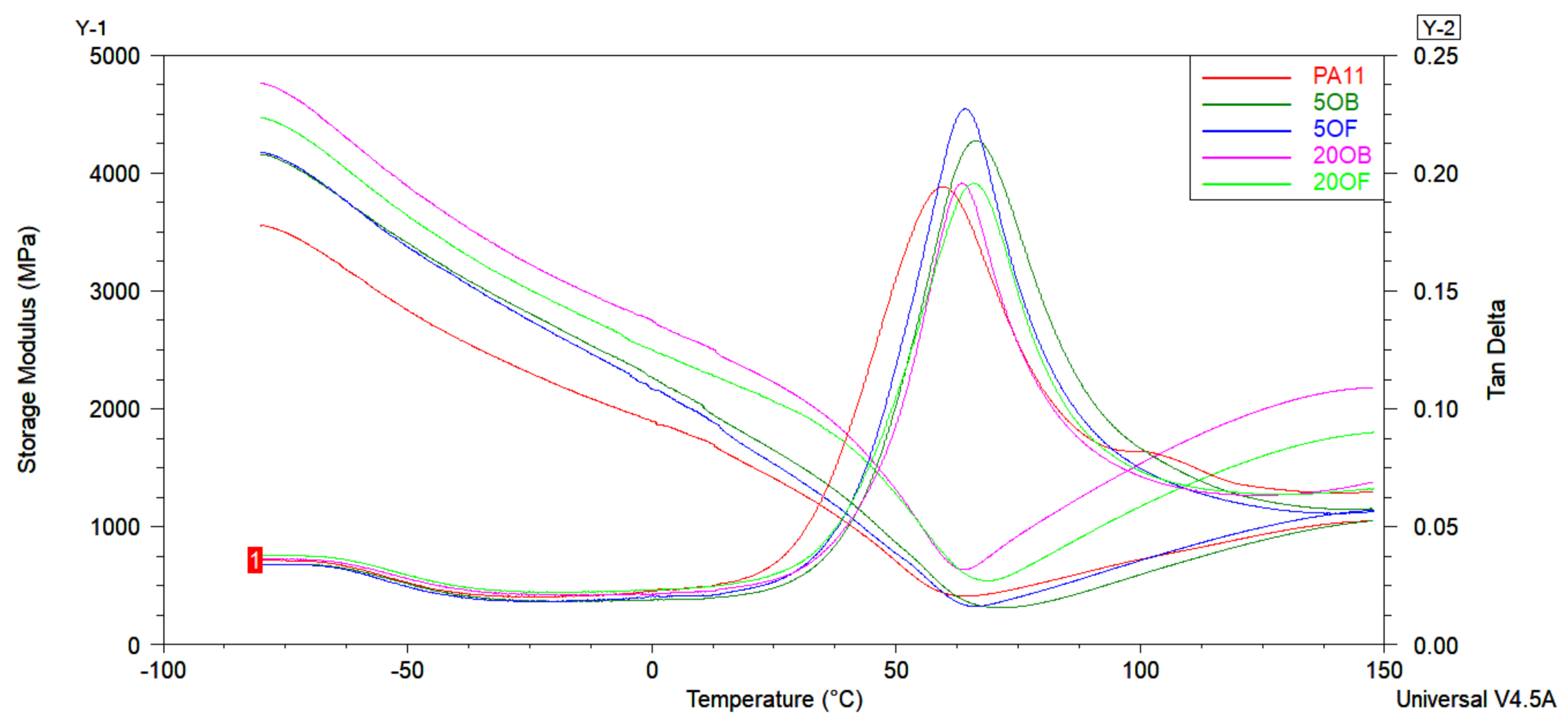
3.5. Thermal Tests
4. Conclusions
Author Contributions
Funding
Institutional Review Board Statement
Informed Consent Statement
Data Availability Statement
Conflicts of Interest
References
- Wypych, G. PA-11 polyamide-11. In Handbook of Polymers; Elsevier: Amsterdam, The Netherlands, 2016; pp. 241–245. [Google Scholar]
- Jariyavidyanont, K.; Mallardo, S.; Cerruti, P.; Di Lorenzo, M.L.; Boldt, R.; Rhoades, A.M.; Androsch, R. Shear-Induced Crystallization of Polyamide 11. Rheol. Acta 2021, 60, 231–240. [Google Scholar] [CrossRef]
- He, D.; Kim, H.C.; De Kleine, R.; Soo, V.K.; Kiziltas, A.; Compston, P.; Doolan, M. Life cycle energy and greenhouse gas emissions implications of polyamide 12 recycling from selective laser sintering for an injection-molded automotive component. J. Ind. Ecol. 2022; early view. [Google Scholar]
- Qian, M.; Xu, X.; Qin, Z.; Yan, S. Silicon carbide whiskers enhance mechanical and anti-wear properties of PA6 towards potential applications in aerospace and automobile fields. Compos. Part B Eng. 2019, 175, 10709. [Google Scholar] [CrossRef]
- Arun, M.; Sathishkumar, N.; Kumar, K.N.; Ajai, S.S.; Aswin, S. Development of patient specific bio-polymer incisor teeth by 3D printing process: A case study. Mater. Today Proc. 2021, 39, 1303–1308. [Google Scholar] [CrossRef]
- Winnacker, M.; Rieger, B. Biobased Polyamides: Recent Advances in Basic and Applied Research. Macromol. Rapid Commun. 2016, 37, 1391–1413. [Google Scholar] [CrossRef] [PubMed]
- Zia, K.; Akram, N.; Tabasum, S.; Noreen, A.; Akbar, M. Processing Technology for Bio-Based Polymers, 1st ed.; Elsevier: Amsterdam, The Netherlands, 2021. [Google Scholar]
- Osváth, Z.; Szőke, A.; Pásztor, S.; Závoczki, L.; Szarka, G.; Iván, B. Recent Advances in the Synthesis and Analysis of Polyamide 6 and Products therefrom: From Polymerization Chemistry of ε-caprolactam to Thermoplastic Resin Transfer Moulding (t-rtm). Acad. J. Polym. Sci. 2020, 4, 555629. [Google Scholar]
- Duddleston, L. Polyamide (Nylon) 12 Degradation during the Selective Laser Sintering (SLS) Process: A Quantification for Recycling Optimization. Master’s Thesis, Mechanical Engineering, University of Wisconsin, Madison, WI, USA, 2015. [Google Scholar]
- Oelmann, S.; Meier, M.A.R. Synthesis of Modified Polycaprolactams Obtained from Renewable Resources. Macromol. Chem. Phys. 2015, 216, 1972–1981. [Google Scholar] [CrossRef]
- Meier, M.A.R. Plant-Oil-Based Polyamides and Polyurethanes: Toward Sustainable Nitrogen-Containing Thermoplastic Materials. Macromol. Rapid Commun. 2019, 40, 1800524. [Google Scholar] [CrossRef]
- Hao, A.; Wong, I.; Wu, H.; Lisco, B.; Ong, B.; Sallean, A.; Butler, S.; Londa, M.; Koo, J. Mechanical, thermal, and flame-retardant performance of polyamide 11–halloysite nanotube nanocomposites. J. Mater. Sci. 2015, 50, 157–167. [Google Scholar] [CrossRef]
- Magniez, K.; Iftikhar, R.; Fox, B.L. Properties of bio-based polymer nylon 11 reinforced with short carbon fiber composites. Polym. Compos. 2015, 36, 668–674. [Google Scholar] [CrossRef]
- Wypych, G. Handbook of Polymers; Elsevier: Amsterdam, The Netherlands, 2022; Volume 230–236, pp. 256–267. [Google Scholar]
- Dong-Hun, L.; Chang, Y.W.; Jang, K.S. Morphology, mechanical properties and shape memory effects of polyamide12/polyolefin elastomer blends compatibilized by glycidylisobutyl POSS. Materials 2020, 14, 27. [Google Scholar]
- Stojšić, J.; Raos, P.; Milinović, A.; Damjanović, D. A Study of the Flexural Properties of PA12/Clay Nanocomposites. Polymers 2022, 14, 434. [Google Scholar] [CrossRef]
- Sathees Kumar, S.; Kanagaraj, G. Investigation on mechanical and tribological behaviors of PA6 and graphite-reinforced PA6 polymer composites. Arab. J. Sci. Eng. 2016, 41, 4347–4357. [Google Scholar] [CrossRef]
- Oliveira, M.J.; Botelho, G. Degradation of polyamide 11 in rotational moulding. Polym. Degrad. Stab. 2008, 93, 139–146. [Google Scholar] [CrossRef]
- Sherman, L.M. Additive manufacturing: Materials for ‘real-world’ parts. Plast. Technol. 2014, 60, 42–47. [Google Scholar]
- Bai, J.; Yuan, S.; Shen, F.; Zhang, B.; Chua, C.K.; Zhou, K.; Wei, J. Toughening of polyamide 11 with carbon nanotubes for additive manufacturing. Virtual Phys. Prototyp. 2017, 12, 235–240. [Google Scholar] [CrossRef]
- Kohan, M.I. (Ed.) Chapter 13 Commercial nylon plastics and their applications. In Nylon Plastics Handbook; Hanser Publishers: Munich, Germany, 1995; pp. 487–599. [Google Scholar]
- Bello, J.O.; Wood, R.J.K. Micro-abrasion of filled and unfilled poly-amide 11 coatings. Wear 2005, 258, 294–302. [Google Scholar] [CrossRef]
- Kausar, A. Advances in Carbon Fiber Reinforced Polyamide-Based Composite Materials. Adv. Mater. Sci. 2009, 19, 67–82. [Google Scholar] [CrossRef] [Green Version]
- Libera, V.; Papa, I.; Lopresto, V.; Mocerino, D.; Filippone, G.; Russo, R. Manufacturing of Bio-Polyamide 11/Basalt Thermoplastic Laminates by Hot Compaction: The Key-Role of Matrix Rheology. J. Thermoplast. Compos. Mater. 2022. [Google Scholar] [CrossRef]
- Pan, B.; Xu, G.; Zhang, B.; Ma, X.; Li, H.; Zhang, Y. Preparation and Tribological Properties of Polyamide 11/Graphene Coatings. Polym.-Plast. Technol. Eng. 2012, 51, 1163–1166. [Google Scholar] [CrossRef]
- Haddou, G.; Dandurand, J.; Dantras, E.; Maiduc, H.; Thai, H.; Vu Giang, N.; Trung, T.H.; Ponteins, P.; Lacabanne, C. Mechanical properties of continuous bamboo fiber-reinforced biobased polyamide 11 composites. Inc. J. Appl. Polym. Sci. 2019, 136, 47623. [Google Scholar] [CrossRef]
- Russo, P.; Simeoli, G.; Vitiello, L.; Filippone, G. Bio-Polyamide 11 Hybrid Composites Reinforced with Basalt/Flax Interwoven Fibers: A Tough Green Composite for Semi-Structural Applications. Fibers 2019, 7, 41. [Google Scholar] [CrossRef] [Green Version]
- Venkatraman, P.; Gohn, A.M.; Rhoades, A.M.; Foster, E.J. Developing high performance PA 11/cellulose nanocomposites for industrial-scale melt processing. Compos. Part B Eng. 2019, 174, 106988. [Google Scholar] [CrossRef]
- Oliver-Ortega, H.; Méndez, J.; Espinach, F.; Tarrés, Q.; Ardanuy, M.; Mutjé, P. Impact Strength and Water Uptake Behaviors of Fully Bio-Based PA11-SGW Composites. Polymers 2018, 10, 717. [Google Scholar] [CrossRef] [PubMed] [Green Version]
- Zierdt, P.; Theumer, T.; Kulkarni, G.; Däumlich, V.; Klehm, J.; Hirsch, U.; Weber, A. Sustainable wood-plastic composites from bio-based polyamide 11 and chemically modified beech fibers. Sustain. Mater. Technol. 2015, 6, 6–14. [Google Scholar] [CrossRef]
- Chang, B.P.; Gupta, A.; Muthuraj, R.; Mekonnen, T.H. Bioresourced fillers for rubber composite sustainability: Current development and future opportunities. Green Chem. 2021, 23, 5337–5378. [Google Scholar] [CrossRef]
- Rosenboom, J.G.; Langer, R.; Traverso, G. Bioplastics for a circular economy. Nat. Rev. Mater. 2022, 7, 117–137. [Google Scholar] [CrossRef] [PubMed]
- Zheng, J.; Suh, S. Strategies to reduce the global carbon footprint of plastics. Nat. Clim. Change 2019, 9, 374–378. [Google Scholar] [CrossRef]
- Danil de Namor, A.F.; El Gamouz, A.; Frangie, S.; Martinez, V.; Valiente, L.; Webb, O.A. Turning the volume down on heavy metals using tuned diatomite. A review of diatomite and modified diatomite for the extraction of heavy metals from water. J. Hazard. Mater. 2012, 241–242, 14–31. [Google Scholar] [CrossRef]
- Sedai, B.R.; Khatiwada, B.K.; Mortazavian, H.; Blum, F.D. Development of superhydrophobicity in fluorosilane-treated diatomaceous earth polymer coatings. Appl. Surf. Sci. 2016, 386, 178–186. [Google Scholar] [CrossRef]
- Dobrosielska, M.; Dobrucka, R.; Gloc, M.; Brząkalski, D.; Szymański, M.; Kurzydłowski, K.J.; Przekop, R.E. A New Method of Diatomaceous Earth Fractionation—A Bio-Raw Material Source for Epoxy-Based Composites. Materials 2021, 14, 1663. [Google Scholar] [CrossRef]
- Dobrosielska, M.; Dobrucka, R.; Brząkalski, D.; Gloc, M.; Rębiś, J.; Głowacka, J.; Kurzydłowski, K.J.; Przekop, R.E. Przekop, Methodological Aspects of Obtaining and Characterizing Composites Based on Biogenic Diatomaceous Silica and Epoxy Resins. Materials 2021, 14, 4607. [Google Scholar] [CrossRef] [PubMed]
- Dobrosielska, M.; Dobrucka, R.; Brząkalski, D.; Frydrych, M.; Kozera, P.; Wieczorek, M.; Jałbrzykowski, M.; Kurzydłowski, K.J.; Przekop, R.E. Influence of Diatomaceous Earth Particle Size on Mechanical Properties of PLA/Diatomaceous Earth Composites. Materials 2022, 15, 3607. [Google Scholar] [CrossRef] [PubMed]
- Dobrosielska, M.; Przekop, R.E.; Sztorch, B.; Brząkalski, D.; Zgłobicka, I.; Łępicka, M.; Dobosz, R.; Kurzydłowski, K.J. Biogenic Composite Filaments Based on Polylactide and Diatomaceous Earth for 3D Printing. Materials 2020, 13, 4632. [Google Scholar] [CrossRef]
- Zhu, F.; Yu, B.; Su, J.; Han, J. Study on PLA/PA11 bio-based toughening melt-blown nonwovens. AUTEX Res. J. 2020, 20, 24–31. [Google Scholar] [CrossRef] [Green Version]
- Gug, J.; Sobkowicz, M.J. Effect of Catalyst on Compatibilization of Poly(lactic acid)/Polyamide Blends. In Proceedings of the Annual Technical Conference—ANTEC, Orlando, FL, USA, 23–25 March 2015. [Google Scholar]
- Ortega, H.O.; Méndez, J.A.; Mutjé, P.; Tarrés, Q.; Espinach, F.X.; Mònica Ardanuy, M. Evaluation of Thermal and Thermomechanical Behaviour of Bio-Based Polyamide 11 Based Composites Reinforced with Lignocellulosic Fibres. Polymers 2017, 9, 522. [Google Scholar] [CrossRef] [Green Version]
- Stoclet, G.; Sclavons, M.; Devaux, J. Relations between structure and property of polyamide 11 nanocomposites based on raw clays elaborated by water-assisted extrusion. J. Appl. Polym. Sci. 2013, 127, 4809–4824. [Google Scholar] [CrossRef]
- Castagnet, S.; Thilly, L. High-pressure dependence of structural evolution in polyamide 11 during annealing. J. Polym. Sci. Part B Polym. Phys. 2009, 47, 2015–2025. [Google Scholar] [CrossRef]
- Mancic, L.; Osman, R.F.M.; Costa, A.M.L.M.; d’Almeida, J.R.M.; Marinkovic, B.A.; Rizzo, F.C. Thermal and mechanical properties of polyamide 11 based composites reinforced with surface modified titanate nanotubes. Mater. Des. 2015, 83, 459–467. [Google Scholar] [CrossRef]
- Feng, N.; Wang, X.; Wu, D. Surface modification of recycled carbon fiber and its reinforcement effect on nylon 6 composites: Mechanical properties, morphology and crystallization behaviors. Curr. Appl. Phys. 2013, 13, 2038–2050. [Google Scholar] [CrossRef]


| PA 11 | PA 12 | PA 6 | |
|---|---|---|---|
| Tc (°C) | 142–158.8 | 147–148 | 191.8–193.2 |
| Tm (°C) | 176–198 | 174–185 | 220–260 |
| Tg (°C) | 35–46 | 55 | 50–75 |
| Polydispersity Mm/Mn | 1.72–2.50 | 1.54–3.5 | 1.7–2.4 |
| Crystallinity (%) | 16.8–36 | 30–52 | 24.4–50 |
| Tensile strength (MPa) | 40.53–42 | 50–70 | 74–106 |
| Tensile modulus (MPa) | 1288.83–1300 | 1.400–1.600 | 780–3.000 |
| Izod impact strength (kJ/m2) | 13.49 | 30 | 17 |
| Charpy impact strength (kJ/m2) | 5–15 | 6–25 | 3.5–82 |
| Flexural strength (MPa) | ~45 | 60.7 | 100 |
| Flexural modulus (MPa) | 290–1060 | 360–1260 | 2.600 |
| Shore D hardness | 64–75 | 61–79 | 78.5–82 |
| Weight of Sediment (kg) | Percentage (%) | Times Washed | |
|---|---|---|---|
| Fraction 1 | 1.785 | 11.90 | 10 |
| Fraction 2 | 10.561 | 70.40 | 5 |
| Fraction 3 | 0.952 | 6.35 | 5 |
| Total | 13.298 | 88.65 | - |
| Temperature at heating zones (°C) | Nozzle | TS6 | TS5 | TS4 | TS3 | TS2 | TS1 |
| 235 | 250 | 250 | 255 | 255 | 250 | 250 | |
| Torque, M (Nm) | Nozzle pressure, P50 (bar) | Revolutions per minute, N (1/min) | |||||
| 20–78 | 0.6 | 14 | |||||
| Temperature (°C) | Nozzle | Zone 1 | Zone 2 | Zone 3 | Traverse |
| 215 | 220 | 215 | 210 | 40 | |
| Mold closing force (kN) | Clamping time (s) | Cooling down time (s) | Screw diameter (mm) | ||
| 800 | 4 | 30 | 25 | ||
| Biocomposite Type | Filler Concentration | Abbreviation |
|---|---|---|
| PA11 + original diatoms | 2.5% | 2.5OB |
| 5% | 5OB | |
| 10% | 10OB | |
| 20% | 20OB | |
| PA11 + fractionated diatoms | 2.5% | 2.5OF |
| 5% | 5OF | |
| 10% | 10OF | |
| 20% | 20OF | |
| PA11 | - | PA11 |
| Gloss 60° (GU) | SD (GU) | Gloss 60° (GU) | SD (GU) | ||
|---|---|---|---|---|---|
| 2.5OB | 24.53 | 0.50 | 2.5OF | 23.00 | 0.08 |
| 5OB | 21.90 | 0.54 | 5OF | 35.70 | 1.13 |
| 10OB | 17.50 | 2.12 | 10OF | 26.10 | 0.75 |
| 20OB | 15.07 | 0.74 | 20OF | 16.57 | 0.12 |
| PA11 | 31.50 | 1.93 | |||
| Sample | Tg (◦C) |
|---|---|
| PA11 | 50.0 |
| 5OB | 55.8 |
| 5OF | 55.7 |
| 20OB | 52.7 |
| 20OF | 53.9 |
| 1st Heating | Cooling | 2nd Heating | |||||||
|---|---|---|---|---|---|---|---|---|---|
| Sample | Tg (°C) | Tm (°C) | ΔHm (J/g) | Tc (°C) | ΔHc (J/g) | Tm1 (°C) | Tm2 (°C) | ΔHm (J/g) | Xc (%) |
| PA11 | 48.7 | 190.0 | 56.9 | 163.9 | 53.2 | 181.4 | 189.0 | 51.6 | 25.0 |
| 5OB | 46.8 | 189.5 | 44.6 | 167.6 | 50.4 | 182.6 | 189.0 | 45.0 | 22.9 |
| 5OF | 44.0 | 189.5 | 48.7 | 167.1 | 49.11 | 182.8 | 188.6 | 50.3 | 25.7 |
| 200B | 44.6 | 187.6 | 36.4 | 167.8 | 50.7 | - | 186.6 | 44.1 | 26.7 |
| 20OF | 46.6 | 188.7 | 39.2 | 169.7 | 51.5 | - | 188.4 | 44.7 | 27.1 |
Publisher’s Note: MDPI stays neutral with regard to jurisdictional claims in published maps and institutional affiliations. |
© 2022 by the authors. Licensee MDPI, Basel, Switzerland. This article is an open access article distributed under the terms and conditions of the Creative Commons Attribution (CC BY) license (https://creativecommons.org/licenses/by/4.0/).
Share and Cite
Dobrosielska, M.; Dobrucka, R.; Kozera, P.; Kozera, R.; Kołodziejczak, M.; Gabriel, E.; Głowacka, J.; Jałbrzykowski, M.; Kurzydłowski, K.J.; Przekop, R.E. Biocomposites Based on Polyamide 11/Diatoms with Different Sized Frustules. Polymers 2022, 14, 3153. https://doi.org/10.3390/polym14153153
Dobrosielska M, Dobrucka R, Kozera P, Kozera R, Kołodziejczak M, Gabriel E, Głowacka J, Jałbrzykowski M, Kurzydłowski KJ, Przekop RE. Biocomposites Based on Polyamide 11/Diatoms with Different Sized Frustules. Polymers. 2022; 14(15):3153. https://doi.org/10.3390/polym14153153
Chicago/Turabian StyleDobrosielska, Marta, Renata Dobrucka, Paulina Kozera, Rafał Kozera, Marta Kołodziejczak, Ewa Gabriel, Julia Głowacka, Marek Jałbrzykowski, Krzysztof J. Kurzydłowski, and Robert E. Przekop. 2022. "Biocomposites Based on Polyamide 11/Diatoms with Different Sized Frustules" Polymers 14, no. 15: 3153. https://doi.org/10.3390/polym14153153
APA StyleDobrosielska, M., Dobrucka, R., Kozera, P., Kozera, R., Kołodziejczak, M., Gabriel, E., Głowacka, J., Jałbrzykowski, M., Kurzydłowski, K. J., & Przekop, R. E. (2022). Biocomposites Based on Polyamide 11/Diatoms with Different Sized Frustules. Polymers, 14(15), 3153. https://doi.org/10.3390/polym14153153