Abstract
Organic–inorganic nanocomposite fibers can avoid the agglomeration of single nanoparticles and reduce the cost (nanoparticles assembled on the surface of nanofibers), but also can produce new chemical, electrical, optical, and other properties, with a composite synergistic effect. Aromatic polyimide (PI) is a high-performance polymer with a rigid heterocyclic imide ring and an aromatic benzene ring in its macromolecular framework. Due to its excellent mechanical properties, thermal stability, and easy-to-adjust molecular structure, PI has been widely used in electronics, aerospace, automotive, and other industries related to many applications. Here, we report that TiO2 nanorods were grown on polyimide nanofibers by hydrothermal reaction, and MoS2 nanosheets were grown on TiO2 nanorods the same way. Based on theoretical analysis and experimental findings, the possible growth mechanism was determined in detail. Further experiments showed that MoS2 nanosheets were uniformly coated on the surface of TiO2 nanorods. The TiO2 nanorods have photocatalytic activity in the ultraviolet region, but the bandgap of organic/inorganic layered nanocomposites can redshift to visible light and improve their photocatalytic performance.
1. Introduction
With the increases in social development and people’s living standards, environmental pollution has received more and more attention. Indoor and outdoor air, water, and soil pollution have seriously affected people’s health and normal lives [1,2]. Using the photocatalytic properties of semiconductor materials, organic pollutants in water or air can be completely degraded into carbon dioxide and water. This method has been widely used for the treatment of wastewater and gas, and has a significant advantage over the electrocatalytic and wet catalytic techniques requiring high temperature for the decomposition of refractory toxic organic compounds [3,4,5]. When the catalyst has a nanostructure, it produces significant surface and size effects. Nanocatalysts have a huge surface area relative to the general size of the catalyst, which expands the surface of the atomic number. With the reduction in size, the pore size channel becomes very short with a large number of edges and steps, which increases the surface activity of the catalyst. However, it easily agglomerates, thereby affecting its dispersibility and utilization, and it is necessary to use carrier materials as a template for uniform dispersion. The electrospun fibers have a small fiber diameter, good flexibility, and ease of operation. Catalytic carriers can produce a strong synergistic effect in the catalyst, which increases the catalytic performance. In addition, some Pt, Au, and other precious metals are expensive as catalysts. The use of electrospun fiber as a template of catalyst can effectively overcome the above shortcomings [6]. Studies showed that the metal oxides made of nanoparticles have an increased quantum size effect, the energy levels of the conduction band and valence band are separate, and they can be widened with a higher redox capacity. As the particle size decreases, the combination of photogenerated electrons and holes reduces, the time of photo-generated electrons from the crystal shortens, and the electron-to-hole separation effect improves, thus increasing the photocatalytic efficiency. Additionally, the particle size of the semiconductor catalyst is reduced, the surface area is increased, the ability of the adsorbed substrate is enhanced, and the photocatalytic reaction can be promoted. Therefore, metal-oxide nanoparticles with stronger catalytic ability can be supported on the electrospinning fibers to obtain a new type of photocatalytic material, which is superior to traditional catalysts in terms of catalytic efficiency and operability [7,8]. Titanium dioxide (TiO2) is a representative material used for semiconductor photocatalysts for environmental purification applications [9,10] and hydrogen generation [11,12,13]. Although TiO2 has a strong oxidizing property, high strength, and good chemical stability, making it suitable as a photocatalyst, the main drawback is its wide band gap of 3.23 eV. This wide band gap means that it is only effective in the ultraviolet region of the solar spectrum, which accounts for only 5% of the total incident solar energy [14,15,16,17,18]. This can be remedied by sensitizing it with a narrow bandgap semiconductor or by forming a new donor state below the TiO2 conduction band.
At present, 2D semiconductor materials have recently attracted attention, mainly due to the excellent electrical properties of the two-dimensional structure of the thin layer of atoms. Among the various inorganic 2D layered materials, molybdenum disulfide (MoS2) has been studied by many researchers due to its good electrical, mechanical, optical, magnetic, and electrochemical properties. Furthermore, MoS2 nanosheets/nanomaterials can be used in many applications in diverse fields, such as energy storage, gas-sensing, catalyst, and microwave absorbers [19]. The inherent MoS2 is an n-type semiconductor with a band gap in the range of 1.2–1.9 eV, as determined by the number of layers [20,21]. Recently, theoretical and experimental studies have shown that MoS2 nanosheets can be used as a good catalyst for the decomposition and degradation of pollutants by coupling with semiconductor photocatalysts, such as CdS [22,23,24], C3N4 [25,26], ZnO [27], Bi2WO6 [28] and ZnIn2S4 [29]. Therefore, it is thought that the combination of two-dimensional MoS2 nanosheets and one-dimensional titanium dioxide to form three-dimensional heterostructures can effectively utilize the synthesis advantages of TiO2 nanorods and MoS2 nanosheets to form a photocatalyst with excellent properties. We expect the MoS2 nanosheets used in heterostructures not only to promote charge separation, but also to provide more active sites for photocatalytic reactions.
Electrospun polyimide (PI) nanofibers can be used as the skeleton of nanocatalysts. Some nanoparticles/nanorods can be decorated on the surface of nanofibers by physical/chemical interactions (e.g., hydrogen bonds, electrostatic forces, and other interactions between functional groups) [30,31,32]. In this study, an electrospinning technology and hydrothermal method were used to develop a simple and effective strategy to prepare highly dispersed TiO2 nanorods with good growth on electrospun PI nanofibers. The MoS2 nanoparticles were grown on the surface of the TiO2 nanorods by a hydrothermal method to form nanocomposite fibers with heterostructure. This provided a high-level hybrid structure for the manufacture of functionalized nanofibers for multiple purposes.
2. Experimental Section
2.1. Materials
Pyromellitic dianhydride (PMDA) and 4,4′-oxydianiline (4,4’-ODA) were of chemical reagent grade and purchased from Sinopharm Chemical Reagent Co. Ltd. (Shanghai, China), and they were further purified by sublimation before use. Titania powder, hydrochloric acid (HCl), sodium molybdate (Na2MoO4·2H2O), thioacetamide (CH3CSNH2), N,N-dimethylformamide(DMF), and anhydrous ethanol were purchased from Sinopharm Chemical Reagent Shanghai Co., Ltd.
2.2. Preparation of Polyimide
In this experiment, polyimide nanofibers were prepared by a two-step method. Both 3.97 g ODA and 4.33 g PMDA were reacted in 35 mL of N,N-dimethylformamide (DMF) by polycondensation, with a solid content of 25%. The solution became highly viscous and we stopped stirring after 8 h. The solution of the precursor of polyamide acid (PAA) was obtained. The PAA nanofibers were prepared by electrospinning the PAA solution (15%) at 15 kV with 15 cm from needle to collector. After electrospinning (KD Scientific 100 and Tianjin Dongwen 30KVDC) the PAA solution, we obtained the electrospun polyamide acid nanofibers, then polyamide acid nanofibers proceeded with thermal imidation. Finally, polyimide nanofibers were prepared. Figure 1 illustrates the electrospinning process in the present work.
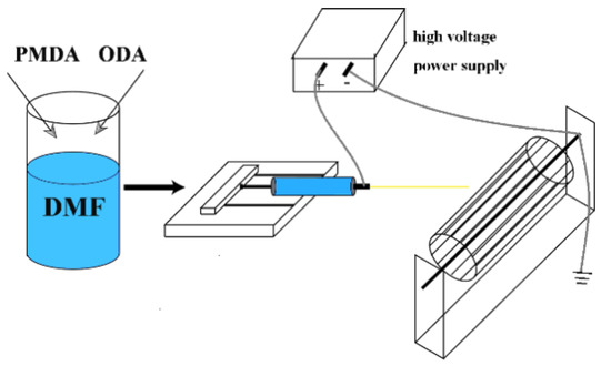
Figure 1.
Synthesis of polyamic acid (PAA) solution and the process of electrospinning.
2.3. Synthesis of the PI/TiO2 Nanofibers
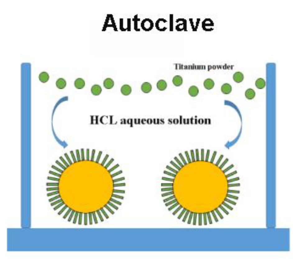
In the hydrothermal reaction autoclave, 33 mL water solution with 1 mol/L hydrochloric acid was added, then 0.04~0.05 g of titanium powders was added; finally, the polyimide fibers (0.1 g) were added. We then sealed it and set it aside for 3 h. The reaction kettle was put into the oven, heated to 160 °C, and reacted for 16 h. After the reaction, we removed the product, washed it with deionized water, and dried it at 60 °C.
2.4. Synthesis of the PI/TiO2@MoS2 Nanofibers
A small amount of sodium molybdate and thioacetamide was added to the deionized water, and the solution was stirred and put into to the hydrothermal reaction autoclave. The PI/TiO2 fibers were then added into the autoclave reactor; the autoclave reactor was sealed and put it in the oven heated to 200 °C and left to react for 24 h. Then, the product of the reaction was washed with deionized water several times and put in the oven at 60 °C to dry.
2.5. Characterization
The morphologies of the as-obtained samples were observed using field-emission scanning electron microscopy (FE-SEM, Carl Zeiss Merlin Compact and Hitachi S4800). The crystal structure of the products was characterized by X-ray diffraction (XRD, Bruker D8 Advance diffractometer) using CuKa1 radiation (λ = 0.15406 nm). UV–Vis absorption spectra were obtained using a UV–Vis spectrophotometer (UV-3600, Shimadzu, Japan). FTIR spectra were recorded on a Varian 670-IR spectrometer. The UV lamp was from Shanghai Guanghao ZF-2 (365 nm). The UV–Vis diffuse reflectance spectra (DRS) were recorded using UV–V is spectrophotometer (V-650.Jasco). X-ray photoelectron spectroscopy (XPS) measurements were carried out with an ESCALAB 250 Xi photoelectron spectrometer using Al Ka radiation (ThermoFisher Scientific, Waltham, MA, USA).
3. Results and Discussion
3.1. Characterization of the As-Prepared Photocatalysts
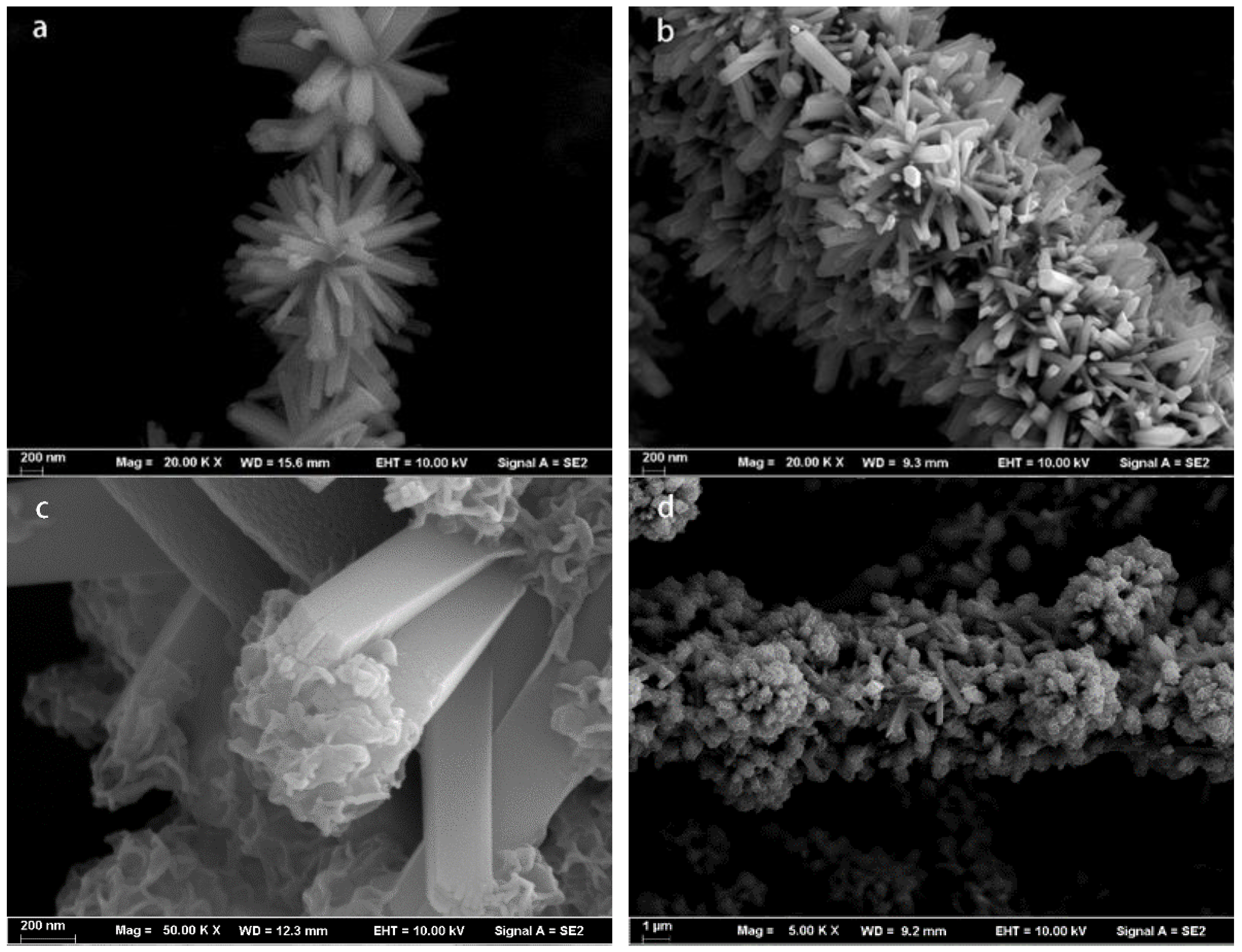
The morphology and nanostructure of the PI nanofibers were characterized by field-emission scanning electron microscopy (FESEM) observations (Figure 2). The surface morphology of the rod-like TiO2 with a length ranging from 800 to 1000 nm and a width ranging from 50 to 200 nm could be clearly observed, as shown in Figure 3a,b. From the figure, we can see that the TiO2 nanorods were very dense in the distribution of polyimide fibers. Figure 3c,d show that MoS2 nanospheres were grown in situ on the surface of the TiO2 nanorods. We can see that the MoS2 nanospheres were evenly distributed on the surface of TiO2 nanorods, which notably increased the specific surface area.
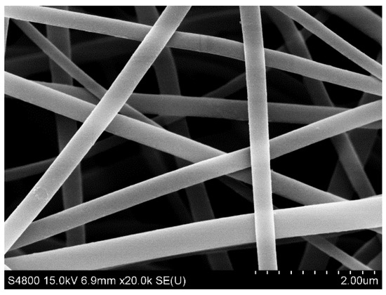
Figure 2.
FESEM images of PI nanofibers.

Figure 3.
FESEM images of PI/TiO2 nanocomposites (a,b) and PI/TiO2@MoS2 nanocomposites (c,d).
The PI/TiO2@MoS2 nanocomposite was characterized by powder X-ray diffraction (XRD), as shown in Figure 4. Strong XRD diffraction peaks at 2θ = 27.45°, 36.09°, 41.23°, 54.32°, 56.64°, and 69.01° were clearly observed, consistent with the (110), (101), (111), (211), (220), and (301) faces, respectively, of rutile phase TiO2 indexed to the JCPDS card 21-1276 with a space group of P42/mnm (a = b = 4.593Å and c = 2.959Å), similar to the standard spectrum of rutile TiO2. The hexagonal phase MoS2 was clearly shown. The diffraction weak peaks could be assigned to the (002), (100), and (110) planes in the hexagonal phase MoS2 (a = b = 0.316 nm, c = 1.230 nm, JCPDS card no. 37-1492), consistent with the findings of previous studies [33].
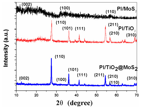
Figure 4.
XRD pattern of the as-prepared PI/MoS2, PI/TiO2 and PI/TiO2@ MoS2. 2θ.
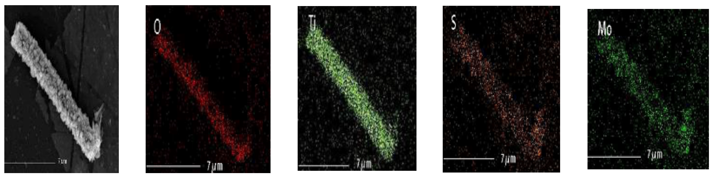
To further confirm the surface layer was MoS2, energy dispersive X-ray spectrometry (EDS) mapping (Figure 5) analysis of the PI/TiO2@ MoS2 nanocomposites was conducted. The EDS pattern of the TiO2@MoS2 nanorods heterostructures showed that the product nanorods were composed of Ti, O, Mo, and S. The EDS elemental mapping supports our argument that the outer layer was MoS2 nanosheets and the inner layer was TiO2 nanorods. The above experimental results proved that only a few layers of MoS2 were wrapped on the surface of the ultrafine TiO2 nanobelts to form TiO2@MoS2 nanorod heterostructures.
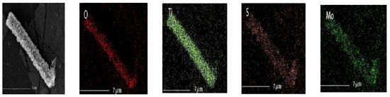
Figure 5.
EDS mapping results from PI/TiO2@MoS2.
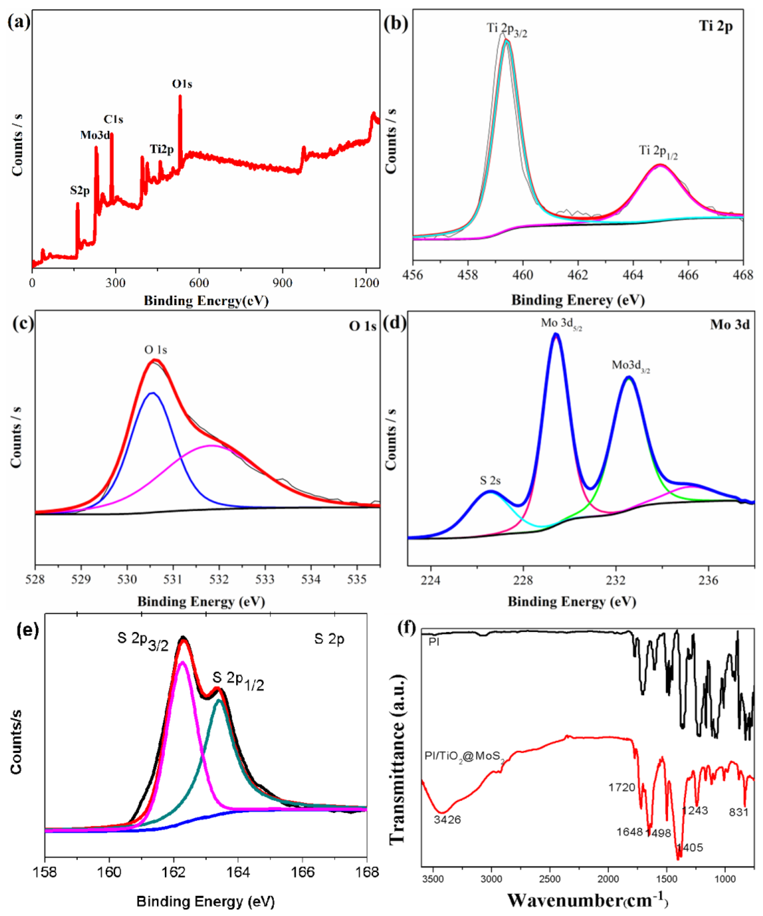
The chemical composition and valence state were characterized by X-ray photoelectron spectroscopy (XPS). The full-range XPS spectra of PI/TiO2@MoS2 (0–1050 eV) are shown in Figure 6a. Figure 6b shows that the binding energies (BE) of Ti 2p3/2 and Ti 2p1/2 were 459.3 and 464.7 eV, respectively, which we ascribed to the Ti4+ oxidation state. In Figure 6c, O1s is shown, and it is useful for identifying the core levels. In Figure 6d, the high-resolution XPS spectra show that the binding energy of Mo 3d3/2 and Mo 3d5/2 peaks in the TiO2@MoS2 heterostructures located at 229.5 and 232.8 eV, respectively, indicating that the Mo element was present in the Mo4+ chemical state. Figure 6e shows that the binding energies of S 2p3/2 and S 2p1/2 were 162.3 and 163.8 eV, respectively. By comparison to the NIST X-ray Photoelectron Spectroscopy Database, we identified the S element corresponding to producing the material for MoS2.
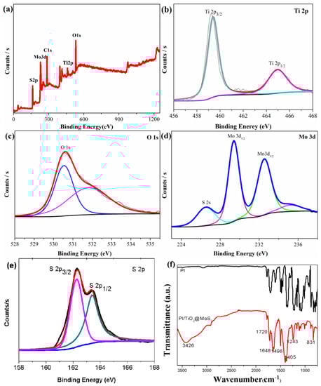
Figure 6.
(a) XPS spectrum of PI/TiO2@MoS2 composite; (b–e) high-resolution XPS spectra of Ti2p, O1s, Mo3d, and S2p; (f) FT-IR spectra of the nanocomposite.
PAA was analyzed in our previous report [34]. The FTIR of PI is shown without the –OH peak in Figure 6f. The PI/TiO2 nanorods showed bands around 3426 and 1648 cm−1, corresponding to the stretching and bending vibrations of hydroxyl groups on the surface of the TiO2 nanorod surface, respectively (Figure 6f). The strong absorption band between 800 and 400 cm−1 was attributed to the Ti-O and Ti-O-Ti vibrations. The strong characteristic absorption peaks at 3426, 1720, 1648, and 1498 cm−1 in Figure 6f also indicated the presence of amide groups, while the absorption peak at 1648 cm−1 represented the tertiary amide, which indicated that imidization was completed. The peaks at 1405 and 725 cm−1 corresponded to the asymmetric stretching vibration of C–N and the deformation of the imide ring, respectively, which create the characteristic peaks of polyimide groups. The bands near 1648 and 1117 cm−1 were also assigned to the Ti-O and Ti-O-C stretching modes, respectively. The FTIR results indicated that the TiO2 nanoparticles were successfully coated on the polyimide matrix. In MoS2, FTIR peaks exist in the range from 1008 to 1648, 2925, and 3426 cm−1. The strong O-H peak and water bonding are indicated by 3426 and 603 cm−1, respectively. The peaks situated at 1008 and 1243 cm−1 occurred due to the formation of complex sulfur with the active sites in MoS2.
To evaluate the effects of MoS2 nanoparticles onto the TiO2 nanorod support on the optical properties of PI/TiO2@MoS2 nanocomposite, UV–Vis diffuse absorbance spectra (DRS) analysis was performed. Figure 7a shows the corresponding UV–Vis DRS spectra for the PI/TiO2@MoS2 samples. The absorption thresholds for the samples were obtained from the UV–Vis DRS curves by extrapolating the tangent lies of the spectra. In general, bare TiO2 nanoparticles show absorption in the UV region without any absorption in the visible range owing to its wide band gap (~3.2 eV). As shown in Figure 7a, the threshold wavelength for the synthesized PI/TiO2@MoS2 sample is about 450 nm. Compared with pure TiO2, a red shift in the absorption edges toward the visible region was observed in the nanocomposite. This was induced by the strong optical absorption of black MoS2 in the visible-light region, which illustrated that there were interactions between TiO2 and MoS2 on the interface. The band gap energies (Eg) of the samples were calculated using the equation (A)2 = K(−Eg), where is the energy of a photon (eV), A is the absorption coefficient, K is a constant, and Eg is the band gap. The band gap was calculated by extrapolating the linear part of the spectra in a diagram of (A)2 versus the photon energy (Figure 7b). The band gap energy value for the PI/TiO2@MoS2 nanocomposite was calculated as 2.7 eV, implying that MoS2 nanospheres on a TiO2 nanorod support decreased the optical band gap energy. Therefore, the electron–hole separation was relatively better in the PI/TiO2@MoS2 nanocomposite.
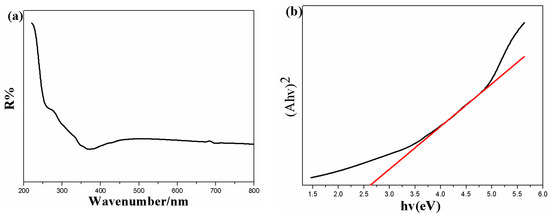
Figure 7.
(a) UV–Vis DRS absorbance spectra and (b) plot of (Ahν)2 versus hν for the samples.
3.2. Photocatalytic Activity the As-Prepared Photocatalysts
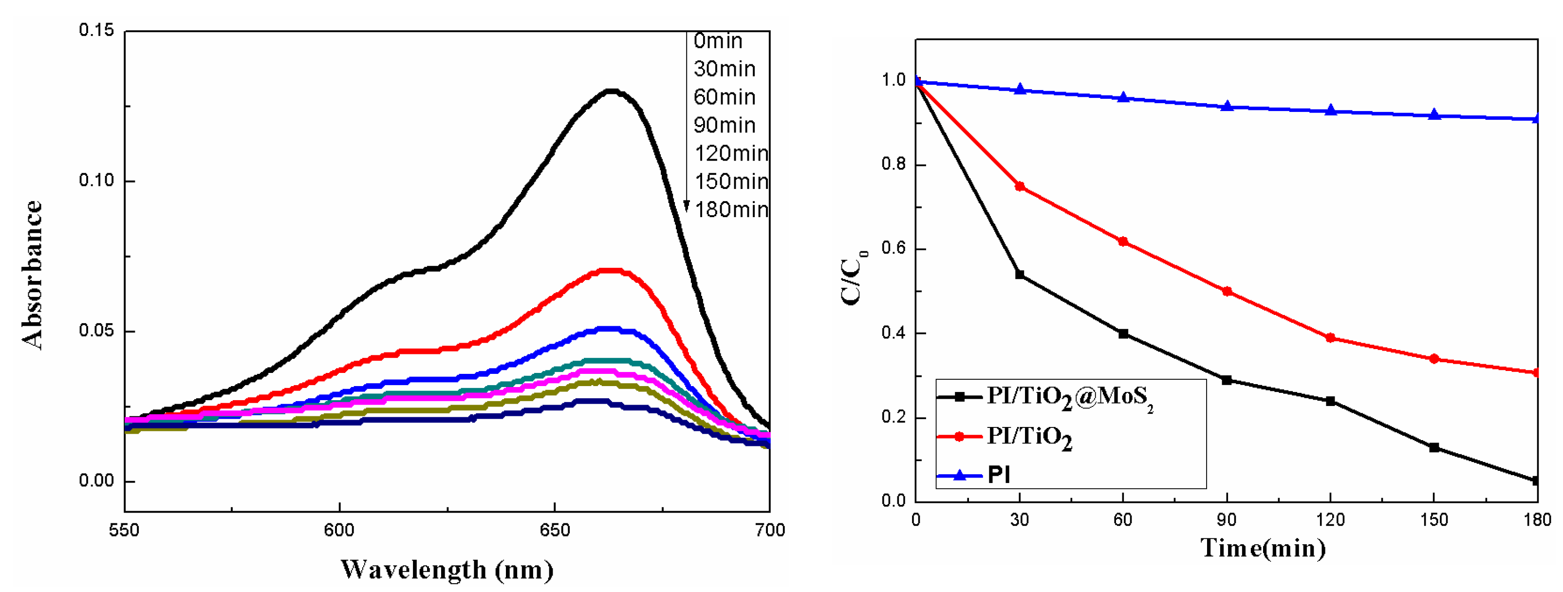
The photocatalytic performance of PI/TiO2@MoS2 was evaluated for the photodegradation of methylene blue (MB) at room temperature. The decay of the characteristic absorption peak of MB at 663 nm was followed every 30 min by UV–Vis spectrophotometry. Before UV exposure, the solution was kept in the dark for 30 min to build the adsorption/desorption equilibrium between the dye and surface. We found a gradual decrease in the main absorption peak, because of the adsorption of MB molecules on the surface of the sample. Usually, it is difficult to degrade pure MB and PI nanofiber in UV [35,36]. Figure 8 (left) shows the UV–Vis spectra of MB (5 mg/L) after ultraviolet light (λ = 365 nm) irradiation in the presence of PI/TiO2@MoS2 (0.02 g). With increasing irradiation time, the intensity of the characteristic absorption band of MB at 663 nm markedly reduced. In the meantime, the color of the solution changed, turning from blue to colorless after 180 min with irradiation, thus indicating the gradual decomposition of MB molecules during ultraviolet-light irradiation. The degradation efficiency is reported as C/C0, where C is the absorption of the main peak at 663 nm of MB at time t, and C0 corresponds to the initial concentration (after achievement of adsorption/desorption equilibrium (30 min)). As shown in Figure 8 (right), we observed that the dye degradation rate of the prepared samples varied with the same irradiation rate of UV at the same time. The results showed that PI/TiO2@MoS2 composites showed enhanced photocatalytic activity compared with PI/TiO2 for the degradation of methylene blue under UV irradiation. The PI/TiO2@MoS2 composites decomposed about 95% methylene blue within 180 min under UV irradiation. Compared with a single PI/TiO2 composite fiber or PAN nanofibers with MoS2-TiO2 surface-loaded by vacuum filtration [37], a certain amount of molybdenum dioxide increased the efficiency of photodegradation. It may promote the light absorption efficiency of TiO2 particles that decreases the electron–hole recombination and enhances the photogenerated charge separation.
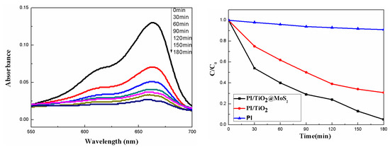
Figure 8.
UV–Vis absorption spectra of methylene blue (MB) as a function of UV-light irradiation time (λ = 365 nm) in the presence of the PI/TiO2@MoS2 composites fiber (left); MB concentration changes with the as-prepared samples (right).
3.3. Possible Mechanism of the Experiment
Figure 9 shows a schematic diagram of the formation mechanism of TiO2 nanorods by the “dissolve and grow” progress, which we describe using the following chemical reaction:

Figure 9.
Schematic diagram of the formation mechanism of TiO2 nanorods.
At the beginning, Ti powders react with H+ at high temperature and gradually dissolve in the solution of HCL, continuously releasing the Ti(III) precursors into the reaction solution. Due to the instability of Ti(III) in aqueous solution, Ti(III) is hydrolyzed to TiOH2+. According to Fujihara et al. [38], TiOH2+ is oxidized to Ti(IV) by reacting with dissolved oxygen. Therefore, the formation mechanism of rutile TiO2 nanorods using Ti(IV) complex ions as growth units can be described as follows: For rutile TiO2, TiO6 octahedra are first formed by bonding Ti atoms and six oxygen atoms. Then, the TiO2 octahedron shares a couple of opposite edges with the next octahedron, forming a catenarian structure. The growth of rutile nanorods follows the sequence (110) < (100) < (101) < (001), because the growth rate of different crystal planes depends on the number of coordinated polygon body corners and edges. Therefore, rutile TiO2 nanorods grown in the [001] direction were formed [39,40].
According to the previous experimental results, a promotional mechanism is shown in Figure 10. Under UV-light irradiation, TiO2 absorbs photons and creates electron–hole pairs. Because the conduction band (CB) of TiO2 is higher than that of MoS2 [41,42,43], the photoelectrons generated by CB of TiO2 are easily transferred to MoS2, which improves the separation of photogenerated electron–hole pairs and enhances the photocatalytic activity of PI/TiO2@MoS2 heterostructures. The separated electrons react with dissolved O2 to produce O2.− radicals on the surface of MoS2 nanosheets. Next, they combine with H+ to produce H2O2, and finally decompose into ·OH. In the meantime, the cumulative holes on the surface of TiO2 are trapped by OH– or H2O to form hydroxyl radicals, ·OH. Finally, the oxidation of organic dyes mainly occurs due to the involvement of holes, ·OH, and O2.− radicals. The main reactions in our study are described by equations:
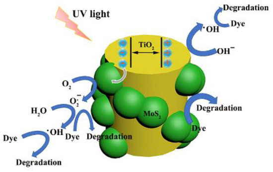
Figure 10.
Assumed mechanism of the photodegradation of dyes with PI/TiO2@MoS2 heterostructures.
4. Conclusions
PI/TiO2@MoS2 heterostructures were successfully fabricated by the assembly of MoS2 nanosheets and TiO2 nanorods on electrospun polyimide nanofibers using a simple hydrothermal method. Our innovation is in the successful structure of nanofiber–nanorod–nanosheet multilevel nanostructure of PI/TiO2@MoS2 composite fibers. Compared with the usual nanoparticles on the surface of electrospun nanofibers, the functionalized application of composite nanofibers is expected. In this study, nanocomposite fibers with a multistage structure were proposed, which improves the performance of a single composite and can realize various functional applications. This multistage structure not only improves photocatalytic performance, but also the choice of gas adsorption, gas separation, supercapacitors, bi-sensing, etc. These nanocomposite fibers will have a wide range of applications, which is our next research direction.
Author Contributions
Conceptualization, Z.C. and J.H.; Preparation of samples, data curation, formal analysis, investigation, and writing— original draft, J.H., X.S. and Z.L.; Writing—review & editing, Z.C. and Q.L. All authors have read and agreed to the published version of the manuscript.
Funding
The authors gratefully acknowledge the financial support received from the National Natural Science Foundation of China (No. 51203068). This project was funded by the Priority Academic Program Development of Jiangsu Higher Education Institutions (PAPD).
Institutional Review Board Statement
Not applicable.
Informed Consent Statement
Not applicable.
Data Availability Statement
The data presented in this study are available on request from the corresponding author.
Conflicts of Interest
The authors declare no conflict of interest.
References
- Yan, M.; Hua, Y.Q.; Zhu, F.F.; Gu, W.; Jiang, J.H.; Shen, H.Q.; Shi, W.D. Fabrication of nitrogen doped graphene quantum dots-BiOI/MnNb2O6 p-n junction photocatalysts with enhanced visible light efficiency in photocatalytic degradation of antibiotics. Appl. Catal. B 2017, 202, 518–527. [Google Scholar] [CrossRef]
- Zhang, N.; Yang, M.Q.; Liu, S.Q.; Sun, Y.G.; Xu, Y.J. Waltzing with the versatile platform of graphene to synthesize composite photocatalysts. Chem. Rev. 2015, 115, 10307–10377. [Google Scholar] [CrossRef] [PubMed]
- Sun, M.H.; Huang, S.Z.; Chen, L.H.; Li, Y.; Yang, X.Y.; Yuan, Z.Y.; Su, B.L. Applications of hierarchically structured porous materials from energy storage and conversion, catalysis, photocatalysis, adsorption, separation, and sensing to biomedicine. Chem. Soc. Rev. 2016, 45, 3479–3563. [Google Scholar] [CrossRef]
- Li, X.; Yu, J.G.; Jaroniec, M. Hierarchical photocatalysts. Chem. Soc. Rev. 2016, 45, 2603–2636. [Google Scholar] [CrossRef] [PubMed]
- Bagheri, S.; Yousefia, A.T.; Do, T.O. Photocatalytic pathway toward degradation of environmental pharmaceutical pollutants: Structure, kinetics and mechanism approach. Catal. Sci. Technol. 2017, 7, 4548–4569. [Google Scholar] [CrossRef]
- Lu, F.; Wang, J.; Chang, Z.; Zeng, J. Uniform deposition of Ag nanoparticles on ZnO nanorod arrays grown on polyimide/Ag nanofibers by electrospinning, hydrothermal, and photoreduction processes. Mater. Des. 2019, 181, 108069. [Google Scholar] [CrossRef]
- He, T.; Zhou, Z.; Xu, W.; Cao, Y.; Shi, Z.; Pan, W.P. Visible-light photocatalytic activity of semiconductor composites supported by electrospun fiber. Compos. Sci. Tech. 2010, 70, 1469–1475. [Google Scholar] [CrossRef]
- Zhao, S.; Li, J.; Wang, L.; Wang, X. Degradation of Rhodamine B and Safranin-T by MoO3: CeO2 Nanofibers and Air Using a Continuous Mode. CLEAN-Soil Air Water 2010, 38, 268–274. [Google Scholar] [CrossRef]
- Xu, H.; Ouyang, S.; Liu, L.; Reunchan, P.; Umezawa, N.; Ye, J. Recent advances in TiO2-based photocatalysis. J. Mater. Chem. A 2014, 2, 12642–12661. [Google Scholar] [CrossRef]
- Leong, S.; Razmjou, A.; Wang, K.; Hapgood, K.; Zhang, X.; Wang, H. TiO2 based photocatalytic membranes: A review. J. Membr. Sci. 2014, 472, 167–184. [Google Scholar] [CrossRef]
- Montes-Navajas, P.; Serra, M.; Corma, A.; Garcia, H. Contrasting photocatalytic activity of commercial TiO2 samples for hydrogen generation. Catal. Today 2014, 225, 52–54. [Google Scholar] [CrossRef]
- Ni, M.; Leung, M.K.H.; Leung, D.Y.C.; Sumathy, K. A review and recent developments in photocatalytic water-splitting using TiO2 for hydrogen production. Renew. Sustain. Energy Rev. 2007, 11, 401–425. [Google Scholar] [CrossRef]
- Rather, S.U.; Mehraj-ud-din, N.; Zacharia, R.; Hwang, S.W.; Kim, A.R.; Nahm, K.S. Hydrogen storage of nanostructured TiO2-impregnated carbon nanotubes. Int. J. Hydrog. Energy 2009, 34, 961–966. [Google Scholar] [CrossRef]
- Chen, H.; Nanayakkara, C.E.; Grassian, V.H. Titanium dioxide photocatalysis in atmospheric chemistry. Chem. Rev. 2012, 112, 5919–5948. [Google Scholar] [CrossRef]
- Hashimoto, K.; Irie, H.; Fujishima, A. TiO2 photocatalysis: A historical overview and future prospects. AAPPS Bull. 2007, 17, 12–28. [Google Scholar]
- Pelaez, M.; Nolan, N.T.; Pillai, S.C.; Seery, M.K.; Falaras, P.; Kontos, A.G.; Dunlop, P.S.M.; Hamilton, J.W.J.; Byrne, J.A.; O’Sheaf, K.; et al. A review on the visible light active titanium dioxide photocatalysts for environmental applications. Appl. Catal. B 2012, 125, 331–349. [Google Scholar] [CrossRef] [Green Version]
- Fujishima, A.; Honda, K. Electrochemical photolysis of water at a semiconductor electrode. Nature 1972, 238, 37–38. [Google Scholar] [CrossRef]
- Roy, N.; Sohn, Y.; Pradhan, D. Synergy of Low-Energy {101} and High-Energy {001} TiO2 Crystal Facets for Enhanced Photocatalysis. ACS Nano 2013, 7, 2532–2540. [Google Scholar] [CrossRef] [PubMed]
- Deokar, G.; Vancsó, P.; Arenal, R.; Ravaux, F.; Casanova-Cháfer, J.; Llobet, E.; Makarova, A.; Vyalikh, D.; Struzzi, C.; Lambin, P.; et al. MoS2–Carbon Nanotube Hybrid Material Growth and Gas Sensing. Adv. Mater. Interfaces 2017, 4, 1700801. [Google Scholar] [CrossRef]
- Chang, K.; Mei, Z.M.; Wang, T.; Kang, Q.; Ouyang, S.X.; Ye, J.H. MoS2/Graphene Cocatalyst for Efficient Photocatalytic H2 Evolution under Visible Light Irradiation. ACS Nano 2014, 8, 7078–7087. [Google Scholar] [CrossRef] [PubMed]
- Kong, D.; Wang, H.; Cha, J.J.; Pasta, M.; Koski, K.J.; Yao, J.; Cui, Y. Synthesis of MoS2 and MoSe2 Films with Vertically Aligned Layers. Nano Lett. 2013, 13, 1341–1347. [Google Scholar] [CrossRef] [PubMed]
- Liu, Y.; Niu, H.; Gu, W.; Cai, X.; Mao, B.; Li, D.; Shi, W. In-situ construction of hierarchical CdS/MoS2 microboxes for enhanced visible-light photocatalytic H2 production. Chem. Eng. J. 2018, 339, 117–124. [Google Scholar] [CrossRef]
- Liu, Y.; Yu, Y.X.; Zhang, W.D. MoS2/CdS Heterojunction with High Photoelectrochemical Activity for H2 Evolution under Visible Light: The Role of MoS2. J. Phys. Chem. C 2013, 117, 12949–12957. [Google Scholar] [CrossRef]
- Jia, T.; Kolpin, A.; Ma, C.; Chan, R.C.; Kwok, W.M.; Tsang, S.C. A graphene dispersed CdS–MoS2 nanocrystal ensemble for cooperative photocatalytic hydrogen production from water. Chem. Commun. 2014, 50, 1185–1188. [Google Scholar] [CrossRef] [PubMed]
- Li, Q.; Zhang, N.; Yang, Y.; Wang, G.Z. High Efficiency Photocatalysis for Pollutant Degradation with MoS2/C3N4 Heterostructures. Langmuir 2014, 30, 8965–8972. [Google Scholar] [CrossRef] [PubMed]
- Wang, X.; Hong, M.Z.; Zhang, F.W.; Zhuang, Z.Y.; Yu, Y. Recyclable Nanoscale Zero Valent Iron Doped g-C3N4/MoS2 for Efficient Photocatalysis of RhB and Cr(VI) Driven by Visible Light. ACS Sustain. Chem. Eng. 2016, 4, 4055–4063. [Google Scholar] [CrossRef]
- Tian, N.; Li, Z.; Xu, D.Y.; Li, Y.; Peng, W.C.; Zhang, G.L.; Zhang, F.B.; Fan, X.B. Utilization of MoS2 Nanosheets To Enhance the Photocatalytic Activity of ZnO for the Aerobic Oxidation of Benzyl Halides under Visible Light. Ind. Eng. Chem. Res. 2016, 55, 8726–8732. [Google Scholar] [CrossRef]
- Zhang, C.M.; Chen, G.; Li, C.M.; Sun, J.X.; Lv, C.D.; Fan, S.; Xing, W.N. In Situ Fabrication of Bi2WO6/MoS2/RGO Heterojunction with Nanosized Interfacial Contact via Confined Space Effect toward Enhanced Photocatalytic Properties. ACS Sustain. Chem. Eng. 2016, 4, 5936–5942. [Google Scholar] [CrossRef]
- Wei, L.; Chen, Y.; Lin, Y.; Wu, H.; Yuan, R.; Li, Z. MoS2 as non-noble-metal co-catalyst for photocatalytic hydrogen evolution over hexagonal ZnIn2S4 under visible light irradiations. Appl. Catal. B 2014, 144, 521–527. [Google Scholar] [CrossRef]
- Jiang, J.; Carlson, M.A.; Teusink, M.J.; Wang, H.J.; MacEwan, M.R.; Xie, J.W. Expanding two-dimensional electrospun nanofiber membranes in the third dimension by a modified gas-foaming technique. ACS Biomater. Sci. Eng. 2015, 1, 991–1001. [Google Scholar] [CrossRef] [PubMed]
- Vanangamudi, A.; Dumee, L.F.; Duke, M.C.; Yang, X. Nanofiber composite membrane with intrinsic Janus surface for reversed-protein-fouling ultrafiltration. ACS Appl. Mater. Interfaces 2017, 9, 18328–18337. [Google Scholar] [CrossRef] [PubMed]
- Kristopher, W.; Dobosz Kolewe, K.M.K.; Rieger, A.; Chang, C.; Emrick, T.; Schiffman, J.D. Antifouling electrospun nanofiber mats functionalized with polymer zwitterions. ACS Appl. Mater. Interfaces 2016, 8, 27585–27593. [Google Scholar]
- Li, H.; Wang, Y.; Chen, G.; Sang, Y.; Jiang, H.; He, J.; Liu, H. Few-layered MoS2 nanosheets wrapped ultrafine TiO2 nanobelts with enhanced photocatalytic property. Nanoscale 2016, 8, 6101–6109. [Google Scholar] [CrossRef]
- Chang, Z.; Zeng, J. Immobilization seeding layers using precursor for fabricating core–shell polyimide/Cu–BTC hierarchical nanofibers with high gas separation and adsorption of methylene blue from aqueous solution. Macromol. Chem. Phys. 2016, 217, 1007–1013. [Google Scholar] [CrossRef]
- Ramasundaram, S.; Seid, M.G.; Lee, W.; Kim, C.U.; Kim, E.J.; Hong, S.W.; Choi, K.J. Preparation, characterization, and application of TiO2-patterned polyimide film as a photocatalyst for oxidation of organic contaminants. J. Hazard. Mater. 2017, 340, 300–308. [Google Scholar] [CrossRef] [PubMed]
- Ma, C.; Zhou, Z.; Wei, H.; Yang, Z.; Wang, Z.; Zhang, Y. Rapid large-scale preparation of ZnO nanowires for photocatalytic application. Nanoscale Res. Lett. 2011, 6, 1–5. [Google Scholar] [CrossRef] [PubMed] [Green Version]
- Zhang, X.; Fu, K.; Su, Z. Fabrication of 3D MoS2-TiO2@ PAN electro-spun membrane for efficient and recyclable photocatalytic degradation of organic dyes. Mater. Sci. Eng. B 2021, 269, 115179. [Google Scholar] [CrossRef]
- Hosono, E.; Fujihara, S.; Kakiuchi, K.; Imai, H. Growth of Submicrometer-Scale Rectangular Parallelepiped Rutile TiO2 Films in Aqueous TiCl3 Solutions under Hydrothermal Conditions. J. Am. Chem. Soc. 2004, 126, 7790–7791. [Google Scholar] [CrossRef]
- Cheng, H.M.; Ma, J.M.; Zhao, Z.G.; Qi, L.M. Hydrothermal preparation of uniform nanosize rutile and anatase particles. Chem. Mater. 1995, 7, 663–671. [Google Scholar] [CrossRef]
- Kumar, A.; Madaria, A.R.; Zhou, C.W. Growth of Aligned Single-Crystalline Rutile TiO2 Nanowires on Arbitrary Substrates and Their Application in Dye-Sensitized Solar Cells. J. Phys. Chem. C 2010, 114, 7787–7792. [Google Scholar] [CrossRef]
- Zhang, X.; Shao, C.L.; Li, X.H.; Miao, F.J.; Wang, K.X.; Lu, N.; Liu, Y.C. 3D MoS2 nanosheet/TiO2 nanofiber heterostructures with enhanced photocatalytic activity under UV irradiation. J. Alloy.Compd. 2016, 686, 137–144. [Google Scholar] [CrossRef]
- Sonkusare, V.N.; Chaudhary, R.G.; Bhusari, G.S.; Mondal, A.; Potbhare, A.K.; Mishra, R.K.; Juneja, H.D.; Abdala, A.A. Mesoporous Octahedron-Shaped Tricobalt Tetroxide Nanoparticles for Photocatalytic Degradation of Toxic Dyes. ACS Omega 2020, 5, 7823–7835. [Google Scholar] [CrossRef] [PubMed]
- Zhao, C.Q.; Jing, T.; Dong, M.Y.; Pan, D.; Guo, J.; Tian, J.Z.; Wu, M.; Naik, N.; Huang, M.N.; Guo, Z.H. A Visible Light Driven Photoelectrochemical Chloramphenicol Aptasensor Based on a Gold Nanoparticle-Functionalized 3D Flower-like MoS2/TiO2 Heterostructure. Langmuir 2022, 38, 2276–2286. [Google Scholar] [CrossRef] [PubMed]


Publisher’s Note: MDPI stays neutral with regard to jurisdictional claims in published maps and institutional affiliations. |
© 2022 by the authors. Licensee MDPI, Basel, Switzerland. This article is an open access article distributed under the terms and conditions of the Creative Commons Attribution (CC BY) license (https://creativecommons.org/licenses/by/4.0/).