
Mitigation and Remediation Technologies of Waxy Crude Oils’ Deposition within Transportation Pipelines: A Review

 , , ,
, , , 
Abstract
:1. Introduction
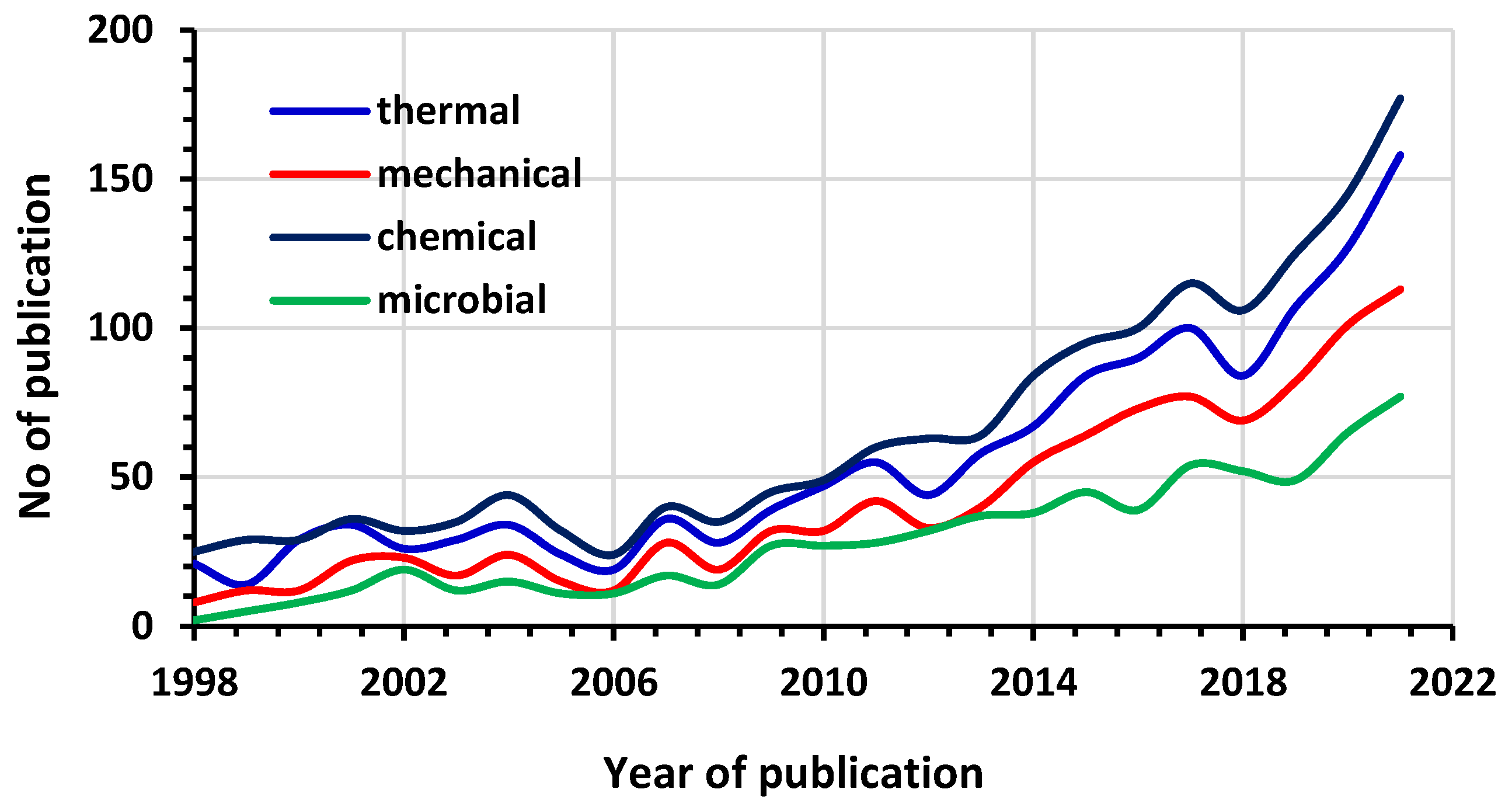
2. Wax Deposition Treatment Technologies
2.1. Prevention and Inhibition Methods
2.1.1. Thermal Methods
Insulation
Active Heating
2.1.2. Mechanical
Magnetic Application
Surface Treatment (Internal Coating)
2.1.3. Chemical Treatments
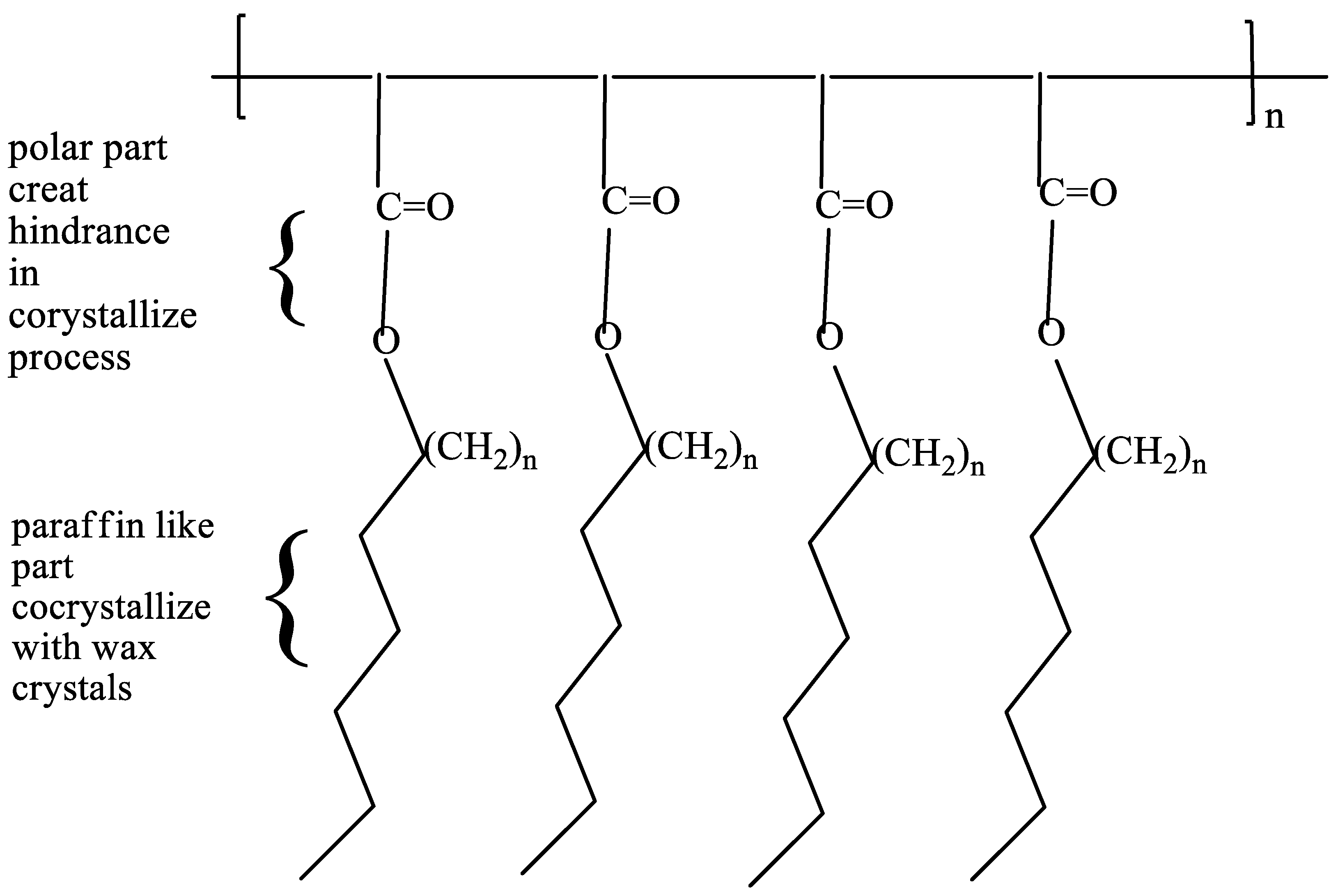
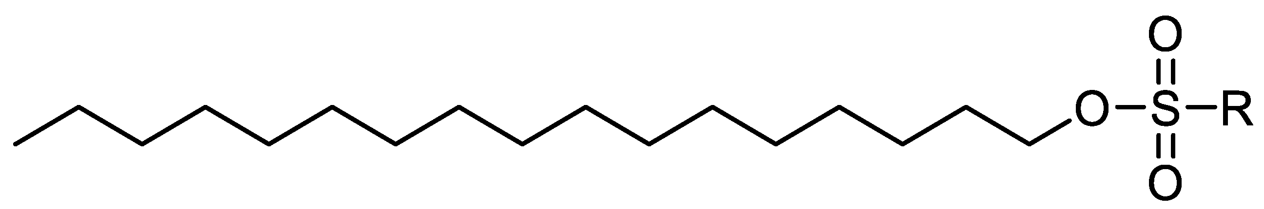
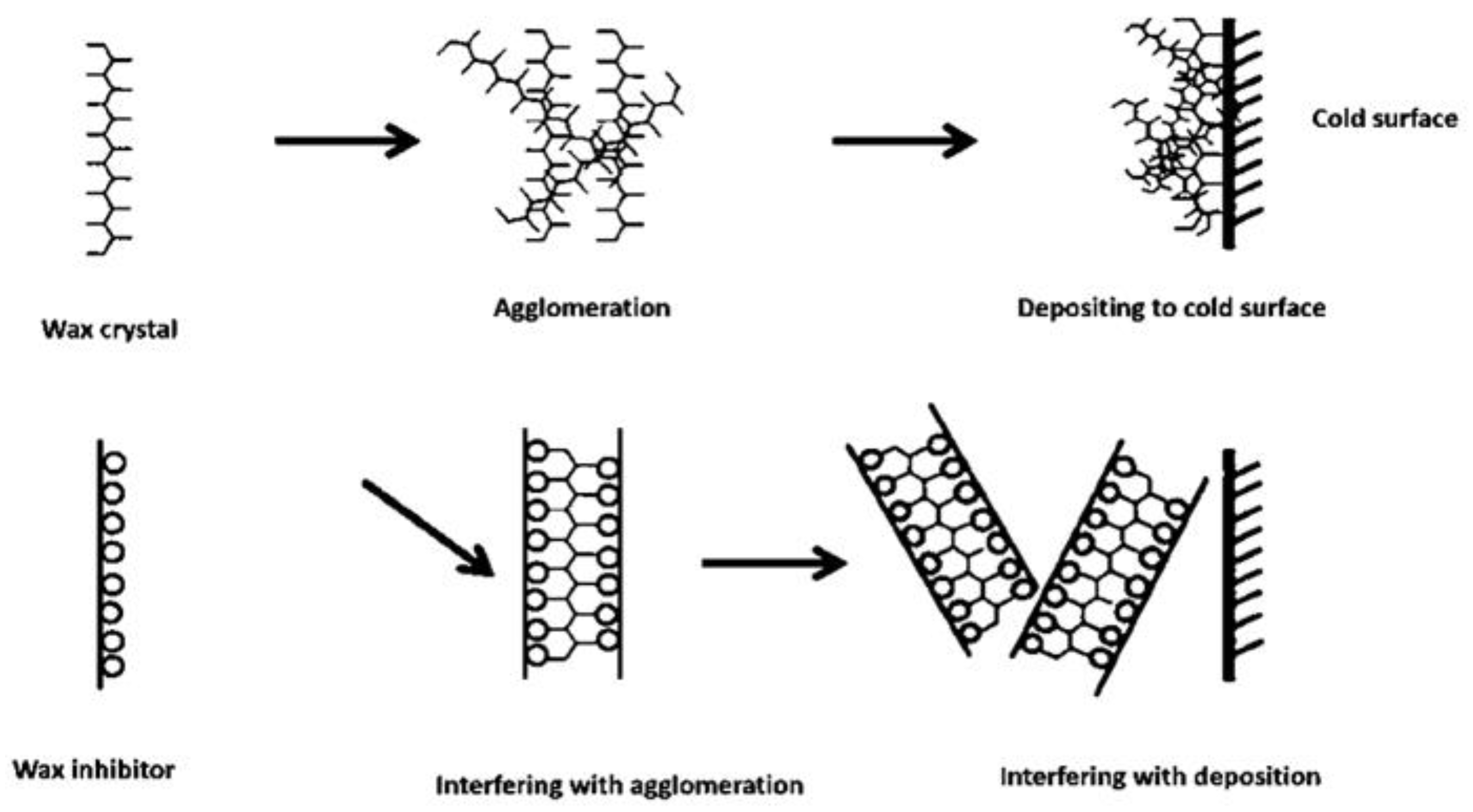
Wax Inhibitors or Pour Point Depressant
Types of Pour Point Depressants
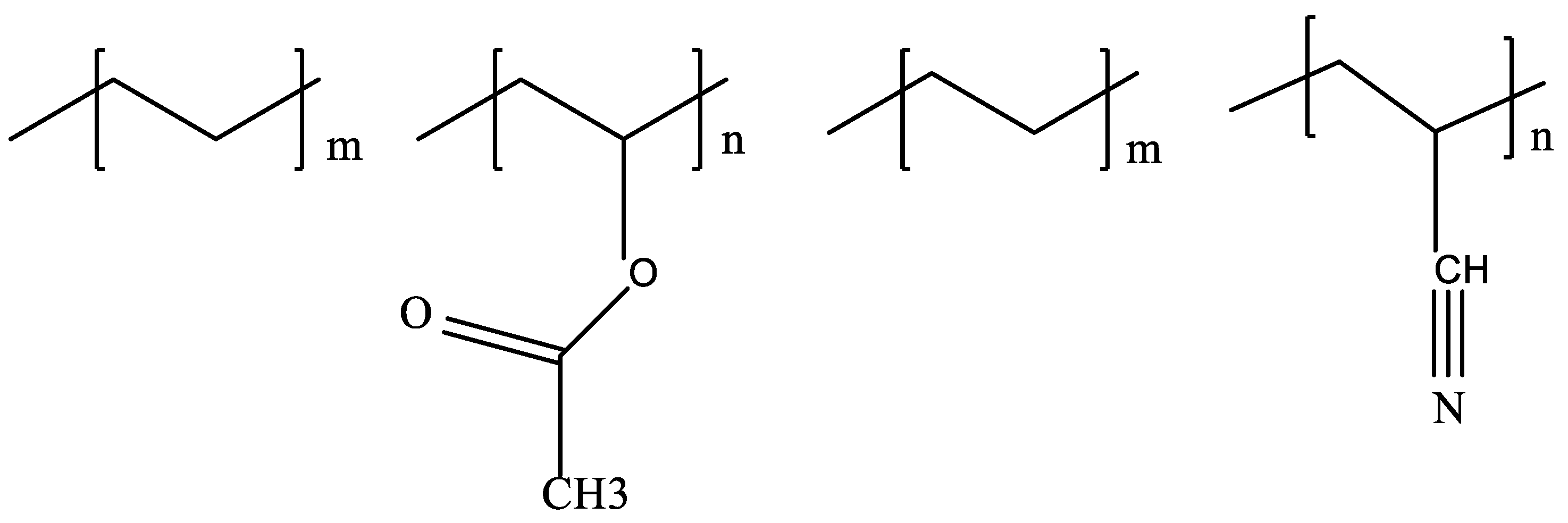
Ethylene Copolymers
Comb-Shaped Polymers
Maleic Anhydride-Based Copolymers
Drag Reducers
Nano-Heterogeneous
2.1.4. Biological Treatment
2.2. Removal Methods
2.2.1. Thermal
2.2.2. Mechanical
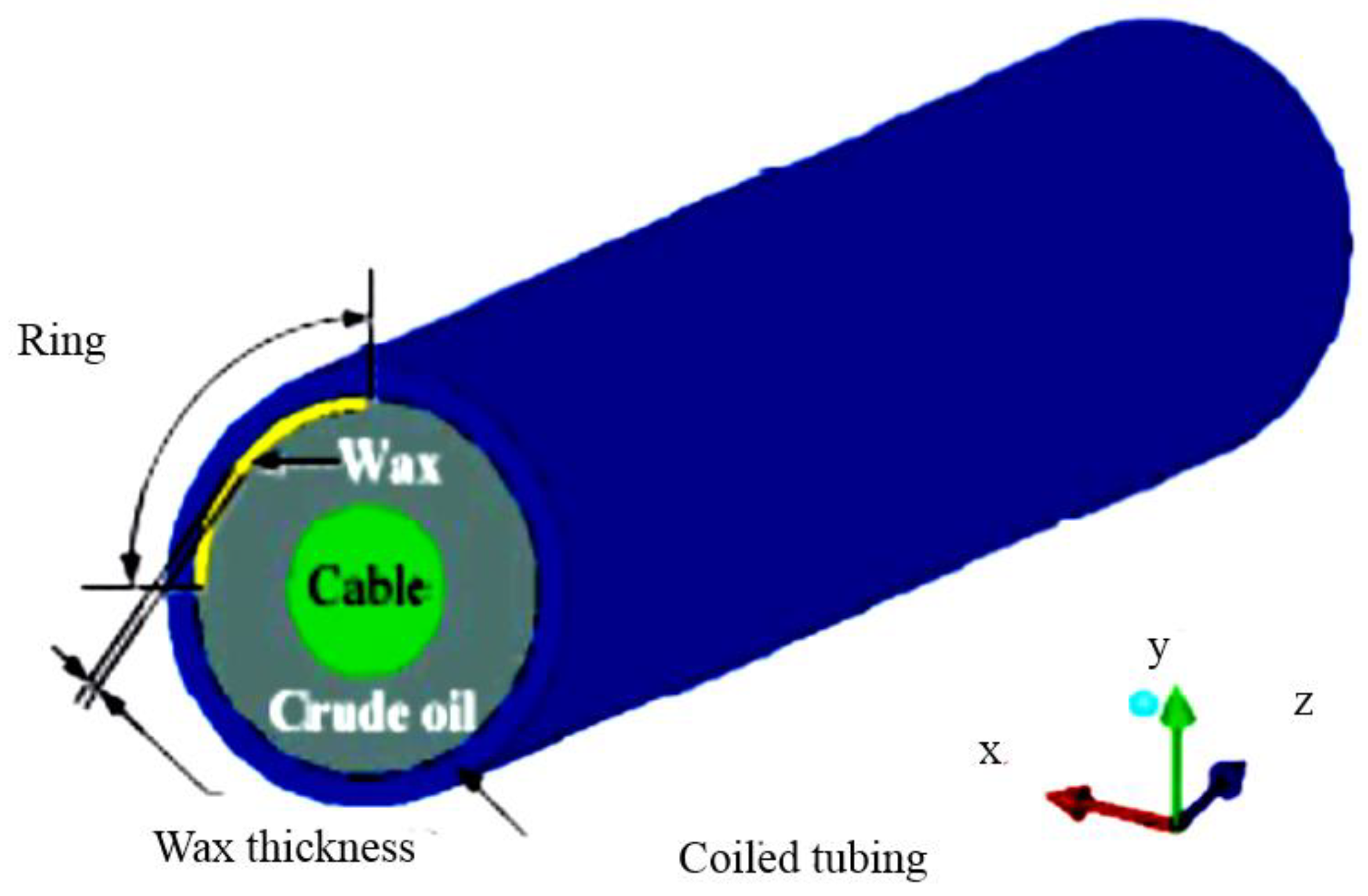
Coiled Tubing
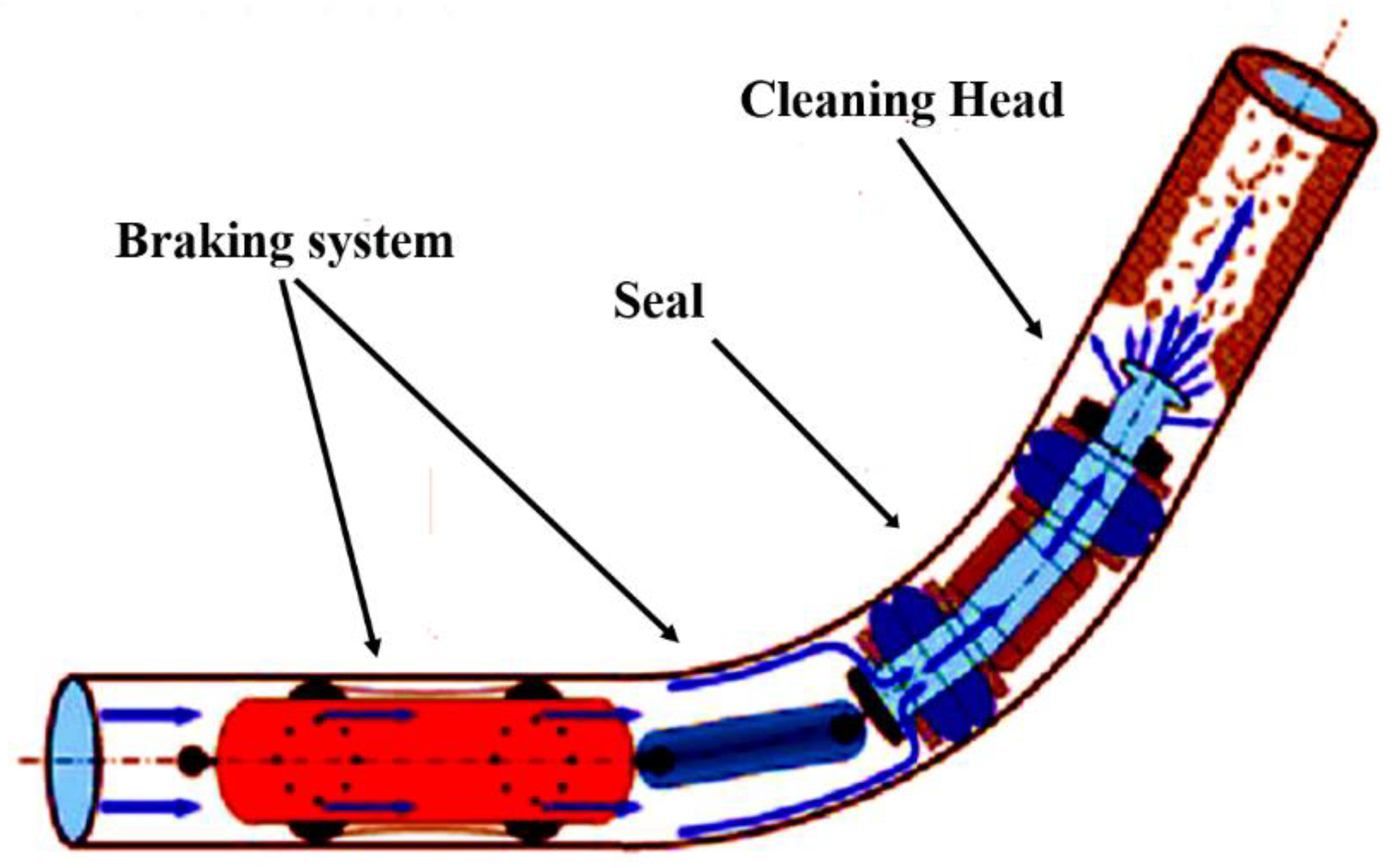
Pigging
- The size of pipe;
- The pipeline section length;
- The smallest bend radius used when building the line;
- The item travelling through the pipeline;
- How many I/D modifications resulting from changes in wall thickness are currently planned?
- Types of valve;
- Is the pipeline cross-country or subsea?
- Pig trap design;
- What debris is to be removed from the pipeline and pipe wall by the cleaning device?
Jet Cutting
2.2.3. Chemical
Solvent
Dispersants
2.2.4. Hybrid Treatment
Mechano-Chemical Treatments
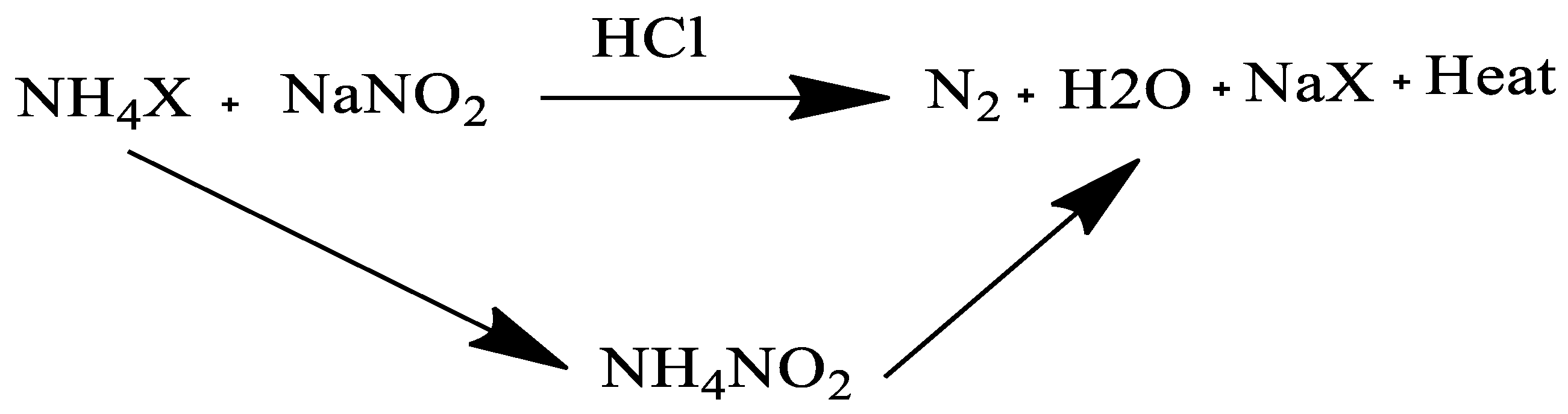
Thermo-Chemical Treatment
3. Conclusions
Author Contributions
Funding
Institutional Review Board Statement
Informed Consent Statement
Data Availability Statement
Conflicts of Interest
References
- Soliman, E.A.; Elkatory, M.R.; Hashem, A.I.; Ibrahim, H.S. Synthesis and performance of maleic anhydride copolymers with alkyl linoleate or tetra-esters as pour point depressants for waxy crude oil. Fuel 2018, 211, 535–547. [Google Scholar] [CrossRef]
- Soliman, E. Flow of heavy oils at low temperatures: Potential challenges and solutions. In Processing of Heavy Crude Oils-Challenges and Opportunities; Gounder, R.M., Ed.; Intech Open Limited: London, UK, 2019. [Google Scholar]
- Elkatory, M.; Soliman, E.; Hassaan, M.; Ali, R.; Hafez, E.; Ibrahim, H.S.; Hashem, A. Chemical mitigation technology for wax deposition in submarine oil pipeline systems. Egypt. J. Chem. 2021, 64, 5989–5997. [Google Scholar] [CrossRef]
- Turbakov, M.S.; Riabokon, E.P. Improving of Cleaning Efficiency of Oil Pipeline from Paraffin. In Proceedings of the SPE Russian Oil and Gas Exploration and Porudction Technical Conference and Exhibition, Moscow, Russia, 14–16 October 2014. [Google Scholar]
- Thota, S.T.; Onyeanuna, C.C. Mitigation of wax in oil pipelines. Int. J. Eng. Res. Rev. 2016, 4, 39–47. [Google Scholar]
- Sousa, A.L.; Matos, H.A.; Guerreiro, L.P. Preventing and removing wax deposition inside vertical wells: A review. J. Pet. Explor. Prod. Technol. 2019, 9, 2091–2107. [Google Scholar] [CrossRef]
- Persad, N.; Hosein, R.; Jupiter, A. A comparative analysis of two methods of wax treatment for a waxy oil in Southwest Trinidad. Petr. Sci. Technol. 2019, 37, 452–460. [Google Scholar] [CrossRef]
- Pahlavan, F.; Mousavi, M.; Hung, A.; Fini, E.H. Investigating molecular interactions and surface morphology of wax doped asphaltenes. Phys. Chem. Chem. Phys. 2016, 18, 8840–8854. [Google Scholar] [CrossRef]
- Ma, Q.; Liu, Y.; Lv, X.; Zhou, S.; Lu, Y.; Wang, C.; Gong, J. In situ record of the dynamic process of wax deposition in water-in-oil emulsion: Evolution of two types of deposition structures. J. Pet. Sci. Eng. 2022, 214, 110560. [Google Scholar] [CrossRef]
- Rehan, M.; Nizami, A.S.; Taylan, O.; Al-Sasi, B.O.; Demirbas, A. Determination of wax content in crude oil. Pet. Sci. Technol. 2016, 34, 799–804. [Google Scholar] [CrossRef]
- Al-Yaari, M.; Fahd, K. Paraffin wax deposition: Mitigation and removal techniques. In Proceedings of the SPE Saudi Arabia Section Young Professionals Technical Symposium, Dhahran, Saudi Arabia, 14–16 March 2011. OnePetro: SPE Saudi Arabia section Young Professionals Technical Symposium. [Google Scholar] [CrossRef]
- Li, Y.F.; Tsai, T.H.; Yang, T.H. A novel strengthening method for damaged pipeline under high temperature using inorganic insulation material and carbon fiber reinforced plastic composite material. Materials 2019, 12, 3484. [Google Scholar] [CrossRef] [Green Version]
- Bagdat, M.; Masoud, R. Control of paraffin deposition in production operation by using ethylene-tetrafluoroethylene (ETFE). In Proceedings of the International Conference on Integrated Petroleum Engineering and Geosciences (ICIPEG) 2014, Kuala Lumpur, Malaysia, 3–5 June 2014; pp. 13–22. [Google Scholar]
- Ye, Q.; Xian, L.; Zhang, F.; Yu, H.; Li, X. Research on influence of wax deposition on flow state in coiled tubing with cable inside. AIP Conf. Proc. 1955, 2018, 030045. [Google Scholar]
- Bosh, F.G.; Eastlund, B.J. Evaluation of downhole electric impedance heating systems for paraffin control in oil wells. IEEE Trans. Ind. Appl. 1992, 28, 190–195. [Google Scholar] [CrossRef]
- Guerreiro, L.; Carvalho, A.; Maciel, C.; Sousa, J.; Caetano, H.; Soares, L.; Carneiro, S.; Castanho, S.; Machado, V. The challenge of developing complex marginal fields, example of NE Brazil. In Proceedings of the Abu Dhabi International Petroleum Conference and Exhibition, Abu Dhabi, United Arab Emirates, 11–14 November 2012. [Google Scholar]
- Sunday, N.; Settar, A.; Chetehouna, K.; Gascoin, N. An Overview of Flow Assurance Heat Management Systems in Subsea Flowlines. Energies 2021, 14, 458. [Google Scholar] [CrossRef]
- Lenes, A.; Lervik, J.K.; Kulbotten, H.; Nysveen, A.; Børnes, A.H. Hydrate Prevention on Long Pipelines by Direct Electrical Heating. In Proceedings of the Fifteenth International Offshore and Polar Engineering Conference, Seoul, Korea, 19–24 June 2005; p. JSC-413. [Google Scholar]
- Tao, R.; Xu, X. Reducing the viscosity of crude oil by pulsed electric or magnetic field. Energy Fuels 2006, 20, 2046–2051. [Google Scholar] [CrossRef]
- Gonçalves, J.L.; Bombard, A.J.F.; Soares, D.A.W.; Alcantara, G.B. Reduction of paraffin precipitation and viscosity of Brazilian crude oil exposed to magnetic fields. Energy Fuels 2010, 24, 3144–3149. [Google Scholar] [CrossRef]
- Gonçalves, J.L.; Bombard, A.J.F.; Soares, D.A.W.; Carvalho, R.D.M.; Nascimento, A.; Silva, M.R. Study of the factors responsible for the rheology change of a Brazilian crude oil under magnetic fields. Energy Fuels 2011, 25, 3537–3543. [Google Scholar] [CrossRef]
- Chow, R.; Sawatzky, R.; Henry, D.; Babchin, A.; Wang, Y.; Cherney, L.; Humphreys, R. Precipitation of wax from crude oil under the influence of a magnetic field. J. Can. Pet. Technol. 2000, 39, 06. [Google Scholar] [CrossRef]
- Ragunathan, T.; Husin, H.; Wood, C.D. Wax formation mechanisms, wax chemical inhibitors and factors affecting chemical inhibition. Appl. Sci. 2020, 10, 479. [Google Scholar] [CrossRef] [Green Version]
- Bai, J.; Jin, X.; Wu, J.T. Multifunctional anti-wax coatings for paraffin control in oil pipelines. Pet. Sci. 2019, 16, 619–631. [Google Scholar] [CrossRef] [Green Version]
- Theyab, M.A. A Review of Wax Mitigation Methods through Hydrocarbon Production. J. Pet. Environ. Biotechnol. 2020, 9, 412. [Google Scholar]
- Alade, O.S.; Hassan, A.; Mahmoud, M.; Al-Shehri, D.; Al-Majed, A. Novel approach for improving the flow of waxy crude oil using thermochemical fluids: Experimental and simulation study. ACS Omega 2020, 5, 4313–4321. [Google Scholar] [CrossRef] [Green Version]
- Chanda, D.; Sarmah, A.; Borthakur, A.; Rao, K.V.; Subrahmanyam, B.; Das, H.C. Combined effect of asphaltenes and flow improvers on the rheological behaviour of Indian waxy crude oil. Fuel 1998, 77, 1163–1167. [Google Scholar] [CrossRef]
- Chen, W.; Zhao, Z.; Yin, C. The interaction of waxes with pour point depressants. Fuel 2010, 89, 1127–1132. [Google Scholar] [CrossRef]
- Chin, Y.D. Maintaining plug-free flow and remediating plugged pipelines. Offshore 2001, 61, 68. [Google Scholar]
- Machado, A.L.C.; Lucas, E.F.; Gonzalez, G. Poly(ethylene-co-vinyl acetate) (EVA) as wax inhibitor of a Brazilian crude oil: Oil viscosity, pour point and phase behavior of organic solutions. J Pet. Sci. Eng. 2001, 32, 159–165. [Google Scholar] [CrossRef]
- Pedersen, K.S.; Rønningsen, H.P. Influence of wax inhibitors on wax appearance temperature, pour point, and viscosity of waxy crude oils. Energy Fuels 2003, 17, 321–328. [Google Scholar] [CrossRef]
- Sawai, T.; Wakabayashi, K.; Yamazaki, S.; Uchida, T.; Sakaguchi, Y.; Yamane, R.; Kimura, K. Synthesis and morphology control of self-condensable naphthalene-containing polyimide by using reaction-induced crystallization. Eur. Pol. J. 2013, 49, 2334–2343. [Google Scholar] [CrossRef]
- Binks, B.P.; Fletcher, P.D.I.; Roberts, N.A.; Dunkerley, J.; Greenfield, H.; Mastrangelo, A. How polymer additives reduce the pour point of hydrocarbon solvents containing wax crystals. Phys. Chem. Chem. Phys. R. Soc. Chem. 2015, 17, 4107–4117. [Google Scholar] [CrossRef]
- Soni, H.P.; Bharambe, D.P. Performance-based designing of wax crystal growth inhibitors. Energy Fuels 2008, 22, 3930–3938. [Google Scholar] [CrossRef]
- He, C.; Ding, Y.; Chen, J.; Wang, F.; Gao, C.; Zhang, S. Influence of the nano-hybrid pour point depressant on flow properties of waxy crude oil. Fuel 2016, 167, 40–48. [Google Scholar] [CrossRef]
- Venkatesan, R.; Östlund, J.; Chawla, H.; Wattana, P.; Nydén, M.; Fogler, H.S. The Effect of asphaltenes on the gelation of waxy oils. Energy Fuels 2003, 17, 1630–1640. [Google Scholar] [CrossRef]
- Sayed, M.A.; Elbanna, S.A.; A, R.A.; Hafez, E.; Roushdi, M.; Abdelrahamanorcid, A. Effect of solid contents and the ratio of EVA/Octadecylacrylate blends on Paraffin Inhibition and pour point temperature of waxy crude oil. Egypt. J. Chem. 2022, 65, 1–2. [Google Scholar]
- Soni, H.P.; Kiran, B.; Agrawal, K.S.; Nagar, A.; Bharambe, D.P. Designing maleic anhydride-a-olifin copolymeric combs as wax crystal growth nucleators. Fuel Process Technol. 2010, 91, 997–1004. [Google Scholar] [CrossRef]
- Deka, B.; Sharma, R.; Mandal, A.; Mahto, V. Synthesis and evaluation of oleic acid based polymeric additive as pour point depressant to improve flow properties of Indian waxy crude oil. J. Pet. Sci. Eng. 2018, 170, 105–111. [Google Scholar] [CrossRef]
- Yang, F.; Paso, K.; Norrman, J.; Li, C.; Oschmann, H.; Sjöblom, J. Hydrophilic nanoparticles facilitate wax inhibition. Energy Fuels 2015, 29, 1368–1374. [Google Scholar] [CrossRef]
- Tinsley, J.F.; Jahnke, J.P.; Adamson, D.H.; Guo, X.; Amin, D.; Kriegel, R.; Saini, R.; Dettman, H.D.; Prud’home, R.K. Waxy gels with asphaltenes 2: Use of wax control polymers. Energy Fuels 2009, 23, 2065–2074. [Google Scholar] [CrossRef]
- Duffy, D.M.; Moon, C.; Rodger, P.M. Computer-assisted design of oil additives: Hydrate and wax inhibitors. Mol. Phys. 2004, 102, 203–210. [Google Scholar] [CrossRef]
- Duffy, D.M.; Rodger, P.M. Modeling the activity of wax inhibitors: A case study of poly (octadecyl acrylate). J. Phys. Chem. B 2002, 106, 11210–11217. [Google Scholar] [CrossRef]
- Jang, Y.H.; Blanco, M.; Creek, J.; Tang, Y.; Goddard, W.A. Wax inhibition by comb-like polymers: Support of the incorporation-perturbation mechanism from molecular dynamics simulations. J. Phys. Chem. B 2007, 111, 13173–13179. [Google Scholar] [CrossRef] [Green Version]
- Al-Sabagh, A.M.; El-Hamouly, S.H.; Khidr, T.T.; El-Ghazawy, R.A.; Higazy, S.A. Preparation the esters of oleic acid-maleic anhydride copolymer and their evaluation as flow improvers for waxy crude oil. J. Disp. Sci. Technol. 2013, 34, 1585–1596. [Google Scholar] [CrossRef]
- Al-Sabagh, A.M.; El-Din, M.R.N.; Morsi, R.E.; Elsabee, M.Z. Styrene-maleic anhydride copolymer esters as flow improvers of waxy crude oil. J. Pet. Sci. Eng. 2009, 65, 139–146. [Google Scholar] [CrossRef]
- De Brouwer, H.; Schellekens, M.A.; Klumperman, B.; Monteiro, M.J.; German, A.L. Controlled radical copolymerization of styrene and maleic anhydride and the synthesis of novel polyolefin-based block copolymers by reversible addition–fragmentation chain-transfer (RAFT) polymerization. J. Polym. Sci. A Polym. Chem. 2000, 38, 3596–3603. [Google Scholar] [CrossRef]
- Zhang, F.; Ouyang, J.; Feng, X.; Zhang, H.; Xu, L. Paraffin deposition mechanism and paraffin inhibition technology for high carbon paraffin crude oil from the Kazakhstan PK oilfield. Pet. Sci. Technol. 2014, 32, 488–496. [Google Scholar] [CrossRef]
- Zhang, F.X.; Fang, L.; Nie, Z.G.; Zhang, X.D. Preparation and mechanism of a pour point depressant for high pour point crude oil. Acta Pet. Sin. 2009, 25, 801–806. [Google Scholar]
- Quo, X.; Tinsley, J.; Prud’homme, R.K. Strategy of flow improvement for waxy oils by comb polymers. Am. Chem. Soc. Div. Pet. Chem. 2005, 50, 288–290. [Google Scholar]
- Maithufi, M.N.; Joubert, D.J.; Klumperman, B. Application of gemini surfactants as diesel fuel wax dispersants. Energy Fuels 2011, 25, 162–171. [Google Scholar] [CrossRef]
- Yao, Z.; Zhang, Y.; Zheng, Y.; Xing, C.; Hu, Y. Enhance flows of waxy crude oil in offshore petroleum pipeline: A review. J. Pet. Sci. Eng. 2022, 208, 109530. [Google Scholar] [CrossRef]
- Murai, Y. Frictional drag reduction by bubble injection. Exp. Fluids 2014, 55, 1773. [Google Scholar] [CrossRef]
- Toms, B.A. Some observations on the flow of linear polymer solutions through straight tubes at large Reynolds numbers. Proc. First Int. Conger. Rheol. 1948, 2, 135–141. Available online: https://ci.nii.ac.jp/naid/10026799005/en/ (accessed on 25 April 2022).
- Mucharam, L.; Rahmawati, S.; Ramadhani, R. Drag reducer selection for oil pipeline based laboratory experiment. Mod. Appl. Sci. 2017, 12, 112. [Google Scholar] [CrossRef] [Green Version]
- Burger, E.D.; Munk, W.R.; Wahl, H.A. Flow increase in the Trans Alaska pipeline through use of a polymeric drag-reducing additive. J. Pet. Technol. 2013, 34, 377–386. [Google Scholar] [CrossRef]
- Adeyanju, O.A.; Oyekunle, L.O. Experimental study of water-in-oil emulsion flow on wax deposition in subsea pipelines. J. Pet. Sci. Eng. 2019, 182, 106294. [Google Scholar] [CrossRef]
- Al-Sarkhi, A. Drag reduction with polymers in gas-liquid/liquid-liquid flows in pipes: A literature review. J. Nat. Gas Sci. Eng. 2010, 2, 41–48. [Google Scholar] [CrossRef]
- Kitphaitun, S.; Takeshita, H.; Nomura, K. Analysis of Ethylene Copolymers with Long-Chain α-Olefins (1-Dodecene, 1-Tetradecene, 1-Hexadecene): A Transition between Main Chain Crystallization and Side Chain Crystallization. ACS Omega 2022, 7, 6900–6910. [Google Scholar] [CrossRef] [PubMed]
- Khalafallah, M.G.; Elsheshtawy, H.A.; Ahmed, A.N.M.; Abd El-Rahman, A.I. Flow simulation in radial pump impellers and evaluation of slip factor. Proc. Inst. Mech. Eng. Part A J. Power Energy 2015, 229, 1032–1041. [Google Scholar] [CrossRef]
- Cao, D.; Li, C.; Li, H.; Yang, F. Effect of dispersing time on the prediction equation of drag reduction rate and its application in the short distance oil pipeline. Pet. Sci. Technol. 2018, 36, 1312–1318. [Google Scholar] [CrossRef]
- Tan, H.; Mao, J.; Zhang, W.; Yang, B.; Yang, X.; Zhang, Y.; Lin, C.; Feng, J.; Zhang, H. Drag reduction performance and mechanism of hydrophobic polymers in fresh water and brine. Polymers 2020, 12, 955. [Google Scholar] [CrossRef] [Green Version]
- Han, W.J.; Dong, Y.Z.; Choi, H.J. Applications of water-soluble polymers in turbulent drag reduction. Processes 2017, 5, 24. [Google Scholar] [CrossRef] [Green Version]
- Vega Mejía, R.D.; Prosperi Torres, J.E.; Figueroa Velásquez, G.Y. Crude anti-accretion additive from petroleum coke distillate. J. Pet. Sci. Eng. 2021, 23, 35–41. [Google Scholar]
- Nifant’ev, I.E.; Tavtorkin, A.N.; Vinogradov, A.A.; Korchagina, S.A.; Chinova, M.S.; Borisov, R.S.; Artem’ev, G.A.; Ivchenko, P.V. Tandem Synthesis of Ultra-High Molecular Weight Drag Reducing Poly-α-Olefins for Low-Temperature Pipeline Transportation. Polymers 2021, 13, 3930. [Google Scholar] [CrossRef]
- Ali, R.M.; Elkatory, M.R.; Hamad, H.A. Highly active and stable magnetically recyclable CuFe2O4 as a hetero-genous catalyst for efficient conversion of waste frying oil to biodiesel. Fuel 2020, 268, 117297. [Google Scholar] [CrossRef]
- Ritter, W.; Meyer, C.; Zoellner, W.; Herold, C.P.; Tapavicza, S.V. Copolymers of (Meth) Acrylic Acid Esters as Flow Improvers in Oils. U.S. Patent 5,039,432, 13 August 1991. Assigned to Henkel Kommanditgesellschaft auf Aktien (Duesseldorf-Holthausen, DE). Available online: http://www.freepatentsonline.com/5039432.html (accessed on 23 June 2022).
- Ghanavati, M.; Shojaei, M.J.; SA, A.R. Effects of asphaltene content and temperature on viscosity of Iranian heavy crude oil: Experimental and modeling study. Energy Fuels 2013, 27, 7217–7232. [Google Scholar] [CrossRef]
- Leontaritis, K.J.; Amaefule, J.O.; Charles, R.E. A systematic approach for the prevention and treatment of formation damage caused by asphaltene deposition. SPE Prod. Facil. 1994, 9, 157–164. [Google Scholar] [CrossRef]
- Chuan, W.; Guang-Lun, L.E.I.; Yao, C.J.; Sun, K.J.; Gai, P.Y.; Cao, Y.B. Mechanism for reducing the viscosity of extra-heavy oil by aquathermolysis with an amphiphilic catalyst. J. Fuel Chem. Technol. 2010, 38, 684–690. [Google Scholar] [CrossRef]
- Subramanie, P.A.; Padhi, A.; Ridzuan, N.; Adam, F. Experimental study on the effect of wax inhibitor and nanoparticles on rheology of Malaysian crude oil. J. King Saud Univ. Eng. Sci. 2020, 32, 479–483. [Google Scholar] [CrossRef]
- Luo, P.; Gu, Y. Effects of asphaltene content on the heavy oil viscosity at different temperatures. Fuel 2007, 86, 1069–1078. [Google Scholar] [CrossRef]
- Montoya, T.; Coral, D.; Franco, C.A.; Nassar, N.N.; Cortés, F.B. A novel solid–liquid equilibrium model for describing the adsorption of associating asphaltene molecules onto solid surfaces based on the “chemical theory”. Energy Fuels 2014, 28, 4963–4975. [Google Scholar] [CrossRef]
- Song, X.; Yin, H.; Feng, Y.; Zhang, S.; Wang, Y. Effect of SiO2 nanoparticles on wax crystallization and flow behavior of model crude oil. Ind. Eng. Chem. Res. 2016, 55, 6563–6568. [Google Scholar] [CrossRef]
- Rana, D.P.; Bateja, S.; Biswas, S.K.; Kumar, A.; Misra, T.R.; Lal, B. Novel microbial process for mitigating wax deposition in down hole tubular and surface flow lines. In Proceedings of the SPE Oil and Gas India Conference, Mumbai, India, 20–22 January 2010. [Google Scholar]
- Alnaimat, F.; Ziauddin, M. Wax deposition and prediction in petroleum pipelines. J. Pet. Sci. Eng. 2020, 184, 106385. [Google Scholar] [CrossRef]
- Banat, I.M.; Makkar, R.S.; Cameortra, S.S. Potential commercial applications of microbial surfactants. Appl. Microbiol. Biotechnol. 2010, 53, 495–508. [Google Scholar] [CrossRef]
- Hassaan, M.A.; El Nemr, A.; Elkatory, M.R.; Eleryan, A.; Ragab, S.; El Sikaily, A.; Pantaleo, A. Enhancement of biogas production from macroalgae ulva latuca via ozonation pretreatment. Energies 2021, 14, 1703. [Google Scholar] [CrossRef]
- Lazar, I.; Voicu, A.; Nicolescu, C.; Mucenica, D.; Dobrota, S.; Petrisor, G.I.; Stefanescu, M.; Sandulescu, L. The use of naturally occurring selectively isolated bacteria for inhibiting paraffin deposition. J. Pet. Sci. Eng. 1999, 22, 161–169. [Google Scholar] [CrossRef]
- Etoumi, A.; El Musrati, I.; El Gammoudi, B.; El Behlil, M. The reduction of wax precipitation in waxy crude oils by Pseudomonas species. J. Ind. Microbiol. Biotechnol. 2008, 35, 1241–1245. [Google Scholar] [CrossRef] [PubMed]
- He, Z.; Mei, B.; Wang, W.; Sheng, J.; Zhu, S.; Wang, L. A pilot test using microbial paraffin-removal technology in Liaohe oilfield. Pet. Sci. Technol. 2003, 21, 201–210. [Google Scholar] [CrossRef]
- Sifour, M.; Al-Jilawi, M.H.; Aziz, G.M. Emulsification properties of biosurfactant produced from Pseudomonas aeruginosa RB 28. Pak. J. Biol. Sci. 2007, 10, 1331–1335. [Google Scholar] [CrossRef] [Green Version]
- Sood, N.; Lal, B. Isolation and characterization of a potential paraffin-wax degrading thermophilic bacterial strain Geobacillus kaustophilus TERI NSM for application in oil wells with paraffin deposition problems. Chemosphere 2008, 70, 1445–1451. [Google Scholar] [CrossRef]
- Xiao, M.; Li, W.H.; Lu, M.; Zhang, Z.Z.; Luo, Y.J.; Qiao, W.; Sun, S.S.; Zhong, W.Z.; Zhang, M. Effect of microbial treatment on the prevention and removal of paraffin deposits on stainless steel surfaces. Bioresour. Technol. 2012, 124, 227–232. [Google Scholar] [CrossRef]
- Hafiz, A.A.; Khidr, T.T. Hexa-triethanolamine oleate esters as pour point depressant for waxy crude oils. J. Pet. Sci. Eng. 2007, 56, 296–302. [Google Scholar] [CrossRef]
- Hassani, A.H.; Ghazanfari, M.H. Improvement of non-aqueous colloidal gas aphron-based drilling fluids properties: Role of hydrophobic nanoparticles. J. Nat. Gas Sci. Eng. 2017, 42, 1–12. [Google Scholar] [CrossRef]
- Zyrin, V.O. Electrothermal complex with downhole electrical heating generators for enhanced heavy oil recovery. Int. J. Appl. Eng. Res. 2016, 11, 1859–1866. [Google Scholar]
- Jorda, R.M. Paraffin deposition and prevention in oil wells. J. Pet. Technol. 1966, 18, 1605–1612. [Google Scholar] [CrossRef]
- Gomes, M.G.F.M.; Pereira, F.B.; Lino, A.C.F. Solutions and Procedures to Assure the Flow in Deepwater Conditions. In Proceedings of the Solutions and Procedures to Assure the Flow in Deepwater Conditions, OTC 8229, Offshore Technology Conference, Houston, TX, USA, 6–9 May 1996. [Google Scholar]
- Wang, W.; Huang, Q. Prediction for wax deposition in oil pipelines validated by field pigging. J. Energy Inst. 2014, 87, 196–207. [Google Scholar] [CrossRef]
- Wang, K.S.; Wu, C.H.; Creek, J.L.; Shuler, P.J.; Tang, Y. Evaluation of effects of selected wax inhibitors on wax appearance and disappearance temperatures. Pet. Sci. Technol. 2003, 21, 359–368. [Google Scholar] [CrossRef]
- Okpozo, G.P.; Olafuyi, A.O. Analytical and Computer Assisted Approach for In-Well Thermal Support Method for Preventing Clogging in Tubing String. Pet. Coal 2015, 57, 253–265. [Google Scholar]
- Døble, K. Wax Deposition as a Function of Flow Regimes; Norwegian University of Science and Technology: Trondheim, Norway, 2018. [Google Scholar]
- Li, W.; Huang, Q.; Wang, W.; Gao, X. Advances and Future Challenges of Wax Removal in Pipeline Pigging Operations on Crude Oil Transportation Systems. Energy Technol. 2020, 8, 1901412. [Google Scholar] [CrossRef]
- Zheng, D.; Jiang, Z.; Shi, J.; Wang, Y.; Liu, Z. Experimental analysis of the effect of nitrogen gas on the H2S stripping process during the pigging operation of a long crude oil pipeline. Case Stud. Therm. Eng. 2020, 22, 100741. [Google Scholar] [CrossRef]
- Glauert, M.B. The wall jet. J. Fluid Mech. 1956, 1, 625–643. [Google Scholar] [CrossRef]
- Leach, S.J.; Walker, G.L.; Smith, A.V.; Farmer, I.W.; Taylor, G. Some aspects of rock cutting by high speed water jets. Philos. Trans. R. Soc. London Ser. A Math. Phys. Sci. 1966, 260, 295–310. [Google Scholar]
- Hamouda, A.A.; Davidsen, S. An approach for simulation of paraffin deposition in pipelines as a function of flow characteristics with a reference to Teesside oil pipeline. In Proceedings of the SPE International Symposium on Oilfield Chemistry, San Antonio, TX, USA, 14–17 February 1995. [Google Scholar]
- Michelbach, S. Origin, re-suspension and settling characteristics of solids transported in combined sewage. Water Sci. Technol. 1995, 31, 69–76. [Google Scholar] [CrossRef]
- Tikhomirov, R.A.; Petukhov, E.N.; Babanin, V.F.; Starikov, I.D.; Kovalev, V.A. High-pressure jet cutting. Mech. Eng. 1992, 114, 88. [Google Scholar]
- Burger, E.D.; Perkins, T.K.; Striegler, J.H. Studies of wax deposition in the trans Alaska pipeline. J. Pet. Technol. 1981, 33, 1075–1086. [Google Scholar] [CrossRef]
- Straub, T.J.; Autry, S.W.; King, G.E. An investigation into practical removal of downhole paraffin by thermal methods and chemical solvents. In Proceedings of the SPE Production Operations Symposium, Oklahoma City, OK, USA, 13–14 March 1989. [Google Scholar]
- Lescarboura, J.A.; Culter, J.D.; Wahl, H.A. Drag reduction with a polymeric additive in crude oil pipelines. Soc. Pet. Eng. J. 1971, 11, 229–235. [Google Scholar] [CrossRef]
- D’Avila, F.G.; Silva, C.M.F.; Steckel, L.; Ramos, A.C.S.; Lucas, E.F. Influence of Asphaltene Aggregation State on the Wax Crystallization Process and the Efficiency of EVA as a Wax Crystal Modifier: A Study Using Model Systems. Energy Fuels 2020, 34, 4095–4105. [Google Scholar] [CrossRef]
- Groffe, D.; Groffe, P.; Takhar, S.; Andersen, S.I.; Stenby, E.H.N.; Lundgren, M. A wax inhibition solution to problematic field: A chemical remediation process. Pet. Sci. Technol. 2001, 19, 205–217. [Google Scholar] [CrossRef]
- Kelland, M.A. Production Chemicals for the Oil and Gas Industry; CRC Press: Boca Raton, FL, USA, 2016. [Google Scholar]
- Ashton, J.P.; Kirspel, L.J.; Nguyen, H.T.; Credeur, D.J. In-situ heat system stimulates paraffinic-crude producers in Gulf of Mexico. SPE Prod. Eng. 1989, 4, 157–160. [Google Scholar] [CrossRef]
- Tiwari, S.; Verma, S.K.; Karthik, R.; Singh, A.K.; Kumar, S.; Singh, M.K.; Kothiyal, M.D. In-situ heat generation for near wellbore asphaltene and wax remediation. In Proceedings of the IPTC 2014: International Petroleum Technology Conference 2014, Doha, Qatar, 19–22 January 2014; European Association of Geoscientists & Engineers: Houten, The Netherlands; p. cp-395. [Google Scholar] [CrossRef]


| Categories for Wax Deposition Treatments | ||
|---|---|---|
| (A) Inhibition (Prevention of Wax Crystal Precipitation or Deposition) | ||
| Thermal | Insulation Active heating | |
| Mechanical | Magnetic application Surface treatment (internal coating) | |
| Chemical | Wax inhibitors/Pour point depressant Drag reducer Nano-heterogeneous | |
| Biological | Naturally occurring microorganisms | |
| (B) Removal (Physical Removal of Already Deposited Wax Crystals) | ||
| Thermal | Down hole electrical, Heater, Hot oil and Steam injection | |
| Mechanical | Coiled tube Pigging Jet cutters | |
| Chemical | Solvent Dispersant | |
| Hybrid treatment | Mechano-chemical Thermo-chemical | |
| Classification Drag Reduction | Name of Drag Reduction | Ref. |
|---|---|---|
| Olefin up to 10 mol % | Low-density polyethylene | [59] |
| α-Olefins are 1-hexene, 1-octene, 1-decene, and 1-dodecene; cross-linkers are divinylbenzene or organosiloxanes with pendent vinyl groups. | Copolymer of a linear α-olefin with cross-linkers | [60] |
| Water-soluble drag reducers for emulsions. | Polyacrylamides Poly(alkylene oxide) | [61,62,63] |
| Esters with C10 to C18 and ionic monomers; reduce friction in the flow of hydrocarbons by a factor of 5 at concentrations of 25 ppm. | Poly(alkyl methacrylate)s | [64,65] |
| Styrene also includes tert-butylstyrene (drag reducer for hydrocarbon fluids). | Terpolymer of styrene, alkyl acrylate, and acrylic acid or methacrylic acid | [66] |
Publisher’s Note: MDPI stays neutral with regard to jurisdictional claims in published maps and institutional affiliations. |
© 2022 by the authors. Licensee MDPI, Basel, Switzerland. This article is an open access article distributed under the terms and conditions of the Creative Commons Attribution (CC BY) license (https://creativecommons.org/licenses/by/4.0/).
Share and Cite
Elkatory, M.R.; Soliman, E.A.; El Nemr, A.; Hassaan, M.A.; Ragab, S.; El-Nemr, M.A.; Pantaleo, A. Mitigation and Remediation Technologies of Waxy Crude Oils’ Deposition within Transportation Pipelines: A Review. Polymers 2022, 14, 3231. https://doi.org/10.3390/polym14163231
Elkatory MR, Soliman EA, El Nemr A, Hassaan MA, Ragab S, El-Nemr MA, Pantaleo A. Mitigation and Remediation Technologies of Waxy Crude Oils’ Deposition within Transportation Pipelines: A Review. Polymers. 2022; 14(16):3231. https://doi.org/10.3390/polym14163231
Chicago/Turabian StyleElkatory, Marwa R., Emad A. Soliman, Ahmed El Nemr, Mohamed A. Hassaan, Safaa Ragab, Mohamed A. El-Nemr, and Antonio Pantaleo. 2022. "Mitigation and Remediation Technologies of Waxy Crude Oils’ Deposition within Transportation Pipelines: A Review" Polymers 14, no. 16: 3231. https://doi.org/10.3390/polym14163231
APA StyleElkatory, M. R., Soliman, E. A., El Nemr, A., Hassaan, M. A., Ragab, S., El-Nemr, M. A., & Pantaleo, A. (2022). Mitigation and Remediation Technologies of Waxy Crude Oils’ Deposition within Transportation Pipelines: A Review. Polymers, 14(16), 3231. https://doi.org/10.3390/polym14163231