
Development of Embroidery-Type Pressure Sensor Dependent on Interdigitated Capacitive Method


Abstract
:1. Introduction
2. Materials and Methods
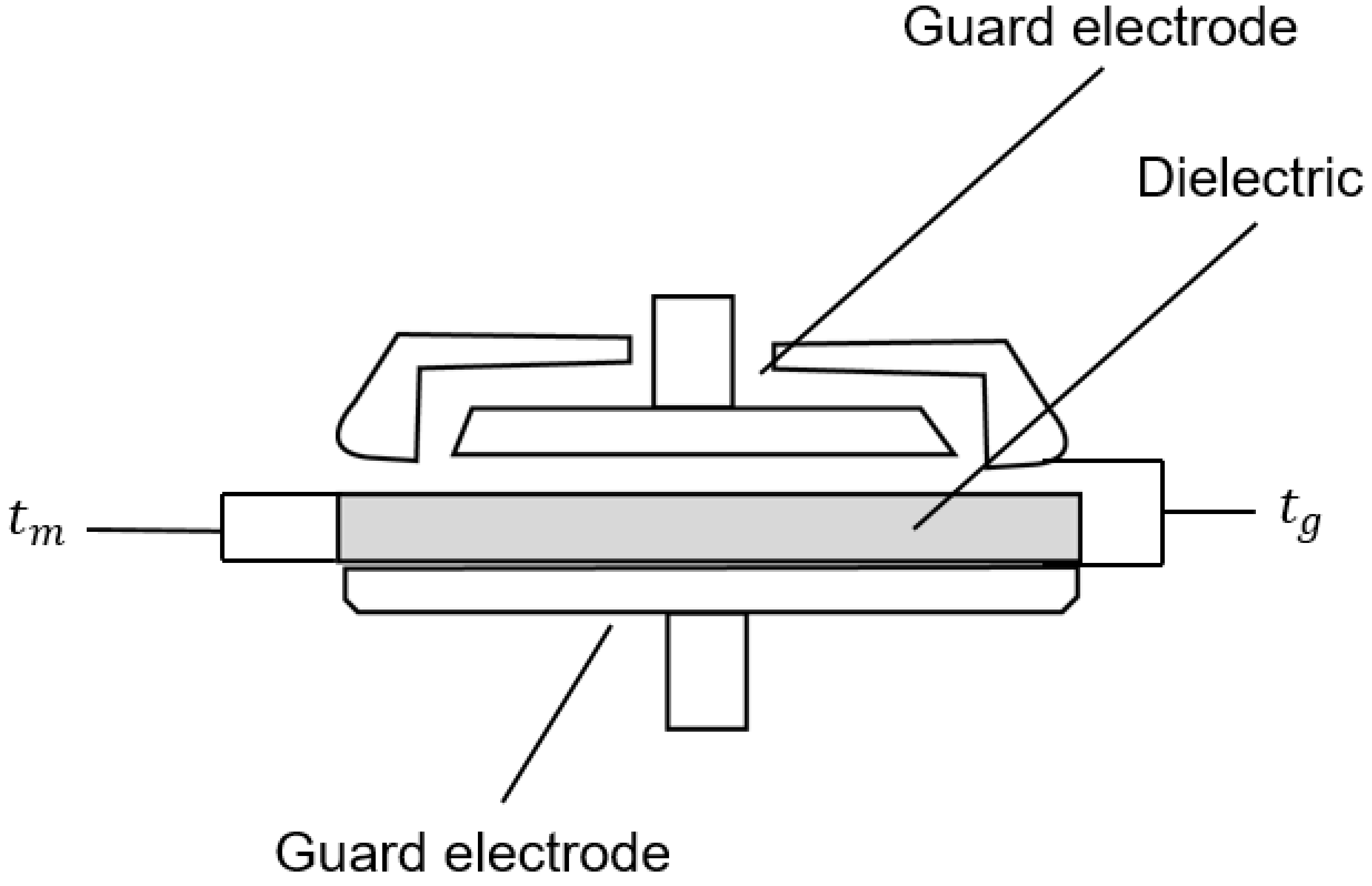
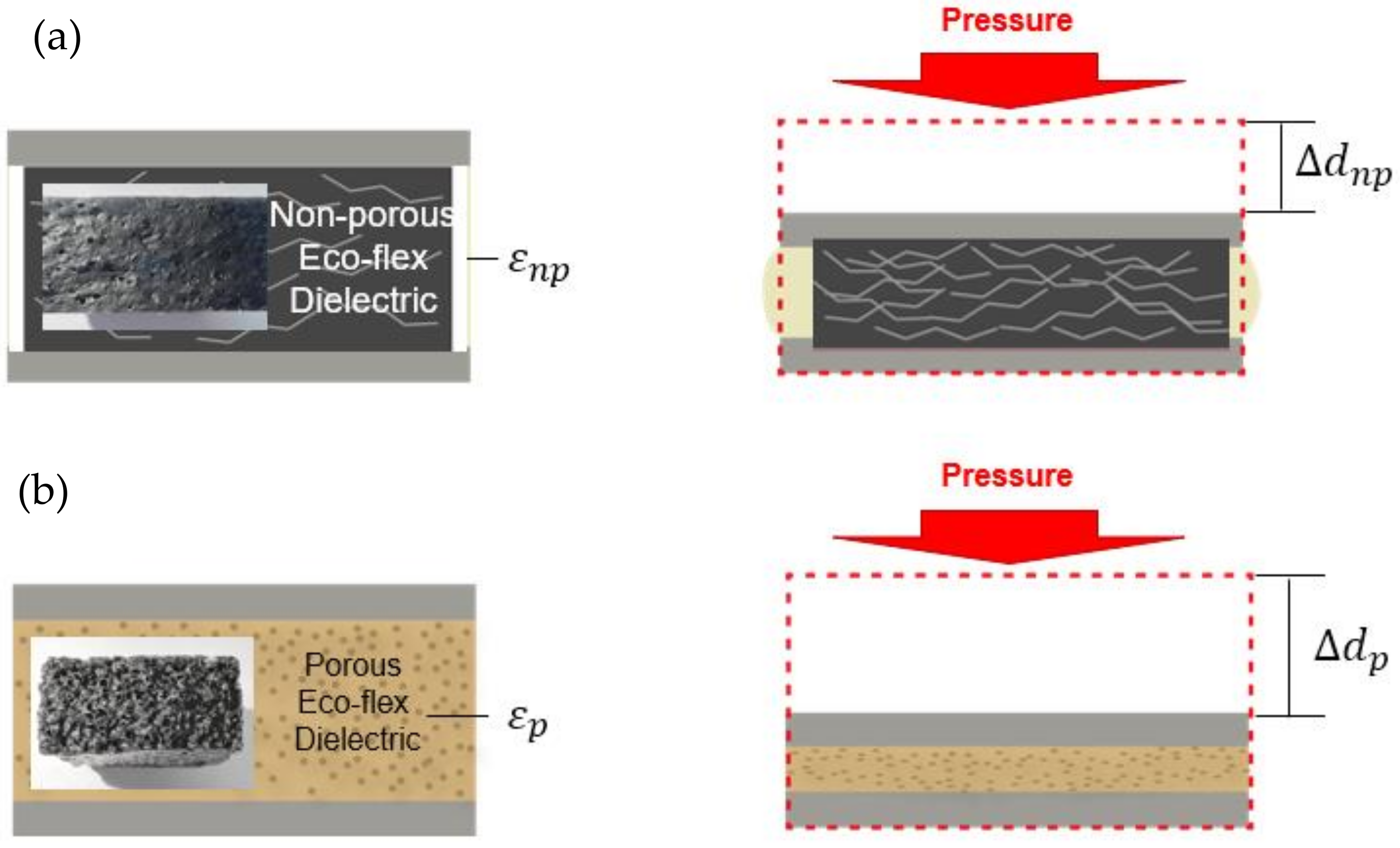
2.1. Conductive Tracks and Principle of the Transducer
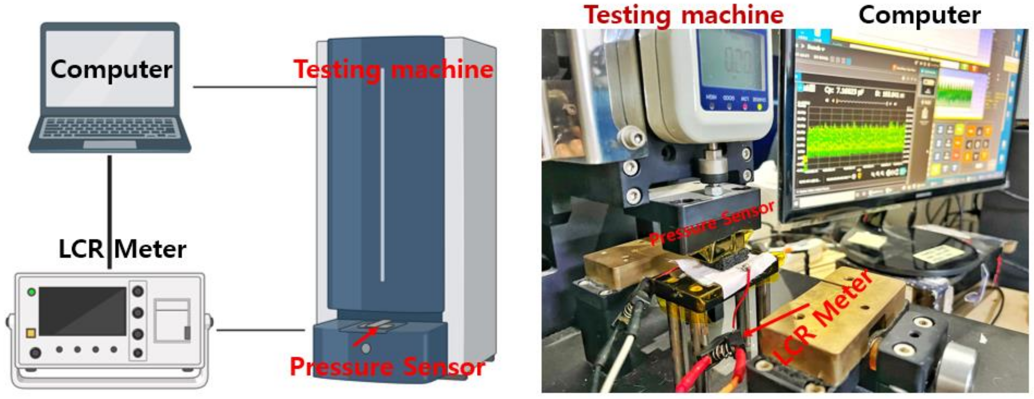
2.2. Methods
2.3. Materials
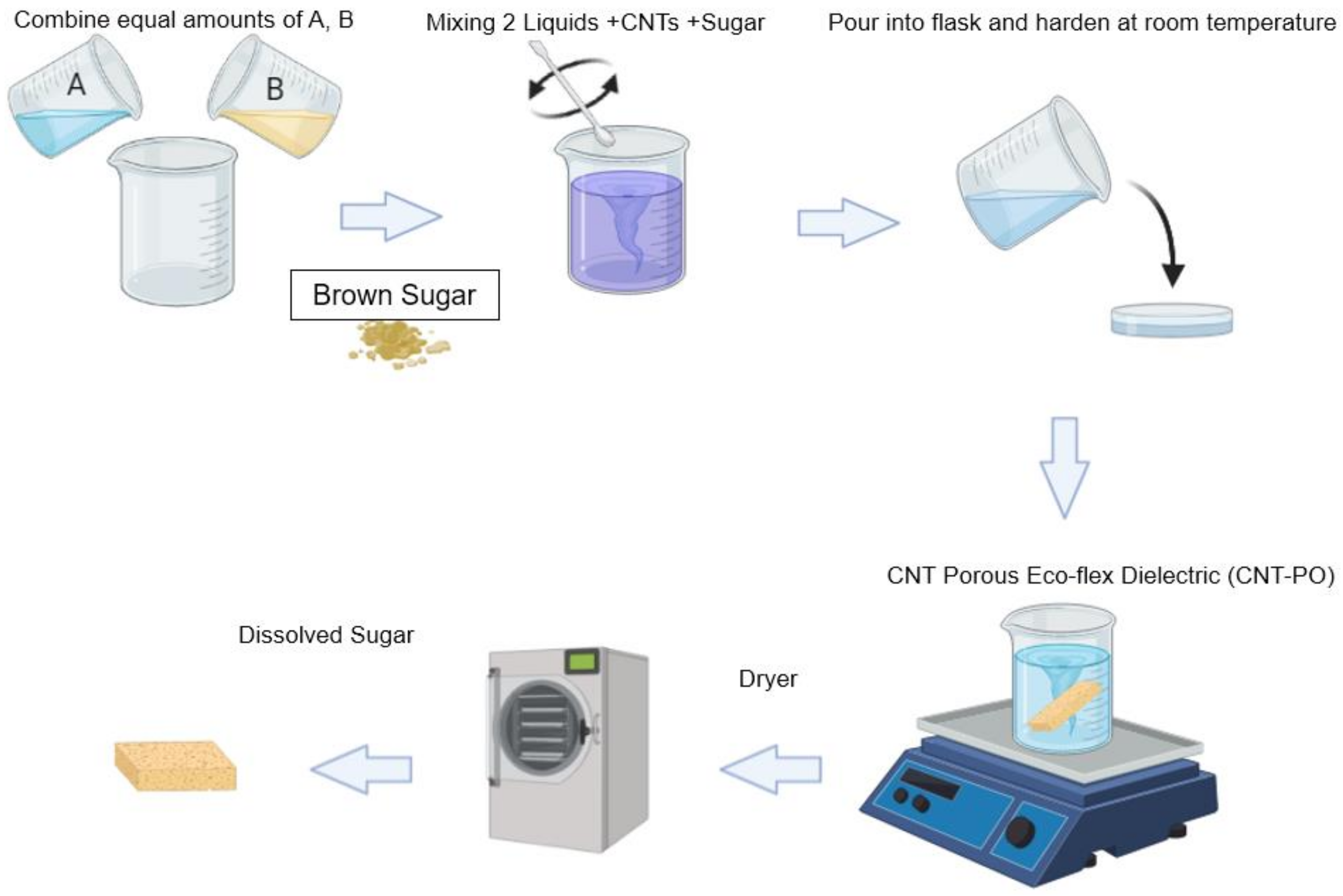
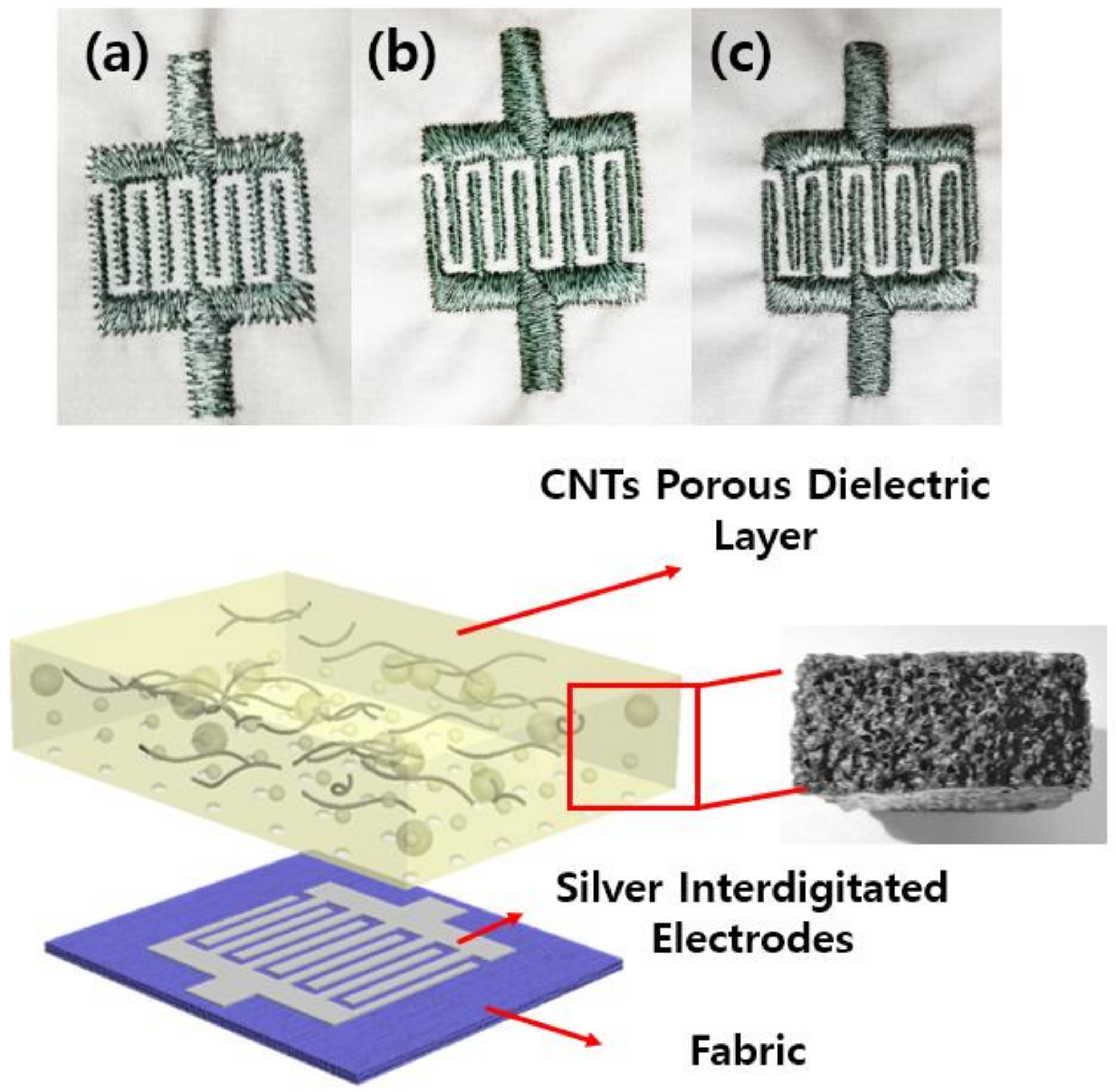
2.4. Fabrication
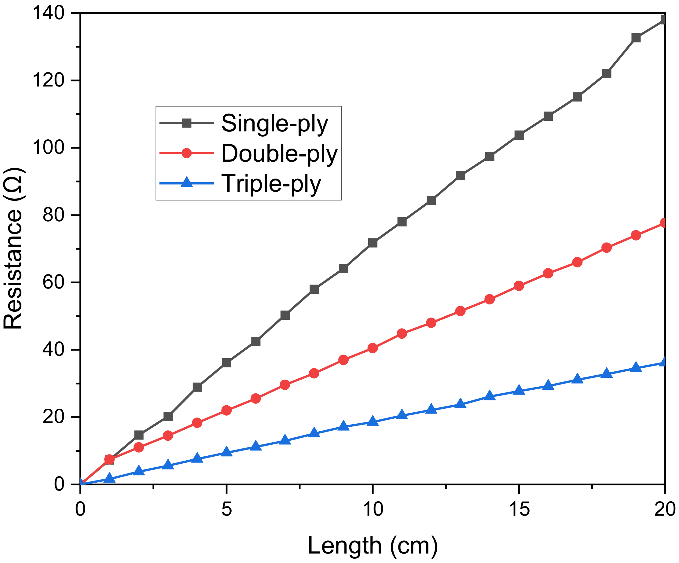
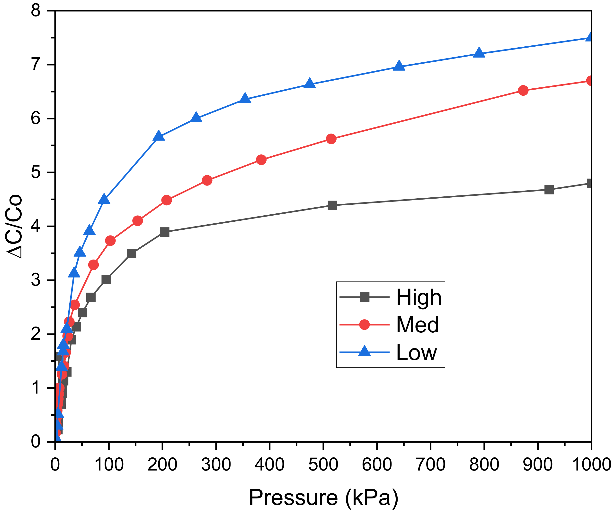
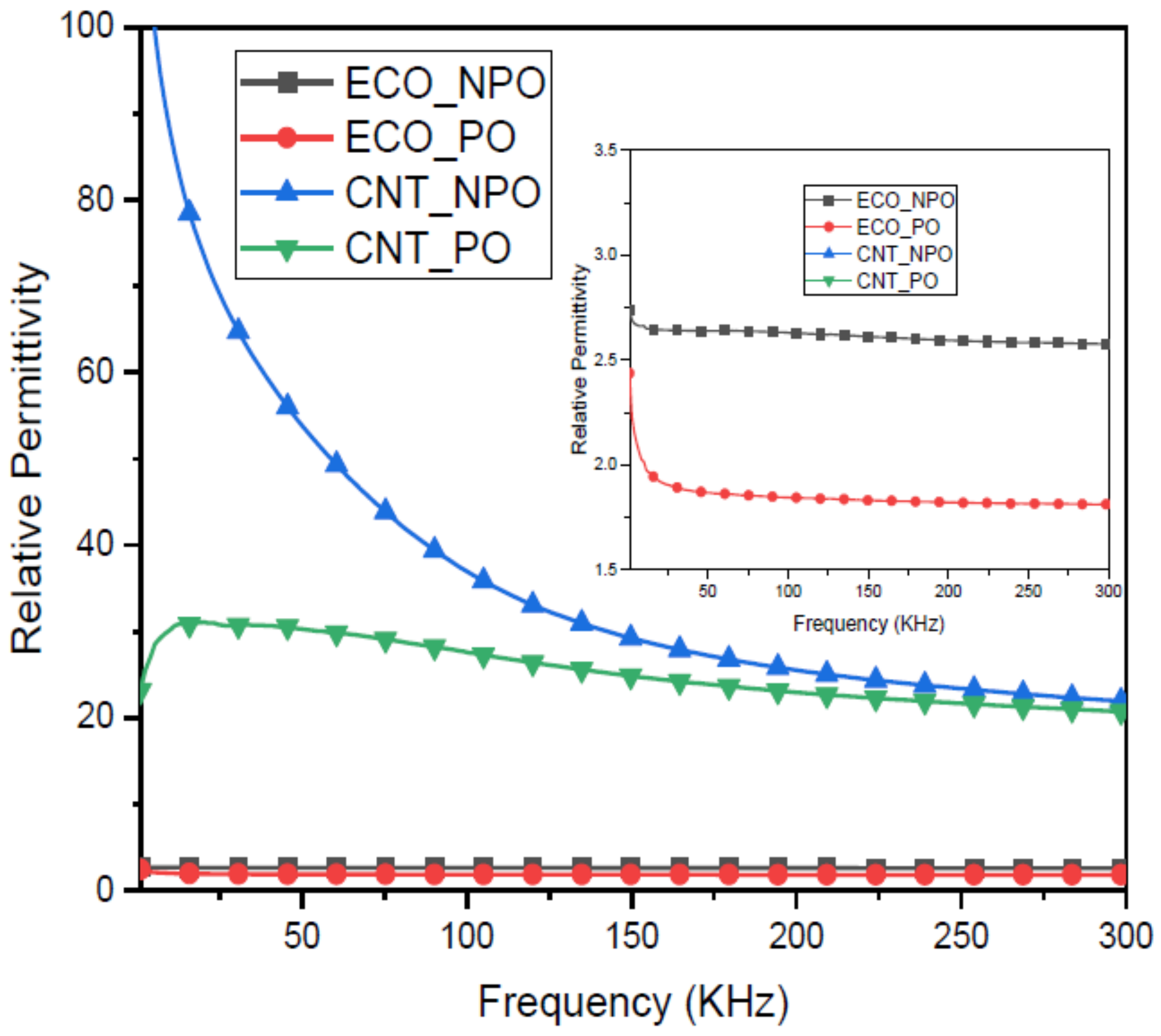
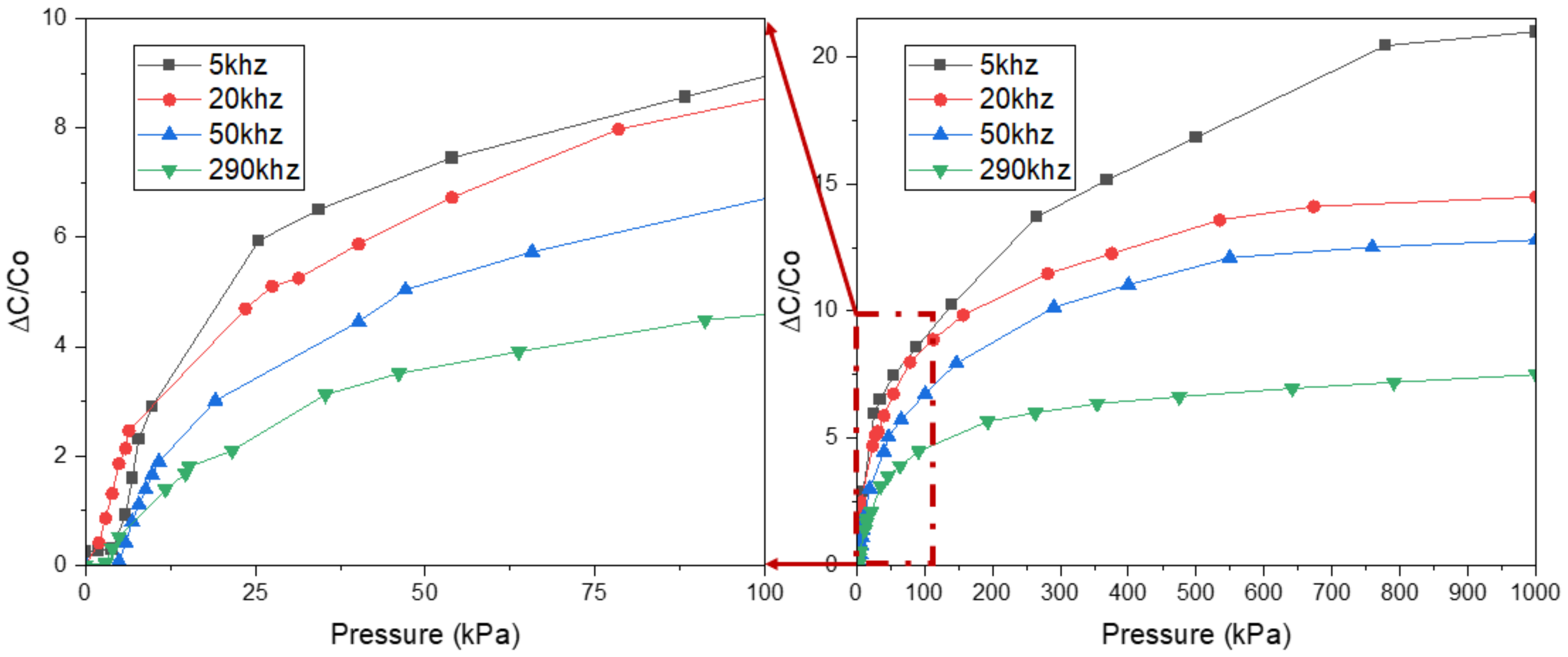
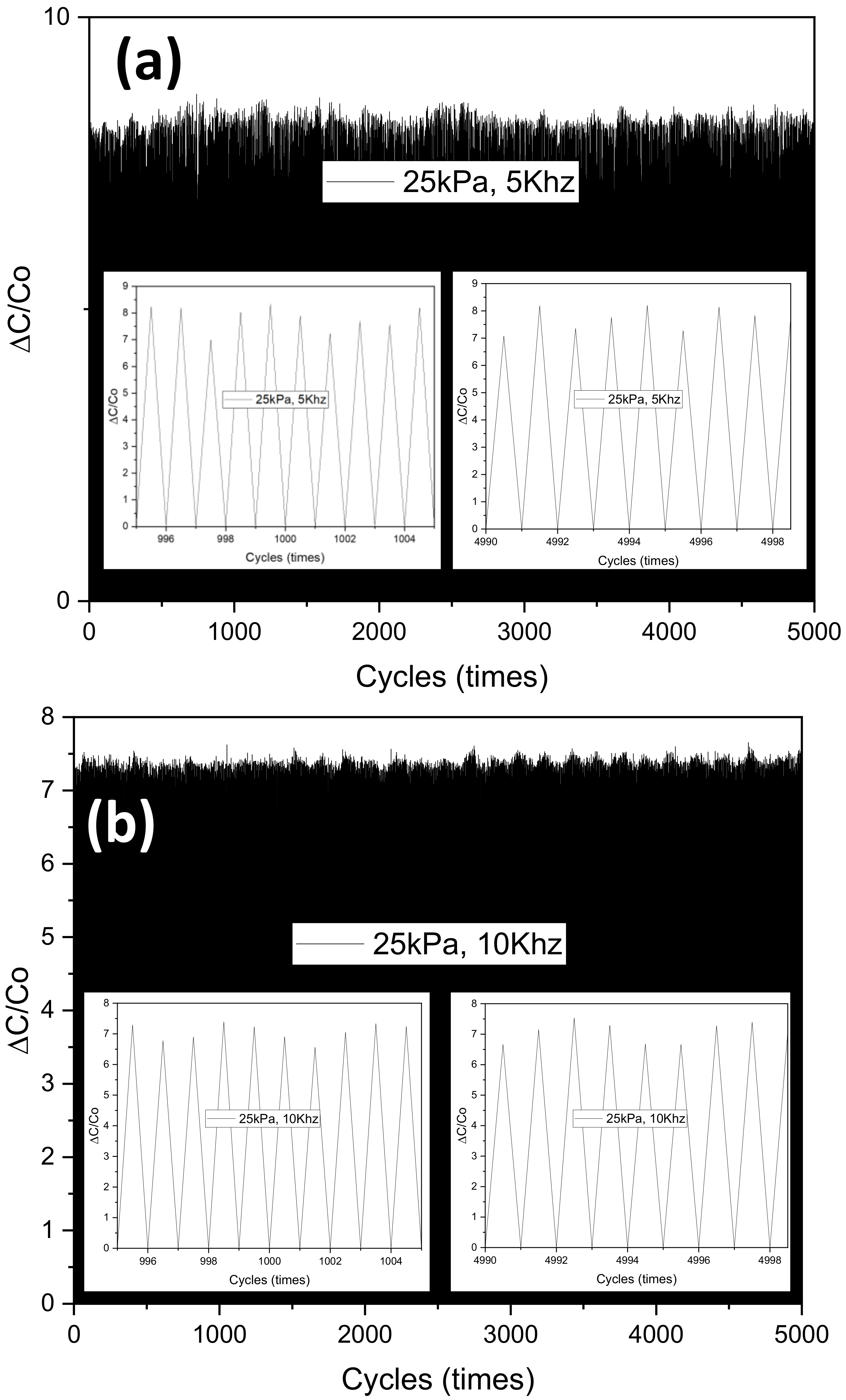
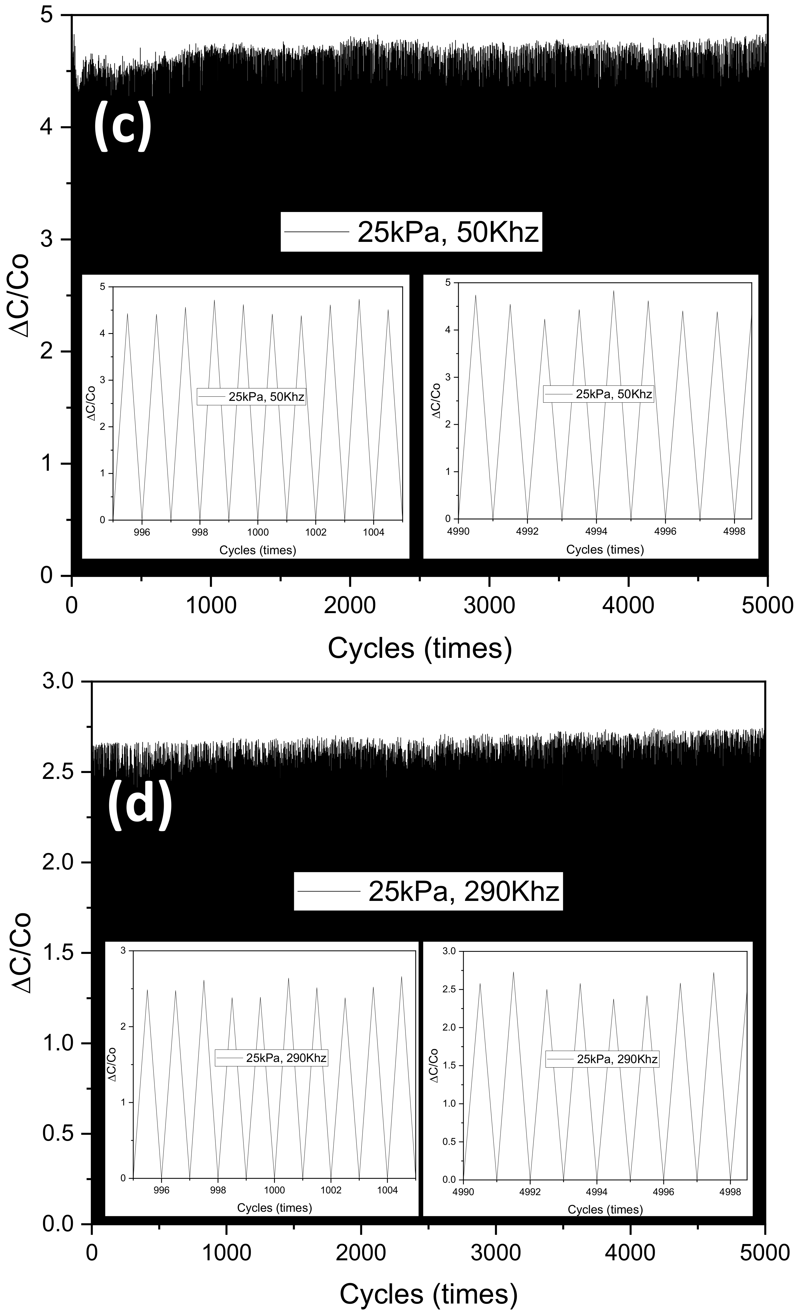
3. Results
4. Conclusions
Author Contributions
Funding
Institutional Review Board Statement
Informed Consent Statement
Data Availability Statement
Acknowledgments
Conflicts of Interest
References
- Hammock, M.L.; Chortos, A.; Tee, B.C.-K.; Tok, J.B.-H.; Bao, Z. 25th Anniversary Article: The Evolution of Electronic Skin (E-Skin): A Brief History, Design Considerations, and Recent Progress. Adv. Mater. 2013, 25, 5997–6038. [Google Scholar] [CrossRef] [PubMed]
- Heo, J.S.; Eom, J.; Kim, Y.-H.; Park, S.K. Recent Progress of Textile-Based Wearable Electronics: A Comprehensive Review of Materials, Devices, and Applications. Small 2018, 14, 1703034. [Google Scholar] [CrossRef] [PubMed]
- Wang, X.; Dong, L.; Zhang, H.; Yu, R.; Pan, C.; Wang, Z.L. Recent Progress in Electronic Skin. Adv. Sci. 2015, 2, 1500169. [Google Scholar] [CrossRef] [PubMed]
- Wan, S.; Bi, H.; Zhou, Y.; Xie, X.; Su, S.; Yin, K.; Sun, L. Graphene Oxide as High-Performance Dielectric Materials for Capacitive Pressure Sensors. Carbon 2017, 114, 209–216. [Google Scholar] [CrossRef]
- Guo, Y.; Gao, S.; Yue, W.; Zhang, C.; Li, Y. Anodized Aluminum Oxide-Assisted Low-Cost Flexible Capacitive Pressure Sensors Based on Double-Sided Nanopillars by a Facile Fabrication Method. ACS Appl. Mater. Interfaces 2019, 11, 48594–48603. [Google Scholar] [CrossRef]
- Thermochromic and Piezocapacitive Flexible Sensor Array by Combining Composite Elastomer Dielectrics and Transparent Ionic Hydrogel Electrodes—Charaya—2019—Advanced Materials Technologies—Wiley Online Library. Available online: https://onlinelibrary.wiley.com/doi/full/10.1002/admt.201900327 (accessed on 28 July 2022).
- Ruth, S.R.A.; Beker, L.; Tran, H.; Feig, V.R.; Matsuhisa, N.; Bao, Z. Rational Design of Capacitive Pressure Sensors Based on Pyramidal Microstructures for Specialized Monitoring of Biosignals. Adv. Funct. Mater. 2020, 30, 1903100. [Google Scholar] [CrossRef]
- Mahata, C.; Algadi, H.; Lee, J.; Kim, S.; Lee, T. Biomimetic-Inspired Micro-Nano Hierarchical Structures for Capacitive Pressure Sensor Applications. Measurement 2020, 151, 107095. [Google Scholar] [CrossRef]
- Fassler, A.; Majidi, C. Soft-Matter Capacitors and Inductors for Hyperelastic Strain Sensing and Stretchable Electronics. Smart Mater. Struct. 2013, 22, 055023. [Google Scholar] [CrossRef]
- Ke, K.; McMaster, M.; Christopherson, W.; Singer, K.D.; Manas-Zloczower, I. Highly Sensitive Capacitive Pressure Sensors Based on Elastomer Composites with Carbon Filler Hybrids. Compos. Part A Appl. Sci. Manuf. 2019, 126, 105614. [Google Scholar] [CrossRef]
- Guo, Z.; Mo, L.; Ding, Y.; Zhang, Q.; Meng, X.; Wu, Z.; Chen, Y.; Cao, M.; Wang, W.; Li, L. Printed and Flexible Capacitive Pressure Sensor with Carbon Nanotubes Based Composite Dielectric Layer. Micromachines 2019, 10, 715. [Google Scholar] [CrossRef] [PubMed]
- Metzger, C.; Fleisch, E.; Meyer, J.; Dansachmüller, M.; Graz, I.; Kaltenbrunner, M.; Keplinger, C.; Schwödiauer, R.; Bauer, S. Flexible-Foam-Based Capacitive Sensor Arrays for Object Detection at Low Cost. Appl. Phys. Lett. 2008, 92, 013506. [Google Scholar] [CrossRef]
- Kou, H.; Zhang, L.; Tan, Q.; Liu, G.; Dong, H.; Zhang, W.; Xiong, J. Wireless Wide-Range Pressure Sensor Based on Graphene/PDMS Sponge for Tactile Monitoring. Sci Rep 2019, 9, 3916. [Google Scholar] [CrossRef] [PubMed]
- Yang, C.; Li, L.; Zhao, J.; Wang, J.; Xie, J.; Cao, Y.; Xue, M.; Lu, C. Highly Sensitive Wearable Pressure Sensors Based on Three-Scale Nested Wrinkling Microstructures of Polypyrrole Films. ACS Appl. Mater. Interfaces 2018, 10, 25811–25818. [Google Scholar] [CrossRef] [PubMed]
- Li, J.; Fang, L.; Sun, B.; Li, X.; Kang, S.H. Review—Recent Progress in Flexible and Stretchable Piezoresistive Sensors and Their Applications. J. Electrochem. Soc. 2020, 167, 037561. [Google Scholar] [CrossRef]
- Park, S.-J.; Kim, J.; Chu, M.; Khine, M. Highly Flexible Wrinkled Carbon Nanotube Thin Film Strain Sensor to Monitor Human Movement. Adv. Mater. Technol. 2016, 1, 1600053. [Google Scholar] [CrossRef]
- Mu, J.; Hou, C.; Wang, G.; Wang, X.; Zhang, Q.; Li, Y.; Wang, H.; Zhu, M. An Elastic Transparent Conductor Based on Hierarchically Wrinkled Reduced Graphene Oxide for Artificial Muscles and Sensors. Adv. Mater. 2016, 28, 9491–9497. [Google Scholar] [CrossRef]
- Aparicio, R.; Hajimiri, A. Capacity Limits and Matching Properties of Integrated Capacitors. IEEE J. Solid-State Circuits 2002, 37, 384–393. [Google Scholar] [CrossRef]
- Ong, K.G.; Grimes, C.A. A Resonant Printed-Circuit Sensor for Remote Query Monitoring of Environmental Parameters. Smart Mater. Struct. 2000, 9, 421–428. [Google Scholar] [CrossRef]
- Truong, T.; Kim, J.-S.; Kim, J. Design and Optimization of Embroidered Antennas on Textile Using Silver Conductive Thread for Wearable Applications. Fibers Polym. 2021, 22, 2900–2909. [Google Scholar] [CrossRef]
- Bauhofer, W.; Kovacs, J.Z. A Review and Analysis of Electrical Percolation in Carbon Nanotube Polymer Composites. Compos. Sci. Technol. 2009, 69, 1486–1498. [Google Scholar] [CrossRef]
- Kwon, D.; Lee, T.-I.; Shim, J.; Ryu, S.; Kim, M.S.; Kim, S.; Kim, T.-S.; Park, I. Highly Sensitive, Flexible, and Wearable Pressure Sensor Based on a Giant Piezocapacitive Effect of Three-Dimensional Microporous Elastomeric Dielectric Layer. ACS Appl Mater Interfaces 2016, 8, 16922–16931. [Google Scholar] [CrossRef] [PubMed]
- Yoon, J.I.; Choi, K.S.; Chang, S.P. A Novel Means of Fabricating Microporous Structures for the Dielectric Layers of Capacitive Pressure Sensor. Microelectron. Eng. 2017, 179, 60–66. [Google Scholar] [CrossRef]
- Ko, Y.; Vu, C.C.; Kim, J. Carbonized Cotton Fabric-Based Flexible Capacitive Pressure Sensor Using a Porous Dielectric Layer with Tilted Air Gaps. Sensors 2021, 21, 3895. [Google Scholar] [CrossRef] [PubMed]
- Eom, S.; Lim, S. Stretchable Complementary Split Ring Resonator (CSRR)-Based Radio Frequency (RF) Sensor for Strain Direction and Level Detection. Sensors 2016, 16, 1667. [Google Scholar] [CrossRef]
- Hwang, J.; Kim, Y.; Yang, H.; Oh, J.H. Fabrication of Hierarchically Porous Structured PDMS Composites and Their Application as a Flexible Capacitive Pressure Sensor. Compos. Part B Eng. 2021, 211, 108607. [Google Scholar] [CrossRef]
- Shang, S.; Tang, C.; Jiang, B.; Song, J.; Jiang, B.; Zhao, K.; Liu, Y.; Wang, X. Enhancement of Dielectric Permittivity in Carbon Nanotube/Polyvinylidene Fluoride Composites by Constructing of Segregated Structure. Compos. Commun. 2021, 25, 100745. [Google Scholar] [CrossRef]
- Wang, J.; Jiu, J.; Nogi, M.; Sugahara, T.; Nagao, S.; Koga, H.; He, P.; Suganuma, K. A Highly Sensitive and Flexible Pressure Sensor with Electrodes and Elastomeric Interlayer Containing Silver Nanowires. Nanoscale 2015, 7, 2926–2932. [Google Scholar] [CrossRef]
- Lei, Z.; Wang, Q.; Sun, S.; Zhu, W.; Wu, P. A Bioinspired Mineral Hydrogel as a Self-Healable, Mechanically Adaptable Ionic Skin for Highly Sensitive Pressure Sensing. Adv. Mater. 2017, 29, 1700321. [Google Scholar] [CrossRef]
- Atalay, O.; Atalay, A.; Gafford, J.; Walsh, C. A Highly Sensitive Capacitive-Based Soft Pressure Sensor Based on a Conductive Fabric and a Microporous Dielectric Layer. Adv. Mater. Technol. 2018, 3, 1700237. [Google Scholar] [CrossRef]
- Kou, H.; Zhang, L.; Tan, Q.; Liu, G.; Lv, W.; Lu, F.; Dong, H.; Xiong, J. Wireless Flexible Pressure Sensor Based on Micro-Patterned Graphene/PDMS Composite. Sens. Actuators A Phys. 2018, 277, 150–156. [Google Scholar] [CrossRef]
- Feng, C.; Yi, Z.; Jin, X.; Seraji, S.M.; Dong, Y.; Kong, L.; Salim, N. Solvent Crystallization-Induced Porous Polyurethane/Graphene Composite Foams for Pressure Sensing. Compos. Part B Eng. 2020, 194, 108065. [Google Scholar] [CrossRef]
- Chen, S.; Song, Y.; Xu, F. Flexible and Highly Sensitive Resistive Pressure Sensor Based on Carbonized Crepe Paper with Corrugated Structure. ACS Appl. Mater. Interfaces 2018, 10, 34646–34654. [Google Scholar] [CrossRef] [PubMed]


| Parameter | Dimension |
|---|---|
| Finger width | 1 (mm) |
| Gap between fingers | 1 (mm) |
| Length of the overlapped region | 1.2 (mm) |
| Width of feedline | 3.5 (mm) |
| Samples | Volume of Ecoflex (g) | Volume of CNTs (g) | Volume of sugar in the mixture (g) | Percentage of sugar in the Ecoflex (%) | Percentage of CNTs in the Ecoflex (%) |
|---|---|---|---|---|---|
| CNTs + Ecoflex | 1 | 0 | 0 | 0.25 | |
| CNTs + Ecoflex + Sugar | 1 | 1 | 100 | 0.25 | |
| Ecoflex + Sugar | 1 | 0 | 1 | 100 | 0 |
Publisher’s Note: MDPI stays neutral with regard to jurisdictional claims in published maps and institutional affiliations. |
© 2022 by the authors. Licensee MDPI, Basel, Switzerland. This article is an open access article distributed under the terms and conditions of the Creative Commons Attribution (CC BY) license (https://creativecommons.org/licenses/by/4.0/).
Share and Cite
Truong, T.; Kim, J.-S.; Kim, J. Development of Embroidery-Type Pressure Sensor Dependent on Interdigitated Capacitive Method. Polymers 2022, 14, 3446. https://doi.org/10.3390/polym14173446
Truong T, Kim J-S, Kim J. Development of Embroidery-Type Pressure Sensor Dependent on Interdigitated Capacitive Method. Polymers. 2022; 14(17):3446. https://doi.org/10.3390/polym14173446
Chicago/Turabian StyleTruong, TranThuyNga, Ji-Seon Kim, and Jooyong Kim. 2022. "Development of Embroidery-Type Pressure Sensor Dependent on Interdigitated Capacitive Method" Polymers 14, no. 17: 3446. https://doi.org/10.3390/polym14173446
APA StyleTruong, T., Kim, J.-S., & Kim, J. (2022). Development of Embroidery-Type Pressure Sensor Dependent on Interdigitated Capacitive Method. Polymers, 14(17), 3446. https://doi.org/10.3390/polym14173446