

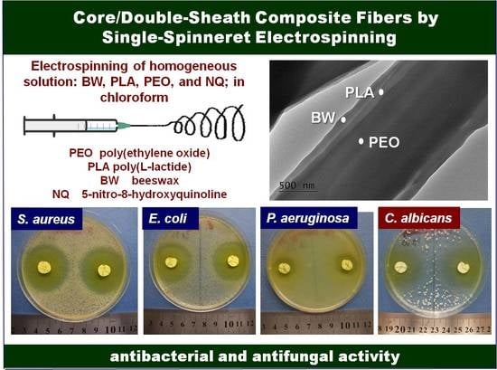
Core/Double-Sheath Composite Fibers from Poly(ethylene oxide), Poly(L-lactide) and Beeswax by Single-Spinneret Electrospinning
 , , , and
Abstract
:
1. Introduction
2. Materials and Methods
2.1. Materials
2.2. Preparation and Characterization of Electrospun Composite Fibrous Materials from PEO/PLA/BW
2.3. Preparation and Characterization of Electrospun Fibrous Materials from PEO/PLA/BW/NQ
2.4. Assessment of the Behavior of Electrospun Composite Materials from PEO/PLA/BW and PEO/PLA/BW/NQ in Contact with Pathogenic Microorganisms
2.5. Statistical Analysis
3. Results and Discussion
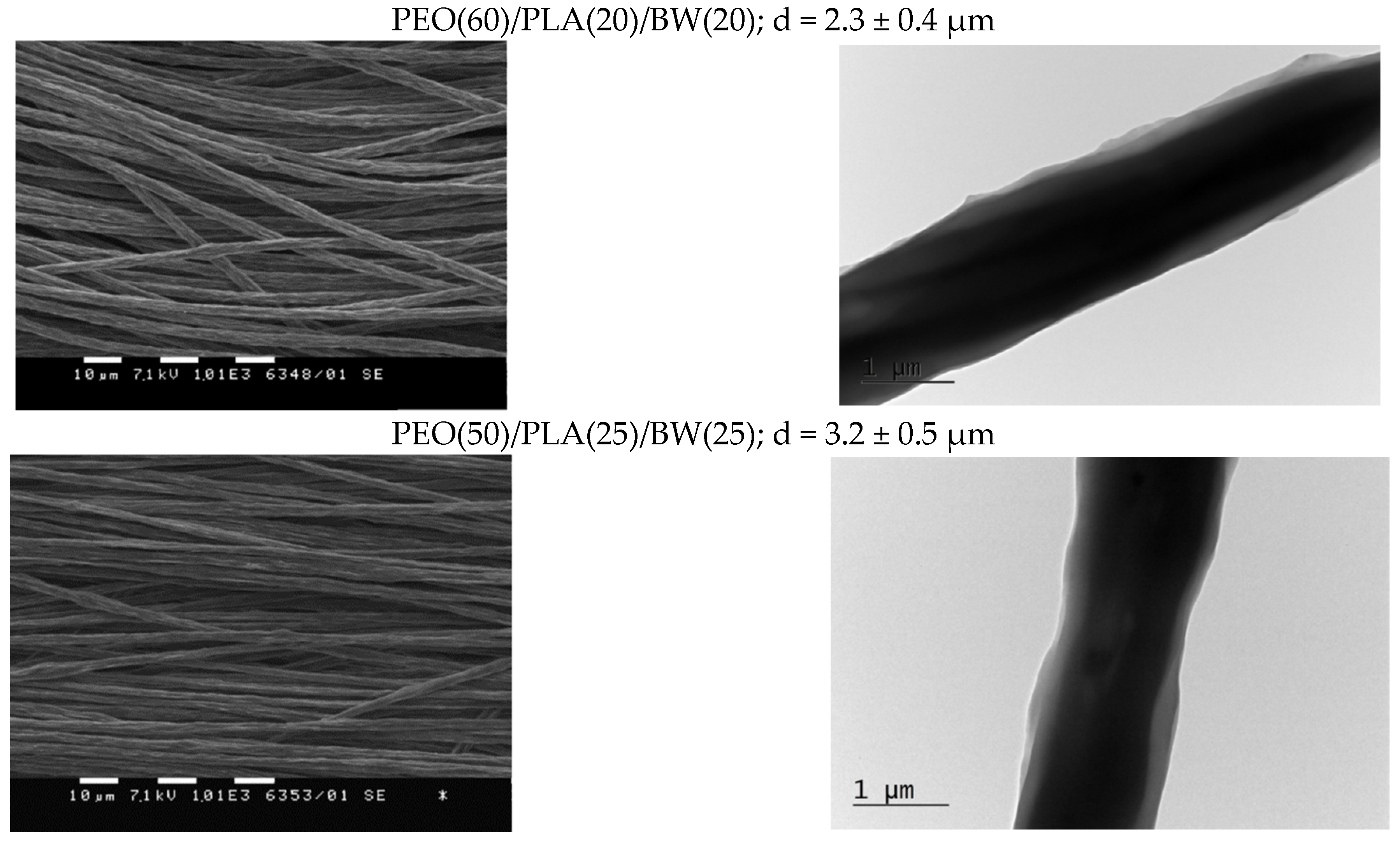
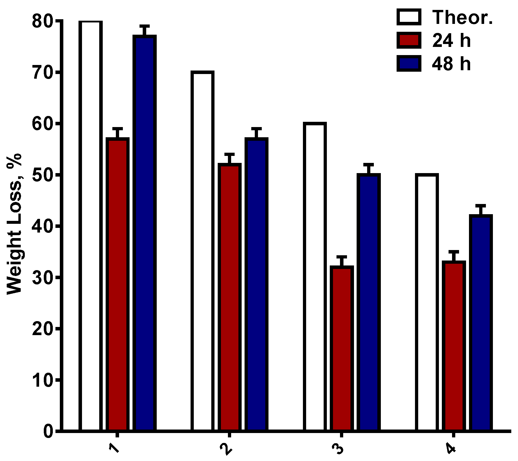
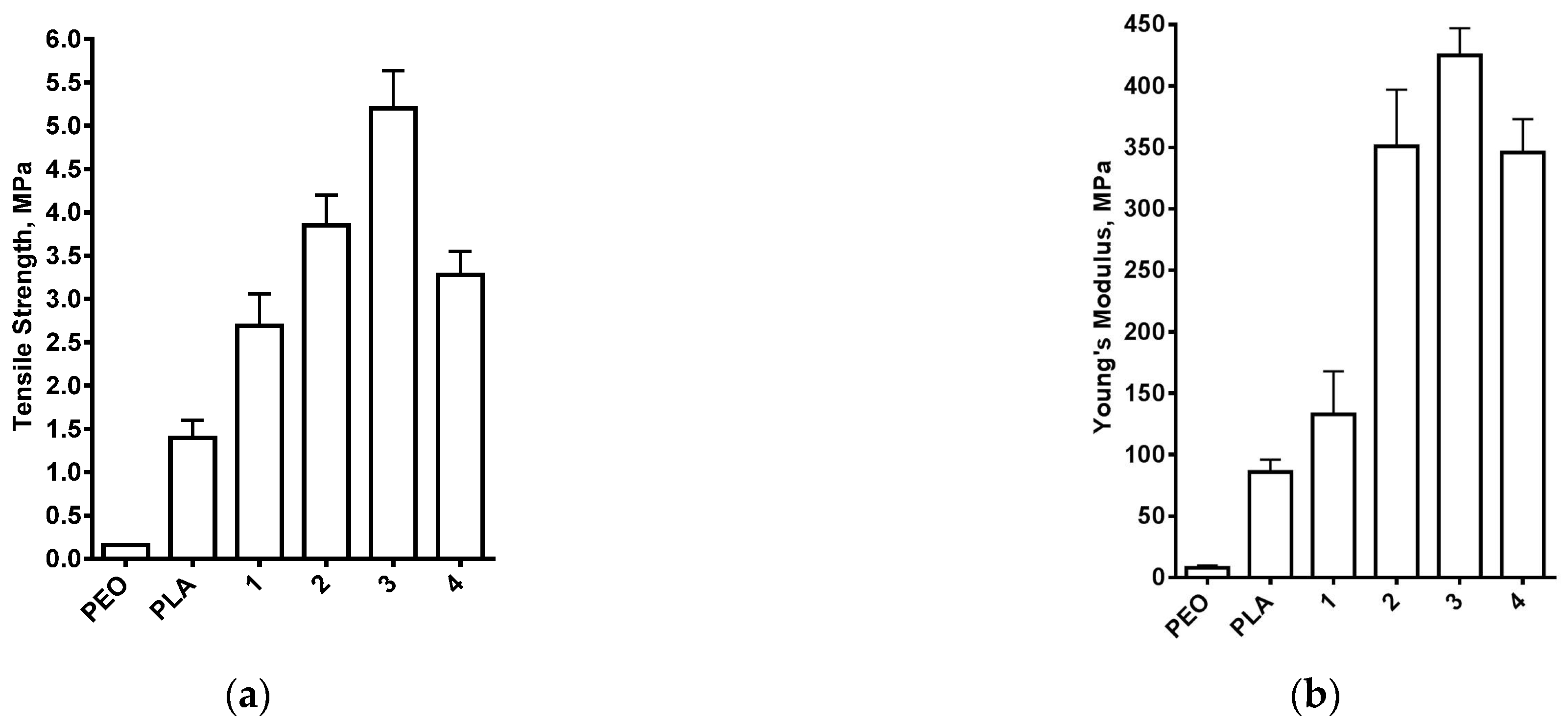
3.1. Composite PEO/PLA/BW Fibrous Materials Prepared by Electrospinning at Different Weight Ratios between the Partners
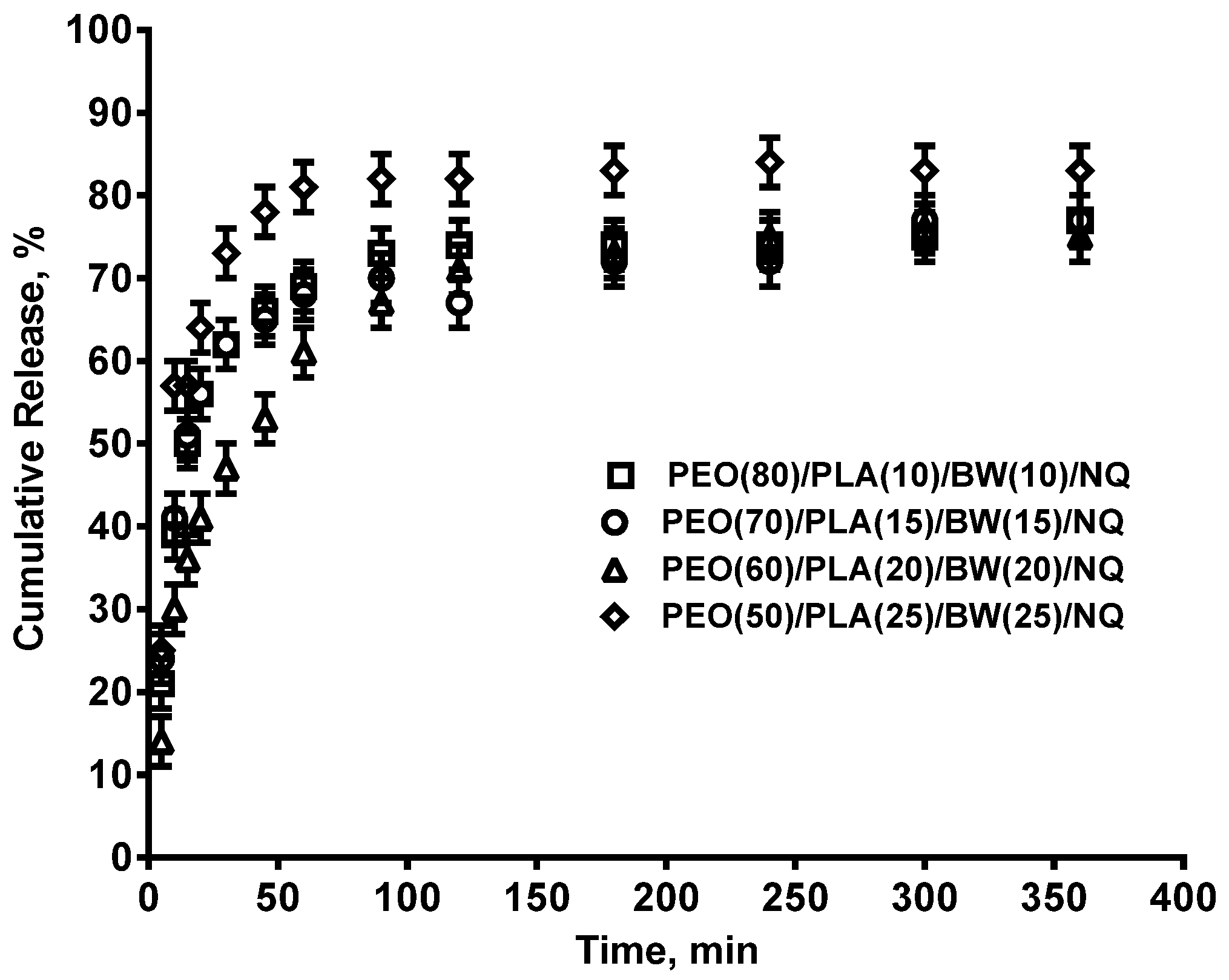
3.2. Composite PEO/PLA/BW/NQ Fibrous Materials Prepared by Electrospinning
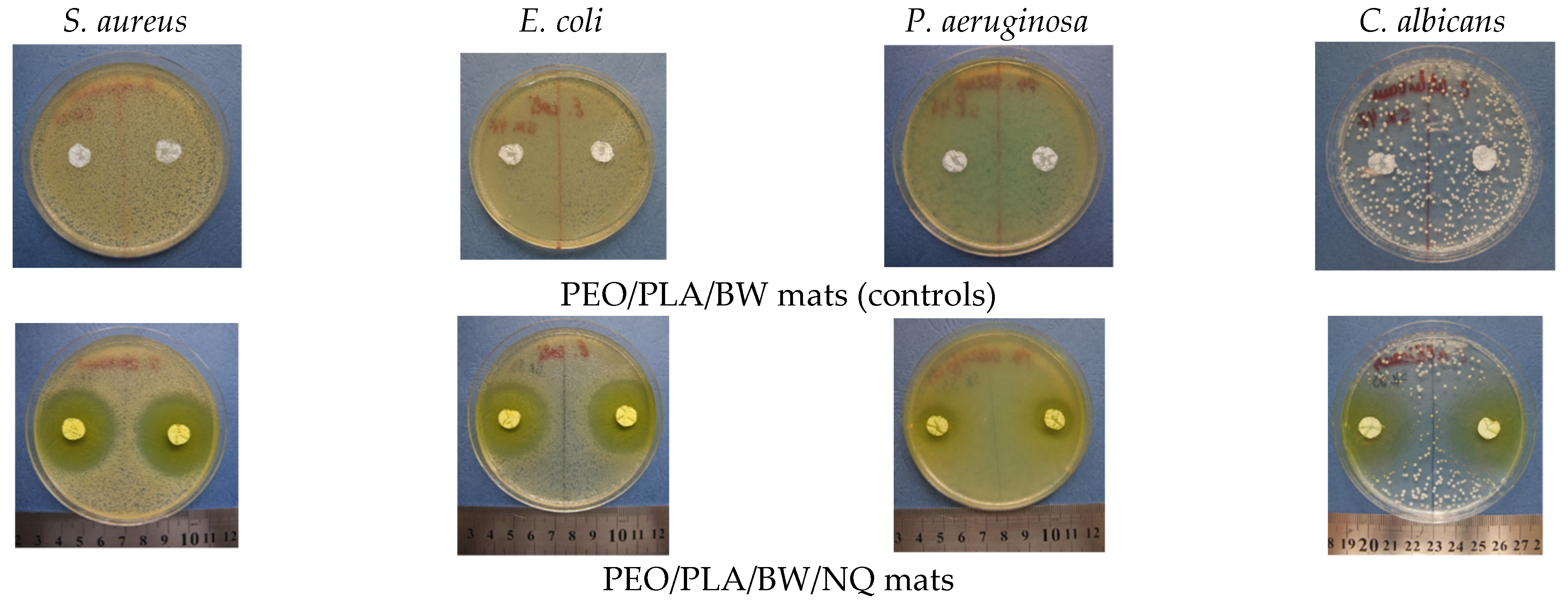
3.3. Evaluation of the Effect of Electrospun Composite Materials from PEO/PLA/BW and PEO/PLA/BW/NQ on Contact with Pathogenic Microorganisms
4. Conclusions
Supplementary Materials
Author Contributions
Funding
Institutional Review Board Statement
Data Availability Statement
Acknowledgments
Conflicts of Interest
References
- McCann, J.T.; Li, D.; Xia, Y. Electrospinning of nanofibers with core-sheath, hollow, or porous structures. J. Mater. Chem. 2005, 15, 735–738. [Google Scholar] [CrossRef]
- Paneva, D.; Ignatova, M.; Manolova, N.; Rashkov, I. Novel chitosan-containing micro- and nanofibrous materials by electrospinning: Preparation and biomedical application. In Nanofibers: Fabrication, Performance, and Applications; Chang, W.N., Ed.; Science Publishers, Inc.: New York, NY, USA, 2009; Chapter 3; pp. 73–151. [Google Scholar]
- Yang, X.; Wang, J.; Guo, H.; Liu, L.; Xu, W.; Duan, G. Structural design toward functional materials by electrospinning: A review. e-Polymers 2020, 20, 682–712. [Google Scholar] [CrossRef]
- Jiffrin, R.; Razak, S.I.A.; Jamaludin, M.I.; Hamzah, A.S.A.; Mazian, M.A.; Jaya, M.A.T.; Nasrullah, M.Z.; Majrashi, M.; Theyab, A.; Aldarmahi, A.A.; et al. Electrospun nanofiber composites for drug delivery: A review on current progresses. Polymers 2022, 14, 3725. [Google Scholar] [CrossRef]
- Abdullah, M.F.; Nuge, T.; Andriyana, A.; Ang, B.C.; Muhamad, F. Core-shell fibers: Design, roles, and controllable release strategies in tissue engineering and drug delivery. Polymers 2019, 11, 2008. [Google Scholar] [CrossRef] [PubMed] [Green Version]
- Pant, B.; Park, M.; Park, S.-J. Drug delivery applications of core-sheath nanofibers prepared by coaxial electrospinning: A review. Pharmaceutics 2019, 11, 305. [Google Scholar] [CrossRef] [Green Version]
- Palit, S.; Kreplak, L.; Frampton, J.P. Formation of core-sheath polymer fibers by free surface spinning of aqueous two-phase systems. Langmuir 2022, 38, 4617–4624. [Google Scholar] [CrossRef]
- Elahi, M.F.; Lu, W.; Guoping, G.; Khan, F. Core-shell fibers for biomedical applications—A review. J. Bioeng. Biomed. Sci. 2013, 3, 1–14. [Google Scholar] [CrossRef] [Green Version]
- Korina, E.; Stoilova, O.; Manolova, N.; Rashkov, I. Polymer fibers with magnetic core decorated with titanium dioxide prospective for photocatalytic water treatment. J. Environ. Chem. Eng. 2018, 6, 2075–2084. [Google Scholar] [CrossRef]
- Rathore, P.; Schiffman, J.D. Beyond the single-nozzle: Coaxial electrospinning enables innovative nanofiber chemistries, geometries, and applications. ACS Appl. Mater. Interfaces 2021, 13, 48–66. [Google Scholar] [CrossRef]
- Ouerghemmi, S.; Degoutin, S.; Maton, M.; Tabary, N.; Cazaux, F.; Neut, C.; Blanchemain, N.; Martel, B. Core-sheath electrospun nanofibers based on chitosan and cyclodextrin polymer for the prolonged release of triclosan. Polymers 2022, 14, 1955. [Google Scholar] [CrossRef]
- Bazilevsky, A.V.; Yarin, A.L.; Megaridis, C.M. Co-electrospinning of core-shell fibers using a single-nozzle technique. Langmuir 2007, 23, 2311–2314. [Google Scholar] [CrossRef] [PubMed]
- Moydeen, M.A.; Padusha, S.A.M.; Thamer, B.M.; Ahamed, A.N.; Al-Enizi, A.M.; El-Hamshary, H.; El-Newehy, M.H. Single-nozzle core-shell electrospun nanofibers of PVP/dextran as drug delivery system. Fibers Polym. 2019, 20, 2078–2089. [Google Scholar] [CrossRef]
- Niu, Q.; Zeng, L.; Mu, X.; Nie, J.; Ma, G. Preparation and characterization of core-shell nanofibers by electrospinning combined with in situ UV photopolymerization. J. Ind. Eng. Chem. 2016, 34, 337–343. [Google Scholar] [CrossRef]
- Niu, Q.; Mu, X.; Nie, J.; Ma, G. Potential fabrication of core-shell electrospun nanofibers from a two-step method: Electrospinning and photopolymerization. J. Ind. Eng. Chem. 2016, 38, 193–199. [Google Scholar] [CrossRef]
- Wei, M.; Lee, J.; Kang, B.; Mead, J. Preparation of core-sheath nanofibers from conducting polymer blends. Macromol. Rapid Commun. 2005, 26, 1127–1132. [Google Scholar] [CrossRef]
- Wei, M.; Kang, B.; Sung, C.; Mead, J. Core-Sheath structure in electrospun nanofibers from polymer blends. Macromol. Mater. Eng. 2006, 291, 1307–1314. [Google Scholar] [CrossRef]
- Zhang, J.-F.; Yang, D.-Z.; Xu, F.; Zhang, Z.-P.; Yin, R.-X.; Nie, J. Electrospun core-shell structure nanofibers from homogeneous solution of poly(ethylene oxide)/chitosan. Macromolecules 2009, 42, 5278–5284. [Google Scholar] [CrossRef]
- Won, J.J.; Nirmala, R.; Navamathavan, R.; Kim, H.Y. Electrospun core-shell nanofibers from homogeneous solution of poly(vinyl alcohol)/bovine serum albumin. Int. J. Biol. Macromol. 2012, 50, 1292–1298. [Google Scholar] [CrossRef]
- Mu, X.; Liu, Y.; Fang, D.; Wang, Z.; Nie, J.; Ma, G. Electric field induced phase separation on electrospinning polyelectrolyte based core-shell nanofibers. Carbohydr. Polym. 2012, 90, 1582–1586. [Google Scholar] [CrossRef]
- Xu, T.; Yang, H.; Yang, D.; Yu, Z.-Z. Polylactic acid nanofiber scaffold decorated with chitosan island-like topography for bone tissue engineering. ACS Appl. Mater. Interfaces 2017, 9, 21094–21104. [Google Scholar] [CrossRef]
- Wang, M.; Fang, D.; Wang, N.; Jiang, S.; Nie, J.; Yu, Q.; Ma, G. Preparation of PVDF/PVP core-shell nanofibers mats via homogeneous electrospinning. Polymer 2014, 55, 2188–2196. [Google Scholar] [CrossRef]
- Huang, W.; Wang, M.-J.; Liu, C.-L.; You, J.; Chen, S.-C.; Wang, Y.-Z.; Liu, Y. Phase separation in electrospun nanofibers controlled by crystallization induced self-assembly. J. Mater. Chem. A 2014, 2, 8416–8424. [Google Scholar] [CrossRef]
- Liu, D.; Shi, Q.; Jin, S.; Shao, Y.; Huang, J. Self-assembled core-shell structured organic nanofibers fabricated by single-nozzle electrospinning for highly sensitive ammonia sensors. InfoMat 2019, 1, 525–532. [Google Scholar] [CrossRef] [Green Version]
- Ma, L.; Deng, L.; Chen, J. Applications of poly(ethylene oxide) in controlled release tablet systems: A review. Drug Dev. Ind. Pharm. 2014, 40, 845–851. [Google Scholar] [CrossRef]
- Deitzel, J.M.; Kleinmeyer, J.D.; Hirvonen, J.K.; Beck Tan, N.C. Controlled deposition of electrospun poly(ethylene oxide) fibers. Polymer 2001, 42, 8163–8170. [Google Scholar] [CrossRef]
- Spasova, M.; Manolova, N.; Paneva, D.; Rashkov, I. Preparation of chitosan-containing nanofibres by electrospinning of chitosan/poly(ethylene oxide) blend solutions. e-Polymers 2004, 056, 1–12. [Google Scholar] [CrossRef]
- Filip, P.; Peer, P. Characterization of poly(ethylene oxide) nanofibers—Mutual relations between mean diameter of electrospun nanofibers and solution characteristics. Processes 2019, 7, 948. [Google Scholar] [CrossRef] [Green Version]
- Son, W.K.; Youk, J.H.; Lee, T.S.; Park, W.H. The effects of solution properties and polyelectrolyte on electrospinning of ultrafine poly(ethylene oxide) fibers. Polymer 2004, 45, 2959–2966. [Google Scholar] [CrossRef]
- Raquez, J.-M.; Habibi, Y.; Murariu, M.; Dubois, P. Polylactide (PLA)-based nanocomposites. Prog. Polym. Sci. 2013, 38, 1504–1542. [Google Scholar] [CrossRef]
- Beltrán, F.R.; Arrieta, M.P.; Moreno, E.; Gaspar, G.; Muneta, L.M.; Carrasco-Gallego, R.; Yáñez, S.; Hidalgo-Carvajal, D.; de la Orden, M.U.; Martínez Urreaga, J. Evaluation of the technical viability of distributed mechanical recycling of PLA 3D printing wastes. Polymers 2021, 13, 1247. [Google Scholar] [CrossRef]
- Capuana, E.; Lopresti, F.; Ceraulo, M.; La Carrubba, V. Poly-L-lactic acid (PLLA)-based biomaterials for regenerative medicine: A review on processing and applications. Polymers 2022, 14, 1153. [Google Scholar] [CrossRef] [PubMed]
- Ruguo, Z.; Hua, Z.; Hong, Z.; Ying, F.; Kun, L.; Wenwen, Z. Thermal analysis of four insect waxes based on differential scanning calorimetry (DSC). Procedia Eng. 2011, 18, 101–106. [Google Scholar] [CrossRef]
- Janesch, J.; Arminger, B.; Gindl-Altmutter, W.; Hansmann, C. Superhydrophobic coatings on wood made of plant oil and natural wax. Prog. Org. Coat. 2020, 148, 105891. [Google Scholar] [CrossRef]
- Bogdanov, S. Beeswax: Quality issues today. Bee World 2004, 85, 46–50. [Google Scholar] [CrossRef]
- Fratini, F.; Cilia, G.; Turchi, B.; Felicioli, A. Beeswax: A minireview of its antimicrobial activity and its application in medicine. Asian Pac. J. Trop. Dis. 2016, 9, 839–843. [Google Scholar] [CrossRef]
- Kyuchyuk, S.; Paneva, D.; Karashanova, D.; Markova, N.; Georgieva, A.; Toshkova, R.; Manolova, N.; Rashkov, I. Core-sheath-like poly(ethylene oxide)/beeswax composite fibers prepared by single-spinneret electrospinning. Antibacterial, antifungal, and antitumor activities. Macromol. Biosci. 2022, 22, 2200015. [Google Scholar] [CrossRef]
- Kurata, M.; Tsunashima, Y. Polymer Handbook, 4th ed.; Brandrup, J., Immergut, E.H., Grulke, E.A., Eds.; John Wiley & Sons, Inc.: Hoboken, NJ, USA, 1999. [Google Scholar]
- Spasova, M.; Mincheva, R.; Paneva, D.; Manolova, N.; Rashkov, I. Criteria for complex evaluation of the morphology and alignment of electrospun polymer nanofibers. J. Bioact. Compat. Polym. 2006, 21, 465–479. [Google Scholar] [CrossRef]
- Stoyanova, N.; Paneva, D.; Mincheva, R.; Toncheva, A.; Manolova, N.; Dubois, P.; Rashkov, I. Poly(L-lactide) and poly(butylene succinate) immiscible blends: From electrospinning to biologically active materials. Mater. Sci. Eng. C 2014, 41, 119–126. [Google Scholar] [CrossRef]
- Xu, X.; Jiang, L.; Zhou, Z.; Wu, X.; Wang, Y. Preparation and properties of electrospun soy protein isolate/polyethylene oxide nanofiber membranes. ACS Appl. Mater. Interfaces 2012, 4, 4331–4337. [Google Scholar] [CrossRef]
- Rosita, N.; Setyawan, D.; Soeratri, W.; Mrtodihardjo, S. Physical characterization of beeswax and glyceryl monostearat binary system to predict characteristics of solid lipid nanoparticle (SLN) loaded para methoxy cinnamic acid (PMCA). Int. J. Pharm. Pharm. Sci. 2014, 6, 939–945. [Google Scholar]
- Dinker, A.; Agarwal, M.; Agarwal, G.D. Experimental study on thermal performance of beeswax as thermal storage material. Mater. Today Proc. 2017, 4, 10529–10533. [Google Scholar] [CrossRef]
- Li, R.; Wu, Y.; Bai, Z.; Guo, J.; Chen, X. Effect of molecular weight of polyethylene glycol on crystallization behaviors, thermal properties and tensile performance of polylactic acid stereocomplexes. RSC Adv. 2020, 10, 42120–42127. [Google Scholar] [CrossRef]
- Eom, Y.; Choi, B.; Park, S.A. Study on Mechanical and Thermal Properties of PLA/PEO Blends. J. Polym. Environ. 2019, 27, 256–262. [Google Scholar] [CrossRef]
- Xu, Y.; Zou, L.; Lu, H.; Wei, Y.; Hua, J.; Chen, S. Preparation and characterization of electrospun PHBV/PEO mats: The role of solvent and PEO component. J. Mater. Sci. 2016, 51, 5695–5711. [Google Scholar] [CrossRef]
- Spasova, M.; Manolova, N.; Paneva, D.; Mincheva, R.; Dubois, P.; Rashkov, I.; Maximova, V.; Danchev, D. Polylactide stereocomplex-based electrospun materials possessing surface with antibacterial and hemostatic properties. Biomacromolecules 2010, 11, 151–159. [Google Scholar] [CrossRef] [PubMed]
- Abouelhassan, Y.; Yang, Q.; Yousaf, H.; Nguyen, M.T.; Rolfe, M.; Schultz, G.S.; Huigens, R.W., III. Nitroxoline: A broad-spectrum biofilm-eradicating agent against pathogenic bacteria. Int. J. Antimicrob. Agents 2017, 49, 247–251. [Google Scholar] [CrossRef] [PubMed]
- Sobke, A.; Klinger, M.; Hermann, B.; Sachse, S.; Nietzsche, S.; Makarewicz, O.; Keller, P.M.; Pfister, W.; Straube, E. The urinary antibiotic 5-nitro-8-hydroxyquinoline (Nitroxoline) reduces the formation and induces the dispersal of Pseudomonas aeruginosa biofilms by chelation of iron and zinc. Antimicrob. Agents Chemother. 2012, 56, 6021–6025. [Google Scholar] [CrossRef] [Green Version]
- Cherdtrakulkiat, R.; Boonpangrak, S.; Sinthupoom, N.; Prachayasittikul, S.; Ruchirawat, S.; Prachayasittikul, V. Derivatives (halogen, nitro and amino) of 8-hydroxyquinoline with highly potent antimicrobial and antioxidant activities. Biochem. Biophys. 2016, 6, 135–141. [Google Scholar] [CrossRef] [Green Version]
- Kresken, M.; Körber-Irrgang, B. In Vitro activity of nitroxoline against Escherichia coli urine isolates from outpatient departments in Germany. Antimicrob. Agents Chemother. 2014, 58, 7019–7020. [Google Scholar] [CrossRef] [Green Version]
- Wijma, R.A.; Huttner, A.; Koch, B.C.P.; Mouton, J.W.; Muller, A.E. Review of the pharmacokinetic properties of nitrofurantoin and nitroxoline. J. Antimicrob. Chemother. 2018, 73, 2916–2926. [Google Scholar] [CrossRef]


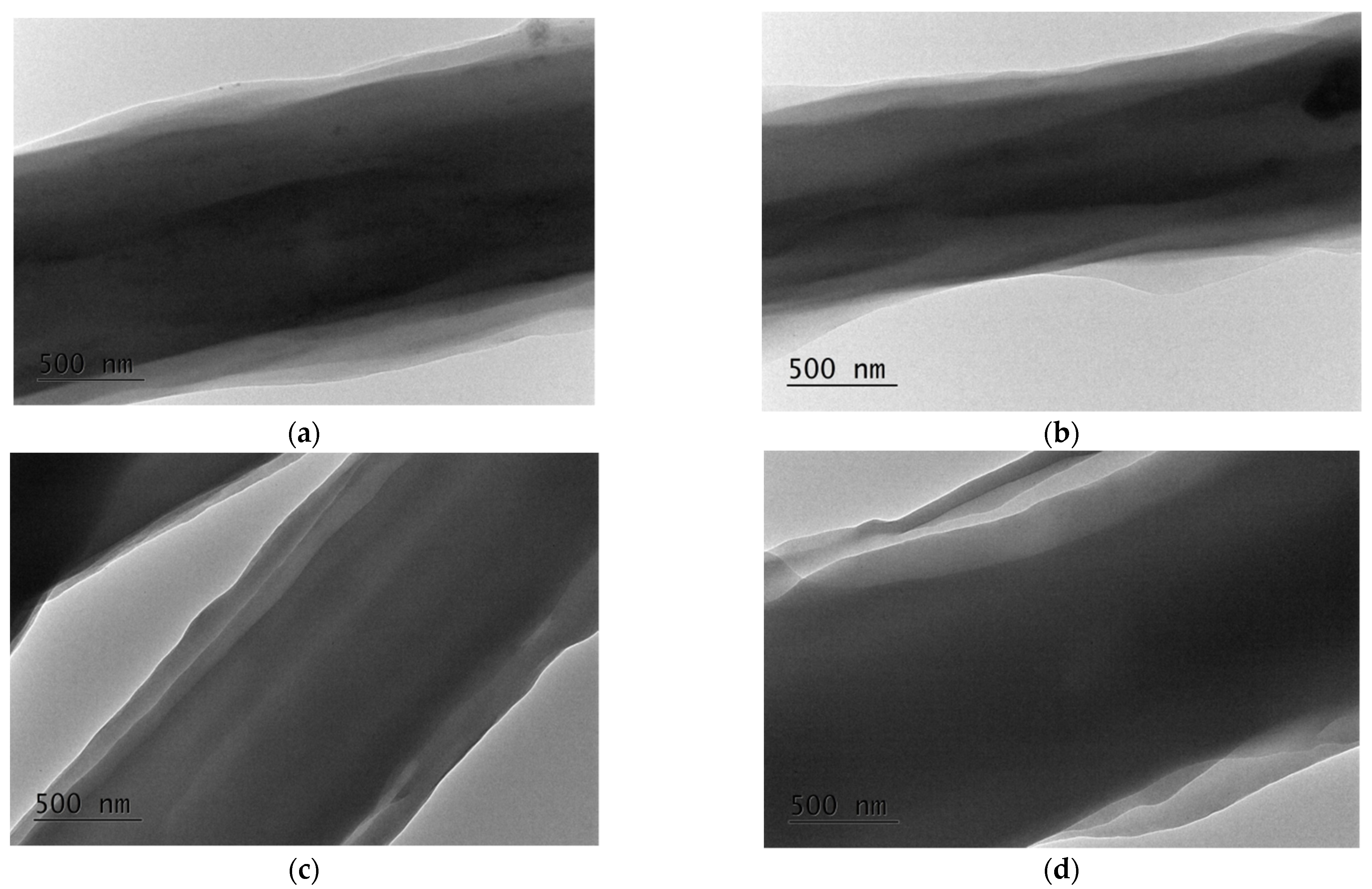
| Specimen | Core Area [µm2] (a) | PLA Sheath [µm2] (a) | BW Sheath [µm2] (a) | Sheath-to-Core Area Ratio |
|---|---|---|---|---|
| PEO(80)/PLA(10)/BW(10) | 1.13 ± 0.15 | 0.14 ± 0.01 | 0.13 ± 0.01 | 0.24 |
| PEO(70)/PLA(15)/BW(15) | 2.70 ± 0.26 | 0.60 ± 0.04 | 0.40 ± 0.03 | 0.37 |
| PEO(60)/PLA(20)/BW(20) | 0.94 ± 0.07 | 0.25 ± 0.02 | 0.21 ± 0.02 | 0.49 |
| PEO(50)/PLA(25)/BW(25) | 1.64 ± 0.16 | 0.33 ± 0.03 | 0.70 ± 0.04 | 0.63 |
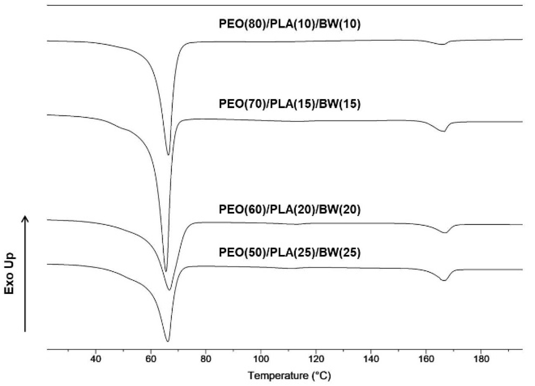
| Specimen | TmPLA [ºC] | ΔHmPLA [J/g] | χcPLA [%] (a) | TmPEO/BW [ºC] | ΔHmPEO/BW [J/g] |
|---|---|---|---|---|---|
| PEO(80)/PLA(10)/BW(10) | 166 | 4.3 | 46 | 65 | 113 |
| PEO(70)/PLA(15)/BW(15) | 166 | 6.4 | 46 | 65 | 109 |
| PEO(60)/PLA(20)/BW(20) | 166 | 8.6 | 46 | 65 | 103 |
| PEO(50)/PLA(25)/BW(25) | 166 | 10.8 | 46 | 65 | 102 |
| Specimen | Inhibition Zone [cm] | |||
|---|---|---|---|---|
| S. aureus | E. coli | P. aeruginosa | C. albicans | |
| PEO(70)/PLA(15)/BW(15) | 3.3 ± 0.1 | 3.5 ± 0.2 | 2.2 ± 0.1 | 3.3 ± 0.3 |
| PEO(50)/PLA(25)/BW(25) | 4.2 ± 0.2 | 3.5 ± 0.2 | 1.9 ± 0.1 | 3.2 ± 0.2 |
Publisher’s Note: MDPI stays neutral with regard to jurisdictional claims in published maps and institutional affiliations. |
© 2022 by the authors. Licensee MDPI, Basel, Switzerland. This article is an open access article distributed under the terms and conditions of the Creative Commons Attribution (CC BY) license (https://creativecommons.org/licenses/by/4.0/).
Share and Cite
Kyuchyuk, S.; Paneva, D.; Manolova, N.; Rashkov, I.; Karashanova, D.; Markova, N. Core/Double-Sheath Composite Fibers from Poly(ethylene oxide), Poly(L-lactide) and Beeswax by Single-Spinneret Electrospinning. Polymers 2022, 14, 5036. https://doi.org/10.3390/polym14225036
Kyuchyuk S, Paneva D, Manolova N, Rashkov I, Karashanova D, Markova N. Core/Double-Sheath Composite Fibers from Poly(ethylene oxide), Poly(L-lactide) and Beeswax by Single-Spinneret Electrospinning. Polymers. 2022; 14(22):5036. https://doi.org/10.3390/polym14225036
Chicago/Turabian StyleKyuchyuk, Selin, Dilyana Paneva, Nevena Manolova, Iliya Rashkov, Daniela Karashanova, and Nadya Markova. 2022. "Core/Double-Sheath Composite Fibers from Poly(ethylene oxide), Poly(L-lactide) and Beeswax by Single-Spinneret Electrospinning" Polymers 14, no. 22: 5036. https://doi.org/10.3390/polym14225036