
Computer Simulation of Composite Materials Behavior under Pressing

 ,
,  ,
,  ,
,
Abstract
:1. Introduction
2. Materials and Methods
2.1. Materials
2.2. Technological Process of Obtaining Composite Materials
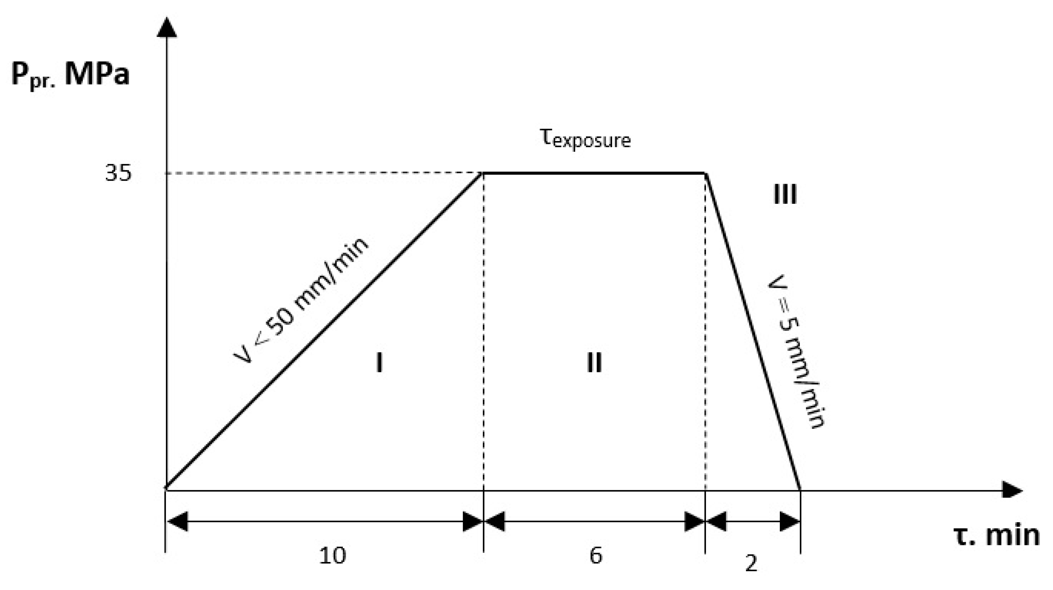
2.2.1. Pressing
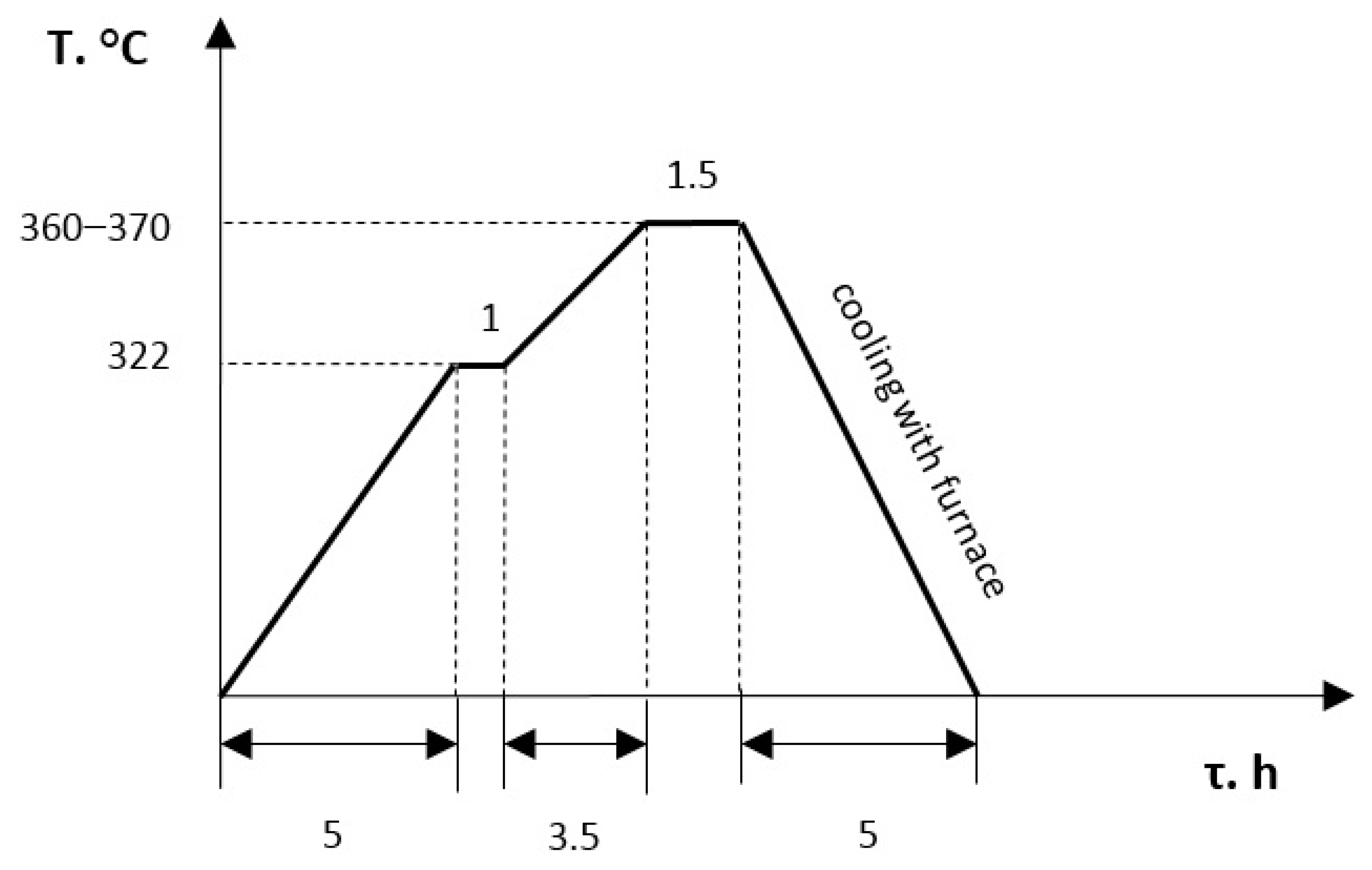
2.2.2. Sintering
3. Numerical Method
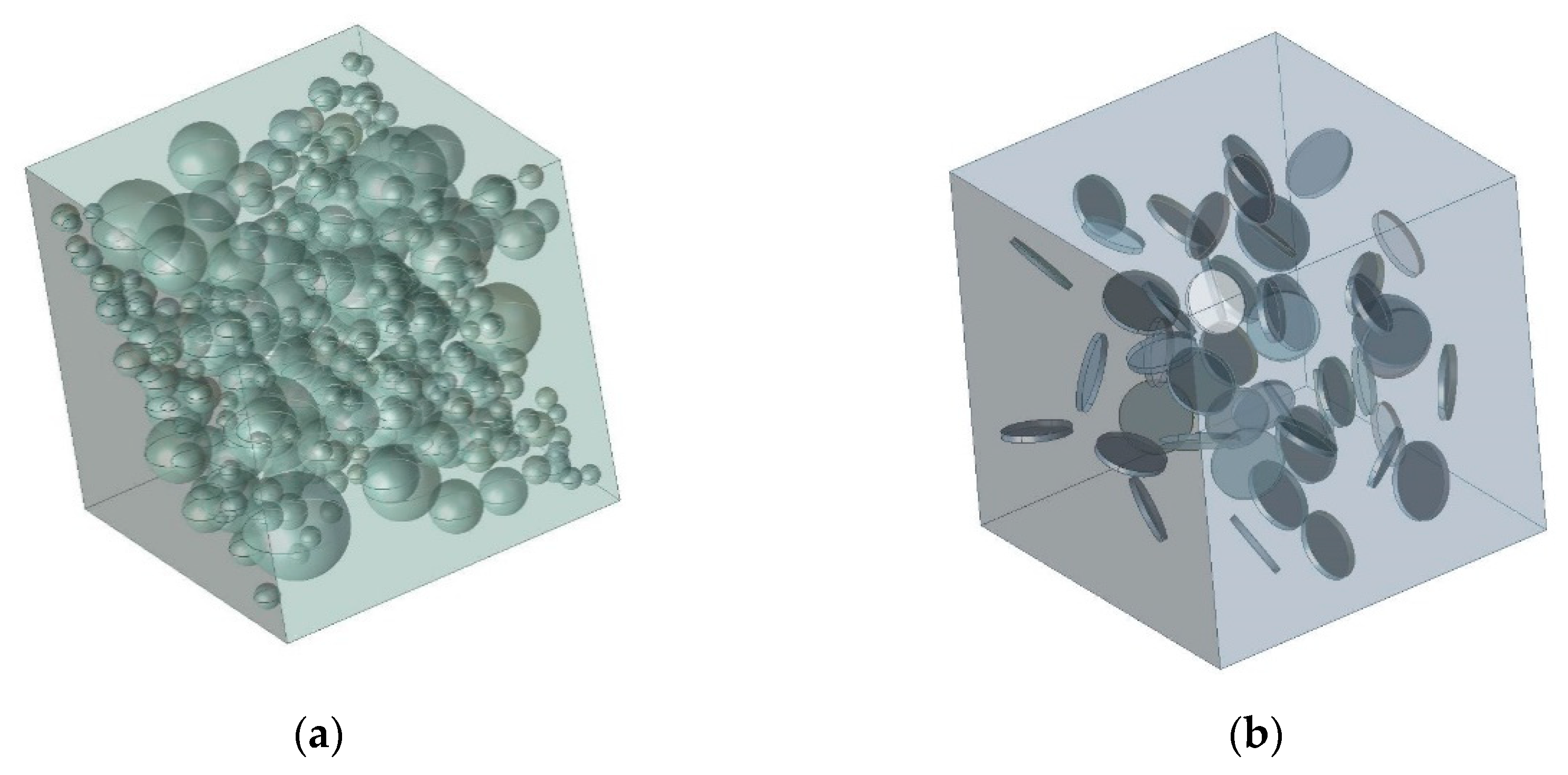
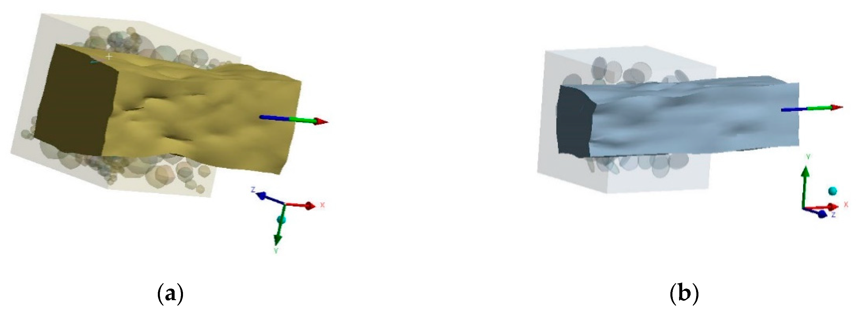
3.1. Construction of a Solid-State Model of a Composite Material
3.1.1. The Spherical Filler
3.1.2. The Short Cylindrical Filler
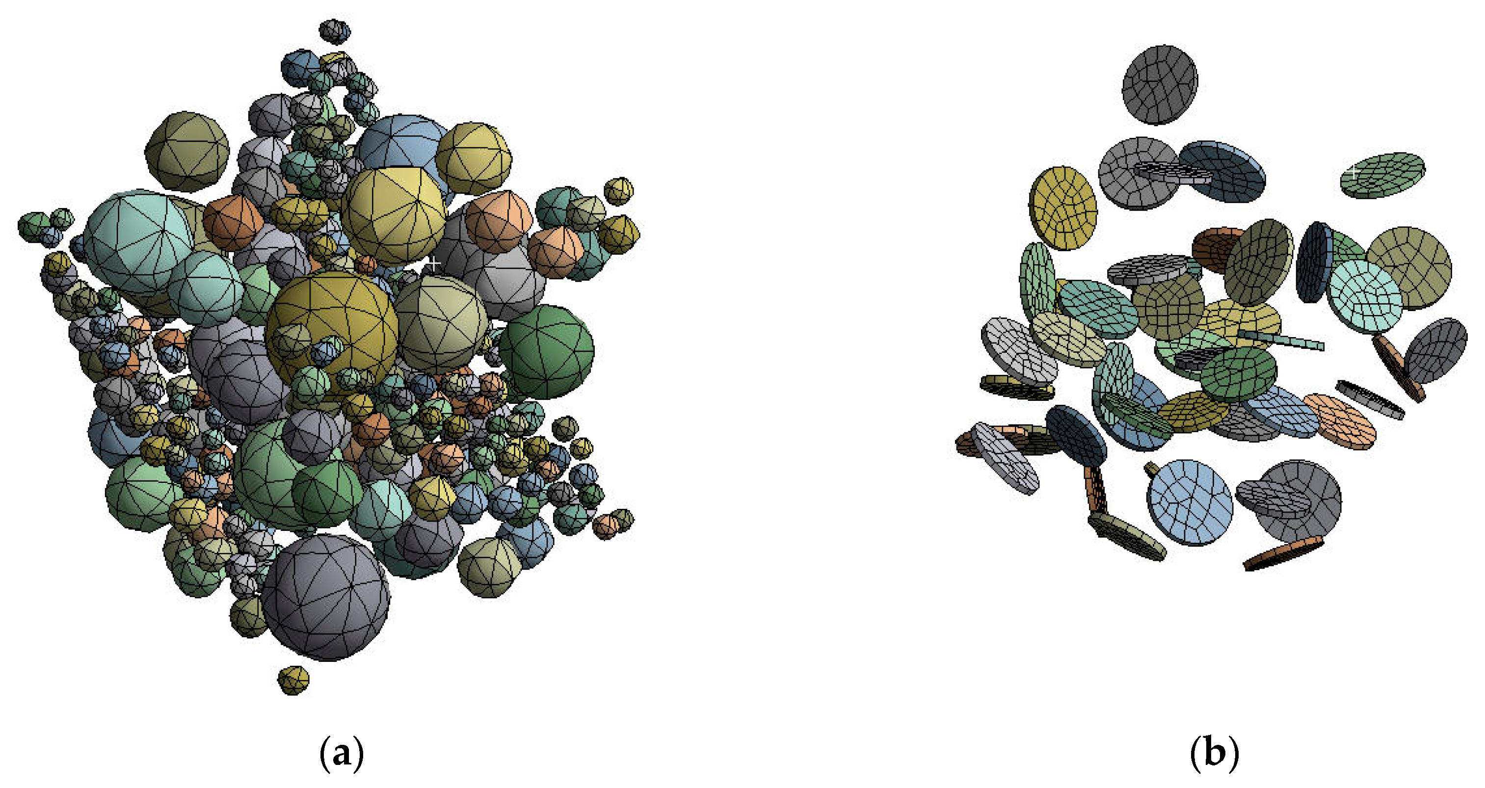
3.2. Construction of a Finite Element Model of a Composite Material
3.2.1. Micromechanical Approach
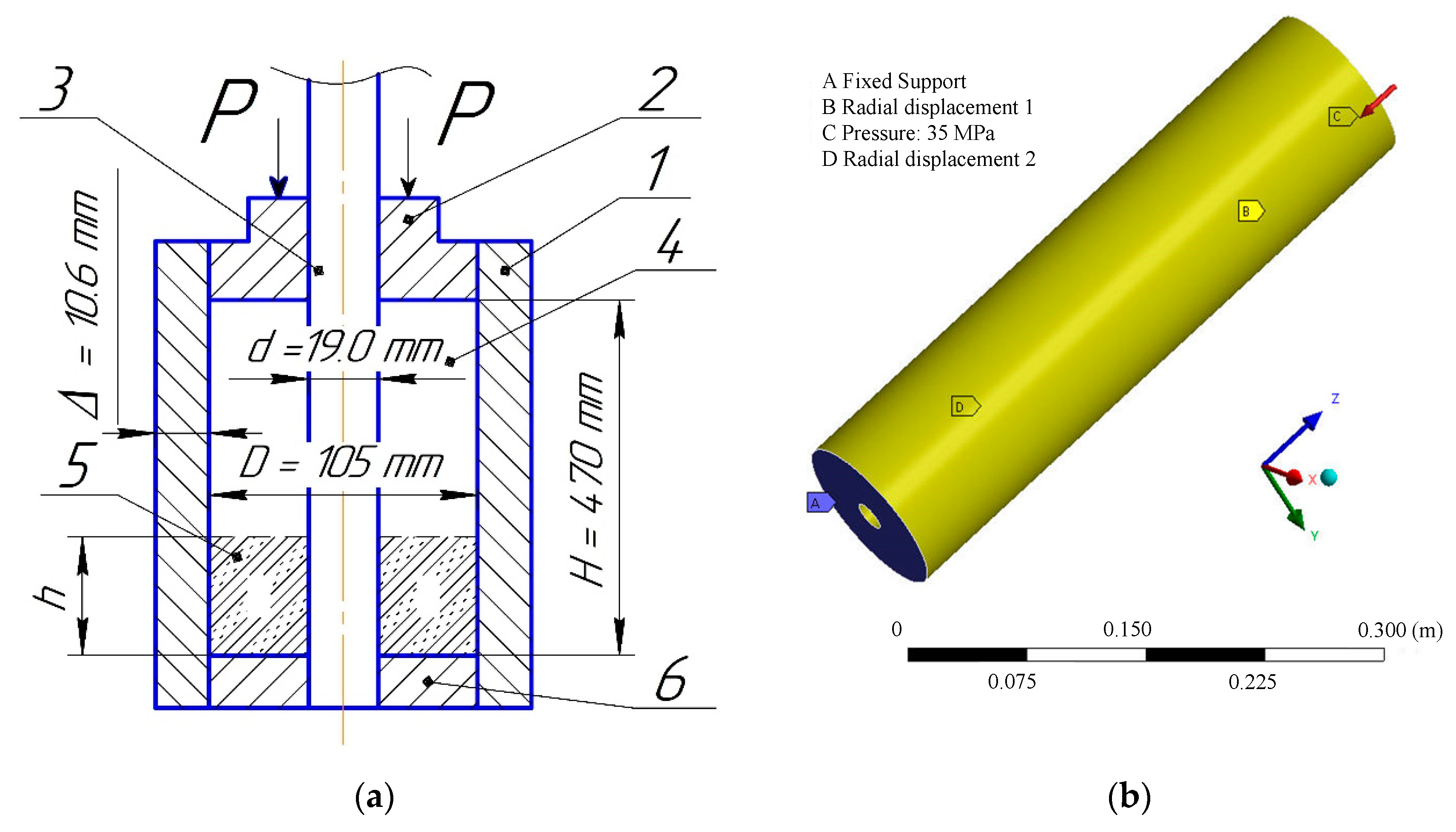
3.2.2. Macromechanical Approach
4. Results and Discussion
4.1. Model Simulation Results
4.2. Verification of the Results of the Micromechanical Approach (First Stage)
4.3. Verification of the Results of the Macromechanical Approach (Second Stage)
5. Conclusions
Author Contributions
Funding
Institutional Review Board Statement
Informed Consent Statement
Data Availability Statement
Acknowledgments
Conflicts of Interest
References
- Torralba, J.M. Improvement of Mechanical and Physical Properties in Powder Metallurgy. In Comprehensive Materials Processing; Hashmi, S., Batalha, G.F., Van Tyne, C.J., Yilbas, B., Eds.; Elsevier: Amsterdam, The Netherlands, 2014; Volume 3, pp. 281–294. [Google Scholar] [CrossRef]
- Wang, Q.B.; Jia, D.L.; Pei, X.H.; Wu, X.L.; Xu, F.; Ye, Z.H.; Wang, H.X. Mechanical performance of graphenex/poly(ether ketone ketone) composite sheets by hot pressing. Sci. Rep. 2022, 12, 4114. [Google Scholar] [CrossRef] [PubMed]
- Grasso, S.; Biesuz, M.; Zoli, L.; Taveri, G.; Duff, A.I.; Ke, D.; Jiang, A.; Reece, M.J. A review of cold sintering processes. Adv. Appl. Ceram. 2020, 119, 115–143. [Google Scholar] [CrossRef] [Green Version]
- Guo, J.; Floyd, R.; Lowum, S.; Maria, J.-P.; Herisson de Beauvoir, T.H.; Seo, J.-H.; Randall, C.A. Cold Sintering: Progress, Challenges, and Future Opportunities. Annu. Rev. Mater. Res. 2019, 49, 275–295. [Google Scholar] [CrossRef]
- Wang, C.; Zhong, W.; Ping, W.; Lin, Z.; Wang, R.; Dai, J.; Guo, M.; Xiong, W.; Zhao, J.-C.; Hu, L. Rapid Synthesis and Sintering of Metals from Powders. Adv. Sci. 2021, 8, 2004229. [Google Scholar] [CrossRef] [PubMed]
- Abdulhameed, O.; Al-Ahmari, A.; Ameen, W.; Mian, S.H. Additive manufacturing: Challenges, trends, and applications. Adv. Mech. Eng. 2019, 11, 1–27. [Google Scholar] [CrossRef] [Green Version]
- Shadangi, Y.; Shivam, V.; Chattopadhyay, K.; Mukhopadhyay, N.K. Powder Metallurgical Processing of Sn-Reinforced Al-Cu-Fe Quasicrystals: Structure, Microstructure and Toughening Behavior. J. Manuf. Mater. Process. 2022, 6, 60. [Google Scholar] [CrossRef]
- Maurya, H.S.; Kollo, L.; Tarraste, M.; Juhani, K.; Sergejev, F.; Prashanth, K.G. Effect of the Laser Processing Parameters on the Selective Laser Melting of TiC–Fe-Based Cermets. J. Manuf. Mater. Process. 2022, 6, 35. [Google Scholar] [CrossRef]
- Zhang, X.; Xu, Y.; Wang, M.; Liu, E.; Zhao, N.; Shi, C.; Lin, D.; Zhu, F.; He, C. A powder-metallurgy-based strategy toward three-dimensional graphene-like network for reinforcing copper matrix composites. Nat. Commun. 2020, 11, 2775. [Google Scholar] [CrossRef]
- Friedrich, K. Polymer composites for tribological applications. Adv. Ind. Eng. Polym. Res. 2018, 1, 3–39. [Google Scholar] [CrossRef]
- Conte, M.; Igartua, A. Study of PTFE composites tribological behavior. Wear 2012, 296, 568–574. [Google Scholar] [CrossRef]
- Budnik, O.A.; Sviderskii, V.A.; Budnik, A.F.; Berladir, K.V.; Rudenko, P.V. Composite Material for Chemical and Petrochemical Equipment Friction Assemblies. Chem. Petrol. Eng. 2016, 52, 63–68. [Google Scholar] [CrossRef]
- Bilous, O.A.; Hovorun, T.P.; Berladir, K.V.; Vorobiov, S.I.; Simkulet, V.V. Mathematical modeling of the mechanical characteristic of the activated PTFE-matrix using the method of planning the experiment. J. Eng. Sci. 2018, 5, C1–C5. [Google Scholar] [CrossRef] [Green Version]
- Zhao, Z.H.; Chen, J.N. Preparation of single-polytetrafluoroethylene composites by the processes of compression molding and free sintering. Compos. Part B Eng. 2011, 42, 1306–1310. [Google Scholar] [CrossRef]
- Berladir, K.V.; Sviderskiy, V.A. Designing and examining polytetrafluoroethylene composites for tribotechnical purposes with activated ingredients. East.-Eur. J. Enterp. Technol. 2016, 6, 14–21. [Google Scholar] [CrossRef]
- Tang, X.Z.; Wang, Z.J.; Yi, J.; Han, Y.Y.; Wang, Y.F.; Jia, Z.J. Experimental study of hot pressed sintered modified materials. J. Phys. Conf. Ser. 2020, 1507, 032061. [Google Scholar] [CrossRef]
- Poitou, B.; Dore, F.; Champomier, R. Mechanical and physical charactersations of polytetrafluoroethylene by high velocity compaction. Int. J. Mater. Form. 2009, 2, 657. [Google Scholar] [CrossRef]
- Wang, Y.; Jiang, C.; Wang, Z. Effect of Sintering Factors on Properties of Al-Rich PTFE/Al/TiH2 Active Materials. Polymers 2021, 13, 1705. [Google Scholar] [CrossRef] [PubMed]
- Tang, X.; Wang, Z.; Zhang, X.; Xu, Y.; Yi, J. Comparative study on microstructure and properties of different designed PTFE/Cu materials. J. Mater. Res. Technol. 2022, 17, 1512–1521. [Google Scholar] [CrossRef]
- Tóth, L.F.; Baets, P.D.; Szebényi, G. Processing Analysis of Nanoparticle Filled PTFE: Restrictions and Limitations of High Temperature Production. Polymers 2020, 12, 2044. [Google Scholar] [CrossRef]
- Zhang, S.; Li, Q.; Che, Y.; Wu, C.; Guo, W. Preparation and Properties of Composites of Carbon Black Reinforced Polytetrafluoroethylene Prepared by a Two-step Process. Chin. J. Mater. Res. 2017, 31, 847–852. [Google Scholar] [CrossRef]
- Chung, S.H.; Kwon, Y.; Park, S.J.; German, R.M. Modeling and Simulation of Press and Sinter Powder Metallurgy. In Metals Process Simulation; Furrer, D.U., Semiatin, S.L., Eds.; ASM International: Novelty, OH, USA, 2010; Volume 22B, pp. 323–334. [Google Scholar] [CrossRef]
- Minh, P.S.; Nguyen, V.T.; Nguyen, V.T.; Uyen, T.M.T.; Do, T.T.; Nguyen, V.T.T. Study on the Fatigue Strength of Welding Line in Injection Molding Products under Different Tensile Conditions. Micromachines 2022, 13, 1890. [Google Scholar] [CrossRef] [PubMed]
- Singh, M.; Sharma, S.; Muniappan, A.; Pimenov, D.Y.; Wojciechowski, S.; Jha, K.; Dwivedi, S.P.; Li, C.; Królczyk, J.B.; Walczak, D.; et al. In Situ Micro-Observation of Surface Roughness and Fracture Mechanism in Metal Microforming of Thin Copper Sheets with Newly Developed Compact Testing Apparatus. Materials 2022, 15, 1368. [Google Scholar] [CrossRef]
- Thuong Huynh, T.; Nguyen, T.V.T.; Manh Nguyen, Q.; Khoa Nguyen, T. Minimizing warpage for macro-size fused deposition modeling parts. Comput. Mater. Contin. 2021, 68, 2913–2923. [Google Scholar] [CrossRef]
- Chen, S.; Xu, Y.; Jiao, Y. Modeling solid-state sintering with externally applied pressure: A geometric force approach. AIMS Mater. Sci. 2017, 4, 75–88. [Google Scholar] [CrossRef]
- Nosewicz, S.; Rojek, J.; Chmielewski, M.; Pietrzak, K. Discrete Element Modeling of Intermetallic Matrix Composite Manufacturing by Powder Metallurgy. Materials 2019, 12, 281. [Google Scholar] [CrossRef] [Green Version]
- Nosewicz, S.; Rojek, J.; Chmielewski, M. Discrete Element Framework for Determination of Sintering and Postsintering Residual Stresses of Particle Reinforced Composites. Materials 2020, 13, 4015. [Google Scholar] [CrossRef]
- Rajaei, A.; Deng, Y.; Schenk, O.; Rooein, S.; Bezold, A.; Broeckmann, C. Numerical Modelling of the Powder Metallurgical Manufacturing Chain of High Strength Sintered Gears. Chin. J. Mech. Eng. 2021, 34, 143. [Google Scholar] [CrossRef]
- Matsuda, T. Distortion prediction during sintering using Monte Carlo method implemented with virtual springs. Int. J. Ceram. Eng. Sci. 2022, 4, 270–280. [Google Scholar] [CrossRef]
- Zhanga, Y.; Xiaob, X.; Zhanga, J. Kinetic Monte Carlo simulation of sintering behavior of additively manufactured stainless steel powder particles using reconstructed microstructures from synchrotron X-ray microtomography. Results Phys. 2019, 13, 102336. [Google Scholar] [CrossRef]
- Reiterera, M.; Krafta, T.; Janosovitsb, U.; Riedela, H. Finite element simulation of cold isostatic pressing and sintering of SiC components. Ceram. Int. 2004, 30, 177–183. [Google Scholar] [CrossRef]
- Zhu, Y.; Li, N.; Li, W.; Niu, L.; Li, Z. Atomistic Study on the Sintering Process and the Strengthening Mechanism of Al-Graphene System. Materials 2022, 15, 2644. [Google Scholar] [CrossRef] [PubMed]
- Cricrì, G.; Perrella, M. Modelling the mechanical behaviour of metal powder during Die compaction process. Frattura Integr. Strutt. 2016, 37, 333–341. [Google Scholar] [CrossRef] [Green Version]
- Wikman, B.; Svoboda, A.; Häggblad, H.-Å. A combined material model for numerical simulation of hot isostatic pressing. Comput. Methods Appl. Mech. Eng. 2000, 189, 901–913. [Google Scholar] [CrossRef]
- Qiu, H.; Zhu, Y.G.; Zhang, L. Thermal Stress Analysis of Powder Metallurgy Sintering Process Based on ANSYS. KEM 2015, 667, 3244–3249. [Google Scholar] [CrossRef]
- He, H.; Wang, J.; Li, S.; Chen, Z.; Sun, J.; You, Y. Temperature Field Simulation of Powder Sintering Process with ANSYS. IOP Conf. Ser. Mater. Sci. Eng. 2015, 324, 012008. [Google Scholar] [CrossRef]
- Guenoun, G.; Faou, J.-Y.; Régnier, G.; Schmitt, N.; Roux, S. Thermal cycling of cold-pressed PTFE compacts: Reversible and irreversible behavior. Polym. Test. 2019, 75, 99–106. [Google Scholar] [CrossRef] [Green Version]
- Luo, C.; Pei, J.; Zhuo, W.; Niu, Y.; Lia, G. Phase transition behavior and deformation mechanism of polytetrafluoroethylene under stretching. RSC Adv. 2021, 11, 39813–39820. [Google Scholar] [CrossRef]
- Sumitani, Y.; Ono, Y.; Saito, Y.; Matsushita, Y.; Aoki, H.; Shishido, T.; Okuyama, N. Effect of Changes in Mechanical Properties of Coke Matrix Caused by CO2 or H2O Gasification Reaction on the Strength of Lump Coke. ISIJ Int. 2021, 61, 119–128. [Google Scholar] [CrossRef]
- Yang, H.; Han, Z.; Hu, J.; He, M. Defect and temperature effects on the mechanical properties of kaolinite: A molecular dynamics study. Clay Miner. 2019, 54, 153–159. [Google Scholar] [CrossRef]
- Berladir, K.V.; Budnik, O.A.; Dyadyura, K.A.; Svidersky, V.A.; Kravchenko, Y.O. Physicochemical principles of polymer composite materials technology based on polytetrafluoroethylene. High Temp. Mater. Process. 2016, 20, 157–184. [Google Scholar] [CrossRef]
- Talamadupula, K.K.; Seidel, G. Computational Micromechanics Investigation of Percolation and Effective Electro-Mechanical Properties of Carbon Nanotube/Polymer Nanocomposites using Stochastically Generated Realizations: Effects of Orientation and Waviness. Polymers 2022, 14, 5094. [Google Scholar] [CrossRef]
- Muhlestein, M.B.; Haberman, M.R. A micromechanical approach for homogenization of elastic metamaterials with dynamic microstructure. Proc. R. Soc. A 2016, 472, 20160438. [Google Scholar] [CrossRef] [Green Version]
- Yun, J.-H.; Jeon, Y.-J.; Kang, M.-S. Prediction of Elastic Properties Using Micromechanics of Polypropylene Composites Mixed with Ultrahigh-Molecular-Weight Polyethylene Fibers. Molecules 2022, 27, 5752. [Google Scholar] [CrossRef]
- Galindo-Torres, S.A.; Scheuermann, A.; Mühlhaus, H.B.; Williams, D.J. A micro-mechanical approach for the study of contact erosion. Acta Geotech. 2015, 10, 357–368. [Google Scholar] [CrossRef]
- Fajardo, J.I.; Costa, J.; Cruz, L.J.; Paltán, C.A.; Santos, J.D. Micromechanical Model for Predicting the Tensile Properties of Guadua angustifolia Fibers Polypropylene-Based Composites. Polymers 2022, 14, 2627. [Google Scholar] [CrossRef]
- Leon-Becerra, J.; González-Estrada, O.A.; Sánchez-Acevedo, H. Comparison of Models to Predict Mechanical Properties of FR-AM Composites and a Fractographical Study. Polymers 2022, 14, 3546. [Google Scholar] [CrossRef]
- Mamache, F.E.; Mesbah, A.; Bian, H.; Zaïri, F. Micromechanical Modeling of the Biaxial Deformation-Induced Phase Transformation in Polyethylene Terephthalate. Polymers 2022, 14, 3028. [Google Scholar] [CrossRef] [PubMed]
- Sayyidmousavi, A.; Fawaz, Z. A micromechanical approach to the mechanical characterization of 3D-printed composites. Polym. Polym. Compos. 2022, 30, 1–7. [Google Scholar] [CrossRef]
- Sharma, A.; Devi, M. A Review on Multiscale Modelling and Simulation for Polymer Nanocomposites. Preprints 2022, 2022020213. [Google Scholar] [CrossRef]
- Pozovnyi, O.; Deineka, A.; Lisovenko, D. Calculation of hydrostatic forces of multi-gap seals and its dependence on shaft displacement. In Proceedings of the Advances in Design, Simulation and Manufacturing II, DSMIE 2019 (Lecture Notes in Mechanical Engineering), Lutsk, Ukraine, 11–14 June 2019. [Google Scholar]


| Designation | Material | Size, μm | Density, kg·m−3 | Modulus of Elasticity, MPa | Poisson’s Ratio |
|---|---|---|---|---|---|
| Matrix | PTFE | 50–500 | 2200 | 686.5 | 0.45 |
| Spherical inclusions | Coke | 10–50 | 1730 | 500 | 0.30 |
| Short cylindrical inclusions | Kaolin | up to 10 | 2350 | 92000 | 0.18 |
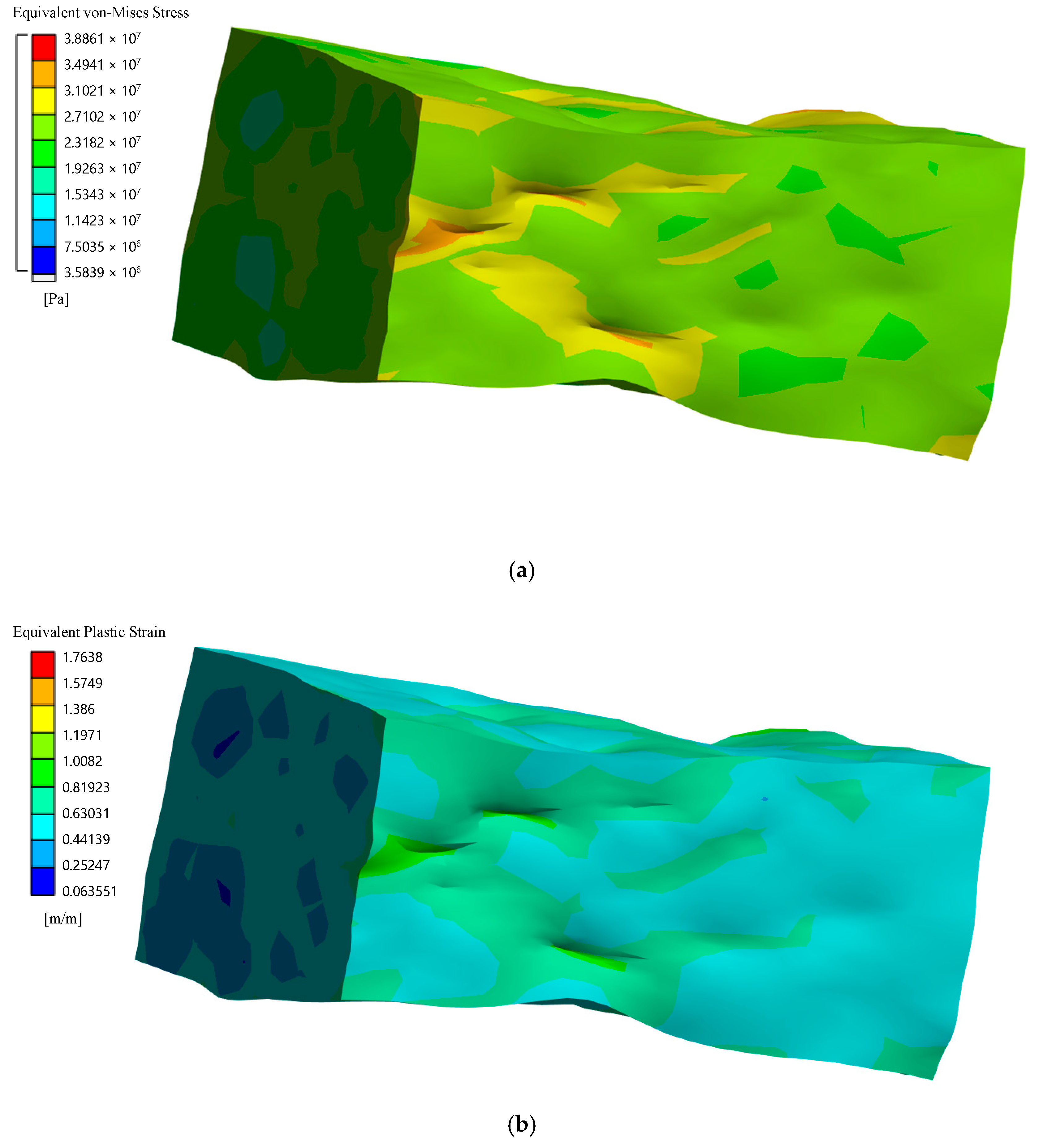
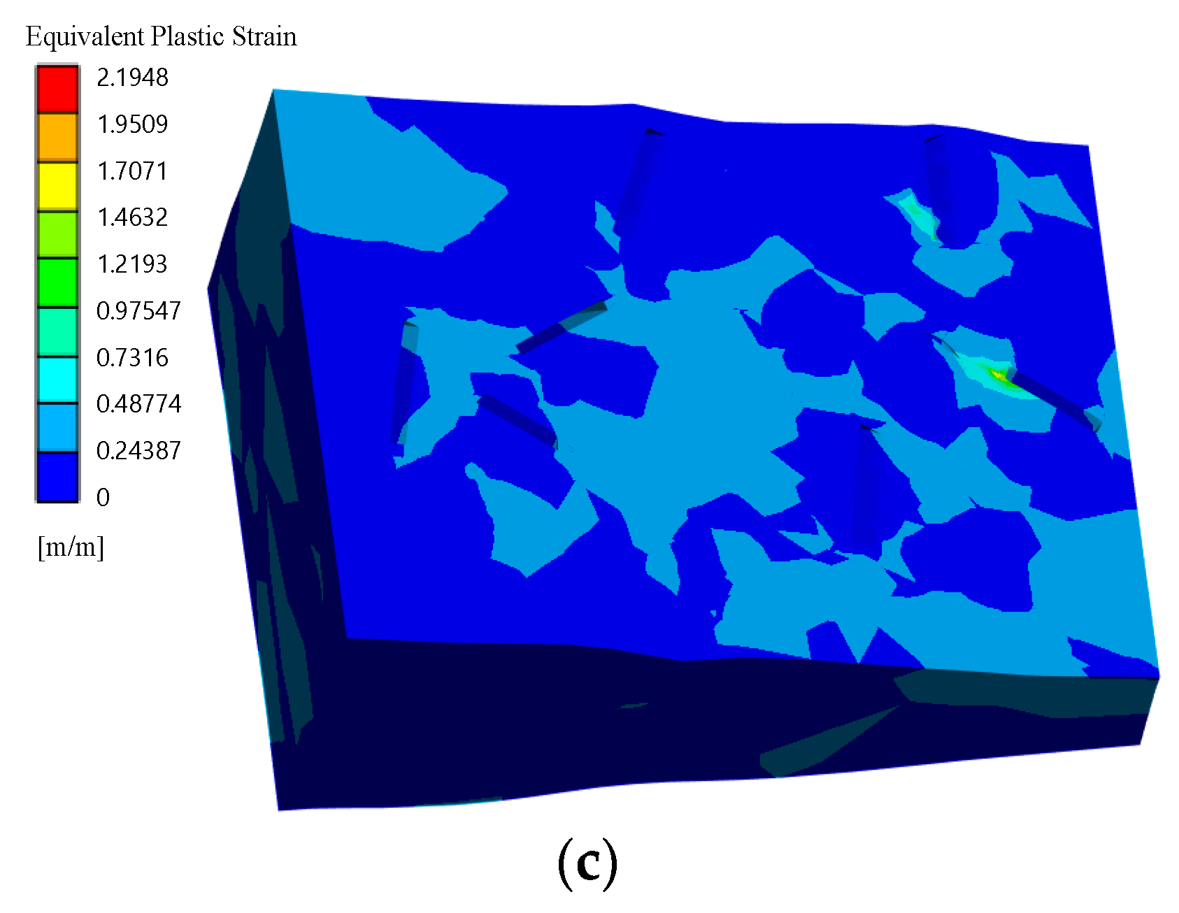
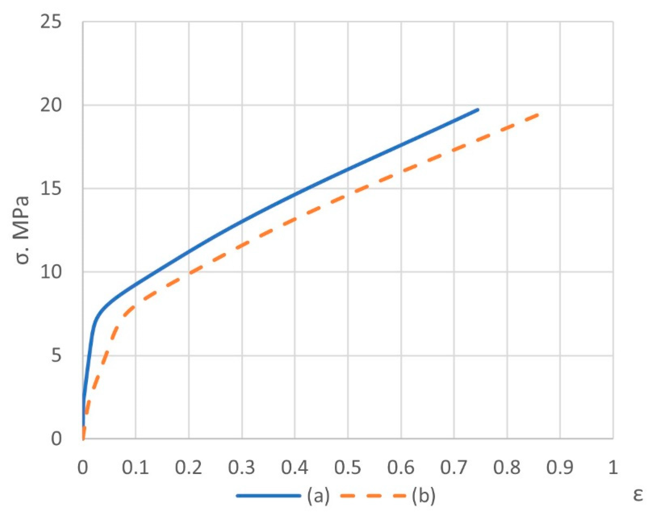
| Composition (Matrix/Filler) | Mass/Volume Fractions of Matrix and Filler | The Shape of the Filler | Ultimate Strength Simulation/Experiment, MPa | Average Ultimate Total Strain, % | Average Ultimate Plastic Strain, % | Poisson’s Ratio |
|---|---|---|---|---|---|---|
| PTFE + coke | 80:20/75.88:24.12 | spherical | 19.72/18.6 | 88.34 | 73.55 | 0.406 ± 0.005 |
| PTFE + kaolin | 98:2/98.13:1.87 | short cylindrical | 17.86/17.8 | 28.49 | 18.18 | 0.445 ± 0.005 |
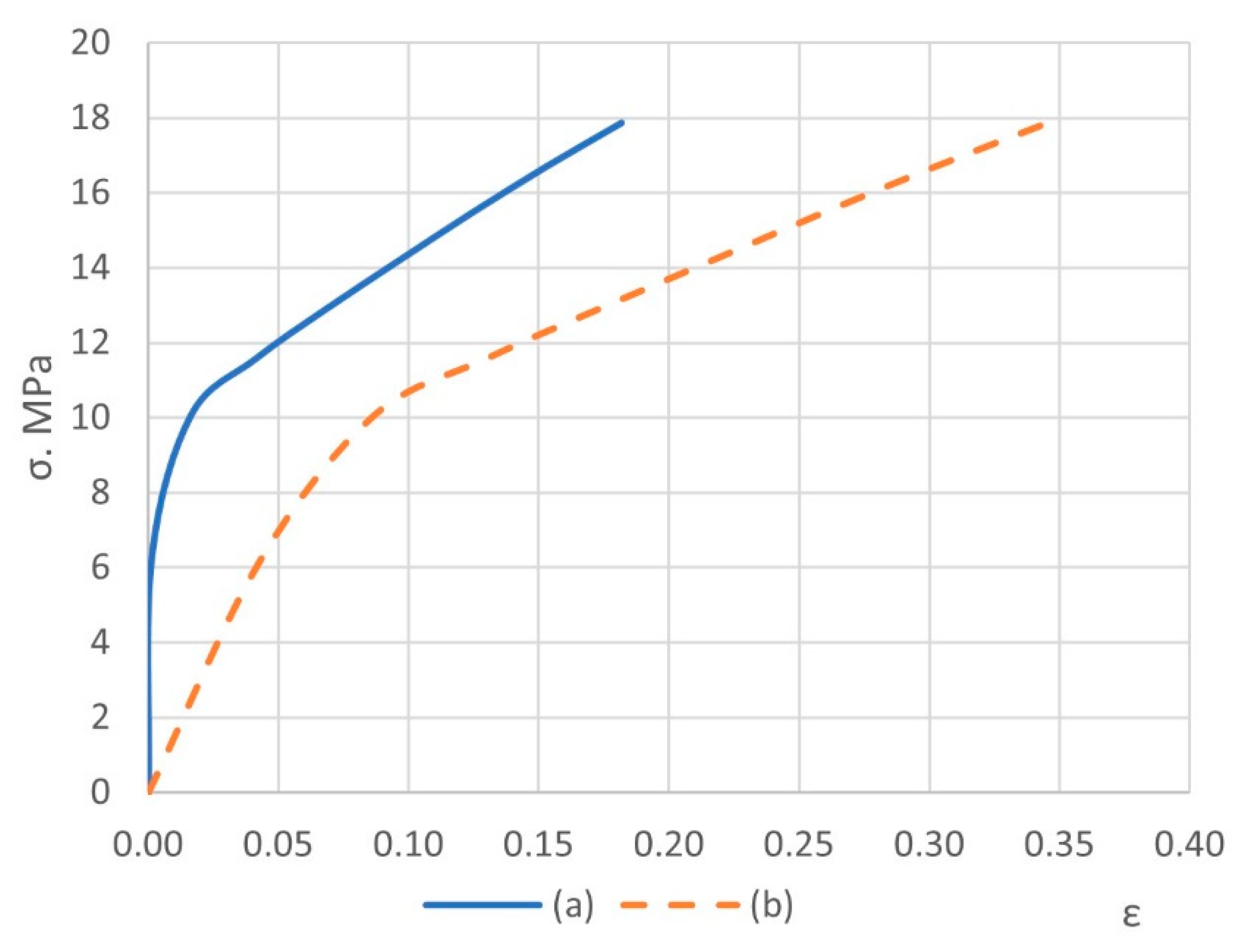
| Composition (Matrix/Filler) | After Mechanical Processing (Simulation Data) | After Heat Treatment (Experimental Data) | ||
|---|---|---|---|---|
| Average Total Strain under 35 MPa Pressure, % | Average Plastic Strain under 35 MPa Pressure, % | Total Strain Capacity after Unloading, % | Total Strain Capacity, % | |
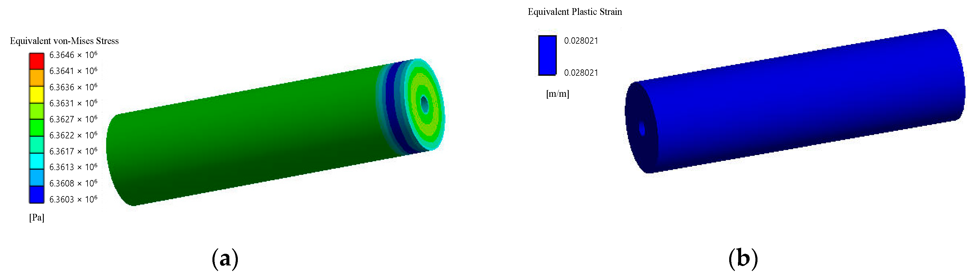
| PTFE + coke | 5.9844 | 2.8021 | 88.34 − 2.80 = 85.54 | 115 |
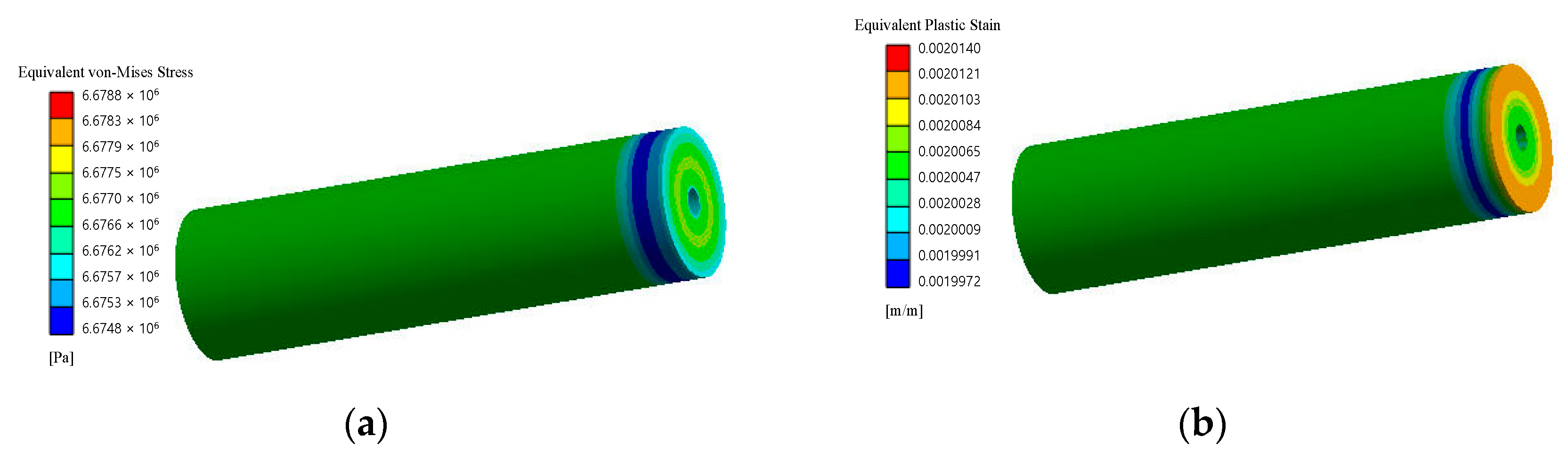
| PTFE + kaolin | 1.4363 | 0.20061 | 28.49 − 0.20 = 28.29 | 432 |
Publisher’s Note: MDPI stays neutral with regard to jurisdictional claims in published maps and institutional affiliations. |
© 2022 by the authors. Licensee MDPI, Basel, Switzerland. This article is an open access article distributed under the terms and conditions of the Creative Commons Attribution (CC BY) license (https://creativecommons.org/licenses/by/4.0/).
Share and Cite
Berladir, K.; Zhyhylii, D.; Brejcha, J.; Pozovnyi, O.; Krmela, J.; Krmelová, V.; Artyukhov, A. Computer Simulation of Composite Materials Behavior under Pressing. Polymers 2022, 14, 5288. https://doi.org/10.3390/polym14235288
Berladir K, Zhyhylii D, Brejcha J, Pozovnyi O, Krmela J, Krmelová V, Artyukhov A. Computer Simulation of Composite Materials Behavior under Pressing. Polymers. 2022; 14(23):5288. https://doi.org/10.3390/polym14235288
Chicago/Turabian StyleBerladir, Khrystyna, Dmytro Zhyhylii, Jiří Brejcha, Oleksandr Pozovnyi, Jan Krmela, Vladimíra Krmelová, and Artem Artyukhov. 2022. "Computer Simulation of Composite Materials Behavior under Pressing" Polymers 14, no. 23: 5288. https://doi.org/10.3390/polym14235288