1. Introduction
In civil infrastructures, many reinforced concrete (RC) structures cannot meet structural requirements. Cracking could be caused by many combined factors, such as concrete carbonation, steel corrosion, excessive deflections due to prestress loss, shrinkage, and creep of concrete [
1,
2]. Strengthening these infrastructures has become necessary to increase structural safety and service life. In past decades, the strengthening technique based on fiber-reinforced polymer (FRP) has been an acceptable technique for strengthening RC structures due to advantages, such as the light weight, high strength, good corrosion, and fatigue resistance of FRP materials [
3,
4,
5,
6,
7,
8,
9,
10]. Among the different types of FRP materials, carbon–FRP (CFRP) is preferred, and the application forms of the CFRP in the strengthening of RC structures mainly include externally bonded (EB) CFRP laminates [
11,
12,
13,
14,
15,
16], near-surface-mounted (NSM) CFRP bars/strips [
17], and externally prestressed CFRP bars/cables [
18]. Among these strengthening methods, EB–CFRP technology is most widely used for strengthening RC structures. Extensive studies have been carried out on the flexural behavior of RC beams strengthened with EB–CFRP. When using the EB–CFRP technique for strengthening RC structures, one of the main issues is the premature debonding of the CFRP. When debonding occurs, the tensile strain of the CFRP is low, meaning that its tensile strength cannot be fully used [
19,
20]. In addition, many studies have shown that the ultimate capacity of strengthened RC beams can be improved by using CFRP laminates. In contrast, the flexural performance under normal service conditions slightly increases [
21,
22].
There are usually two types of methods used to postpone and even prevent the debonding process. The first method is to limit the debonding strain of the CFRP, which greatly decreases the allowable improvement of the flexural-load-carrying capacity [
20]. The other method is to use an anchorage device at two ends of the CFRP laminate [
23]. Different anchorage devices have been used in studies, such as mechanically fastened metallic anchors, U-jacket anchors, and FRP spike anchors [
23,
24,
25,
26,
27]. Studies have shown that the use of FRP U-jackets at the FRP ends could change the failure mode from concrete cover separation and end-debonding to intermediate crack-induced (IC) debonding at higher loads, and the FRP U-jackets along the beam length at certain spacing could postpone the occurrence of IC debonding [
24,
28,
29]. However, a study conducted by Khan et al. [
30] found that the ultimate load-carrying capacity of the specimens strengthened with CFRP sheets increased by only 5.8% using CFRP wraps at two ends of the CFRP sheets, indicating that CFRP wraps had little effect on improving the strengthening efficacy. Spadea et al. [
31] used a U-shaped steel anchor to improve the flexural behavior of RC beams strengthened with CFRP plates and found that the CFRP strain reached a 67% enhancement over the unanchored specimen. A study conducted by Wu and Huang [
25] showed that specimens strengthened with 2-ply and 4-ply sheets failed due to CFRP rupture when combinations of EB–FRP and mechanical steel fasteners were used. Recently, Eslami et al. [
32] developed a novel anchorage system of CFRP sheets by squeezing CFRP sheets into the groove at the ends of RC beams, and test results confirmed the efficacy of the proposed end anchorage technique. Generally, although several novel anchorage methods have been developed, the widely used anchorage methods in practical engineering are still FRP U-jackets and mechanically fastened steel plates. However, more studies should be conducted to assess the anchorage performance in large-scale girders with beam widths greater than 300 mm since most existing studies have used relatively narrow beam widths [
23].
To increase the strength usage of the CFRP laminate and improve the structural behavior under normal service conditions, many studies have been carried out on the use of the prestressed CFRP laminate, and the effectiveness on flexural strengthening of RC beams has been validated [
3,
33,
34,
35,
36,
37,
38]. The prestressing method is critical for the prestressed CFRP strengthening technique. Different methods have been developed to tension CFRP laminates. The first method is an indirect method. The strengthened beam is first cambered before bonding the CFRP, and then prestress is applied by releasing the camber after bonding and curing the CFRP [
39]. However, the application of prestress is difficult, and the prestressing level is low in this method. These drawbacks limit its application in practical engineering [
21,
38,
40]. The second method is to prestress the CFRP laminate using an independent external frame [
33,
34,
41,
42,
43], which also belongs to an indirect method. After tensioning the CFRP, the CFRP is bonded on the surface of the member and then cured, followed by cutting the CFRP from the external anchors. This method is widely used in small-scale beams in the laboratory, but using heavy external equipment could be unrealistic in practical engineering [
40]. The third method is to directly tension the CFRP laminate against the strengthened beam itself [
3,
21,
38]. This method can be conveniently used in practical engineering [
21]. However, the majority of previous studies have used the second method. Therefore, more studies need to be conducted on developing practical prestressing systems and evaluating their efficacy in strengthening RC beams.
Although many studies have investigated the flexural behavior of RC beams strengthened with nonprestressed and prestressed CFRP materials, a literature review found that further studies should be conducted to promote the application of the EB–CFRP technique. First, small-scale specimens were always used in previous studies to verify the anchorage efficiency of anchorage methods (especially FRP U-jackets and mechanically fastened steel plates). The anchorage efficiency should be further investigated using large-scale specimens. Second, most prestressing methods used in previous studies required a special reaction frame, which could be unrealistic in practical applications. More prestressing systems for practical applications should be presented and validated. Third, when RC beams are strengthened with the EB–CFRP technique, some choices have to be made, such as a CFRP plate or sheet, the CFRP to be prestressed or not, and the anchorage method/device of the CFRP. However, a direct comparison between the strengthening efficacies of different EB–CFRP methods is still lacking in the references. Therefore, an experimental study was conducted using seven large-scale RC specimens in this study. Three different anchorage methods were compared, and two practical prestressing systems with different anchors and tensioning methods were used. The effects of the anchorage method, CFRP type, prestress, and prestressing system on the flexural strengthening efficacy of RC beams were compared and analyzed. The findings of this paper can provide a reference for the engineering application of the EB–CFRP technique.
4. Theoretical Calculation
For the nonprestressed and the prestressed CFRP strengthening technique, a design code [
50] has been proposed to guide practical applications. The ultimate capacity can be calculated according to the basic equations in the code [
50]. In this study, the compressive zone of the concrete was located in the top flange due to a small reinforcement ratio. Therefore, the ultimate bending moment of the strengthened specimens can be calculated based on Equations (1) and (2):
where
Mu is the ultimate bending moment;
fc is the concrete compressive strength;
is the width of the flange;
x is the height of the compressive concrete;
h0 is the distance between the action point of the resultant force of tensile rebars and the compressive edge;
and
are the cross-sectional area and yielding stress of compressive rebars, respectively;
a′ is the distance between the action point of the resultant force of compressive rebars and the compressive edge;
σf is the tensile stress of the CFRP laminate when the ultimate limit state is reached;
Af is the cross-sectional area of the CFRP laminate;
hfe is the distance between the action point of the resultant force of the CFRP laminate and the compressive edge; and
As and
fy are the cross-sectional area and yielding stress of tensile rebars, respectively. For the nonprestressed CFRP laminate, its tensile stress
σf can be determined using Equations (3)–(5):
where
ff is the tensile strength of the CFRP laminate;
Ef is the Young’s modulus of the CFRP laminate;
εfe is the effective tensile strain of the CFRP laminate when the concrete strain at the compressive edge reaches the ultimate compressive strain;
εcu is the ultimate compressive strain of the concrete, which is taken as 0.0033; and
h is the height of the RC beam.
For the prestressed CFRP plate, its tensile stress
σf can be determined using the following equation:
where
εfe is calculated using Equations (3)–(5) and
εfp0 is the tensile strain of the prestressed CFRP plate when the stress of the concrete at the bottom edge is zero.
After obtaining the ultimate bending moment, the ultimate load can be calculated based on the following equation:
where
Pu is the ultimate load and
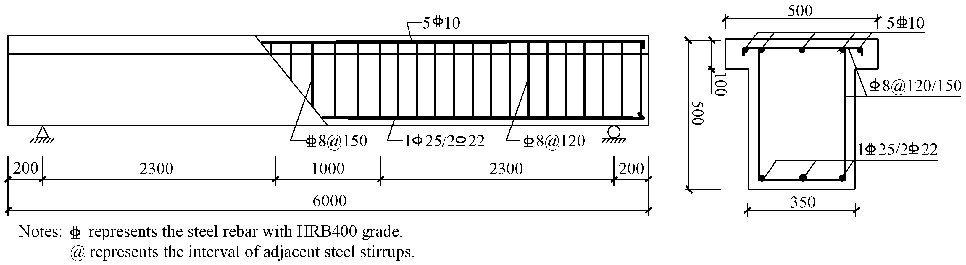
a is the length of the shear span, i.e., 2300 mm in this study.
The calculated and tested ultimate loads are compared in
Table 6, where
δ represents the relative error between the predicted and tested results. It can be seen that the calculated results agree well with the tested results for the nonprestressed and prestressed CFRP strengthened specimens with concrete crushing failure. However, for specimens with end-debonding failure, the calculated results significantly overestimated the ultimate capacity of the specimens. This further demonstrates that an effective anchorage is critical for the EB–CFRP strengthening technique and premature end-debonding failure should be avoided in practical applications.
5. Conclusions
An experimental study was conducted to compare the flexural behavior of RC beams strengthened with nonprestressed and prestressed CFRP materials using different anchorages. The influences of the anchorage method, CFRP type, prestress and prestressing system on the flexural strengthening efficacy were investigated. Based on the limited tests, the following conclusions can be drawn:
- (1)
Two failure modes were observed for the specimens attributed to the different anchorage methods used. The CFRP end-debonding failure occurred in the specimens anchored by CFRP U-wraps or steel plates. In contrast, the compressive concrete crushing failure occurred in the specimens anchored by wedge-clamp anchors or adhesive-friction anchors.
- (2)
The flexural strengthening efficacy of the nonprestressed CFRP plate was significantly affected by the anchorage method. The ultimate load and the deformation capacity were remarkably increased while the cracking and yielding loads were limitedly increased when the anchorage method was enhanced from the CFRP U-wraps to wedge-clamp anchors. The strengthening efficacies of the CFRP plate and CFRP sheet were rather close under the same strengthening amount.
- (3)
Two types of prestressing systems were proved to be effective for flexural strengthening of RC beams using prestressed CFRP plate. The prestress considerably improved the flexural behavior of RC beams. The yielding and ultimate loads were increased by more than 40% and 45%, respectively, using the prestressed CFRP plate. However, the deformation capacity was decreased compared with nonprestressed CFRP strengthening under the same effective anchors.
- (4)
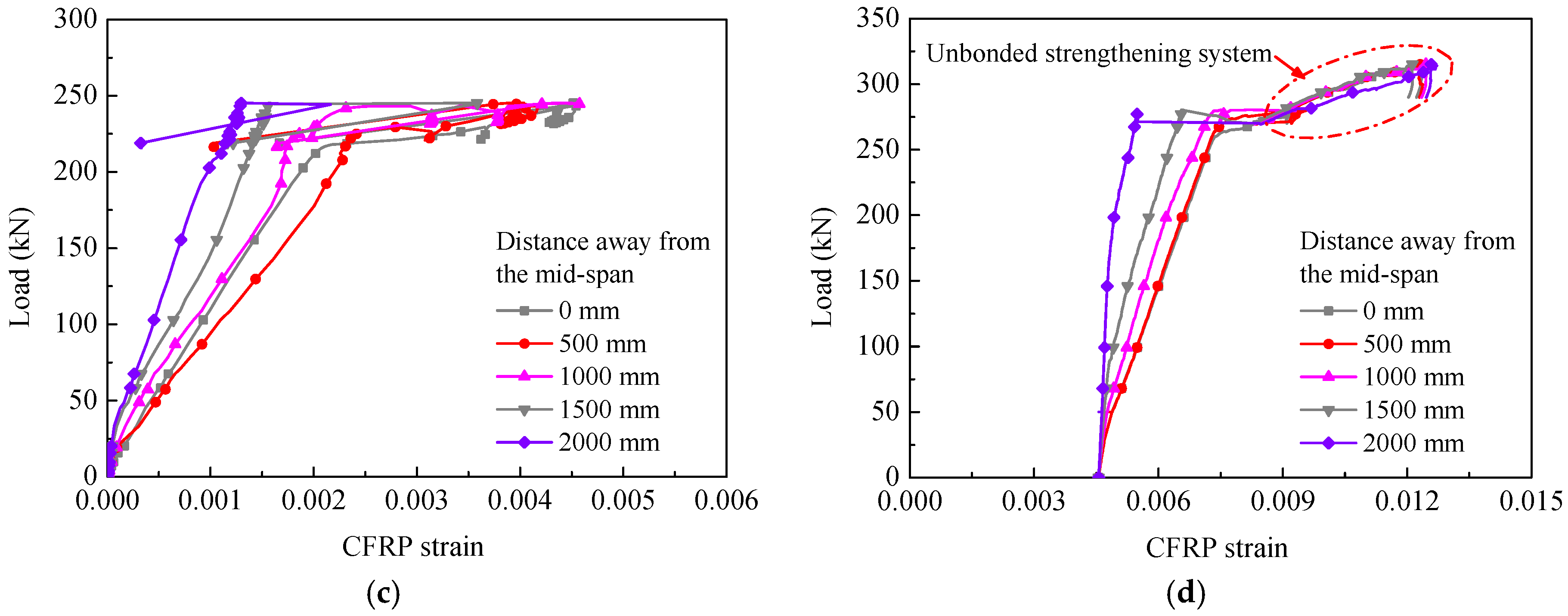
The CFRP utilization was considerably affected by the anchorage method and prestress. The adequate anchorage of the nonprestressed CFRP could increase the utilization at failure from less than 30% to 59% but had little effect on the utilization at the yielding load, which was only about 16%. However, the CFRP utilization at the yielding load and the failure state could be increased to more than 45% and 70%, respectively, by applying the prestress.
In the practical applications, a reliable anchorage method should be utilized. When the deflection and crack width need to be reduced, the prestressed CFRP strengthening technique is recommended. In addition, because this study only statically tested a limited large-scale RC beams, a systemic numerical studies should be conducted, and fatigue tests need to be carried out to investigate the fatigue behavior of RC beams strengthened with prestressed CFRP plates in the future.

 ,
, 


