
Properties of Lime-Cement Concrete Containing Various Amounts of Waste Tire Powder under Different Ground Moisture Conditions

 , and
, and
Abstract
: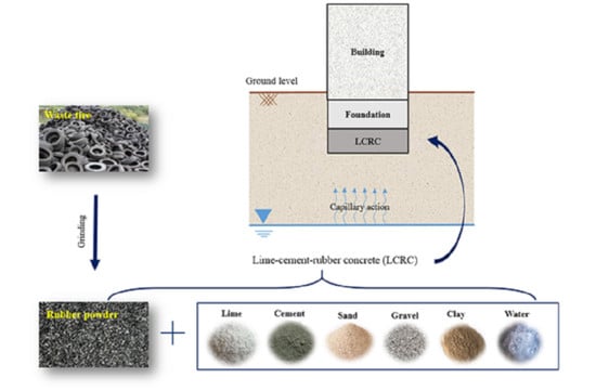
1. Introduction
2. Materials
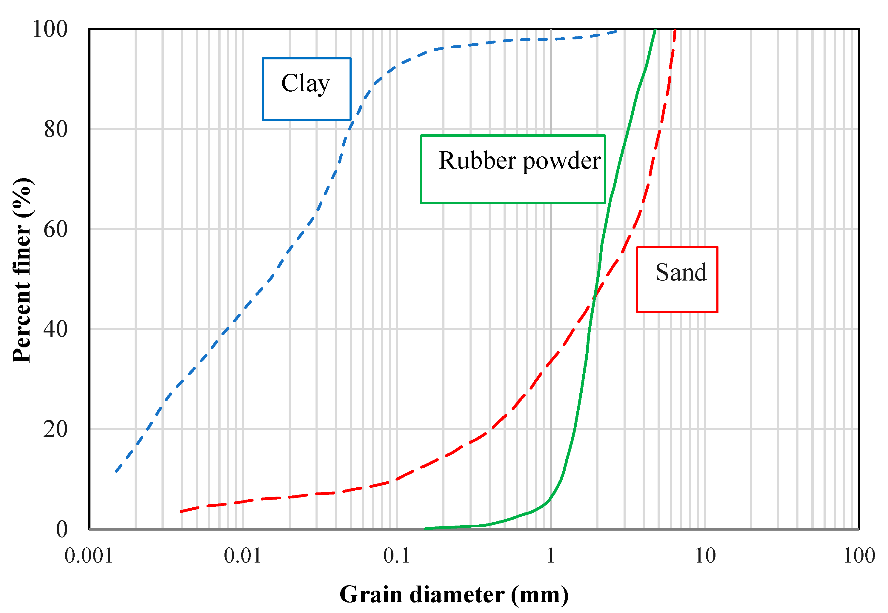
2.1. Soils and Aggregates
2.2. Binders
2.3. Water
3. Experimental Program and Methodology
3.1. Sample Preparation, Curing, and UCS Test
3.2. Workability
3.3. Water Absorption
3.4. Geotechnical Properties
4. Results and Discussion
4.1. Workability
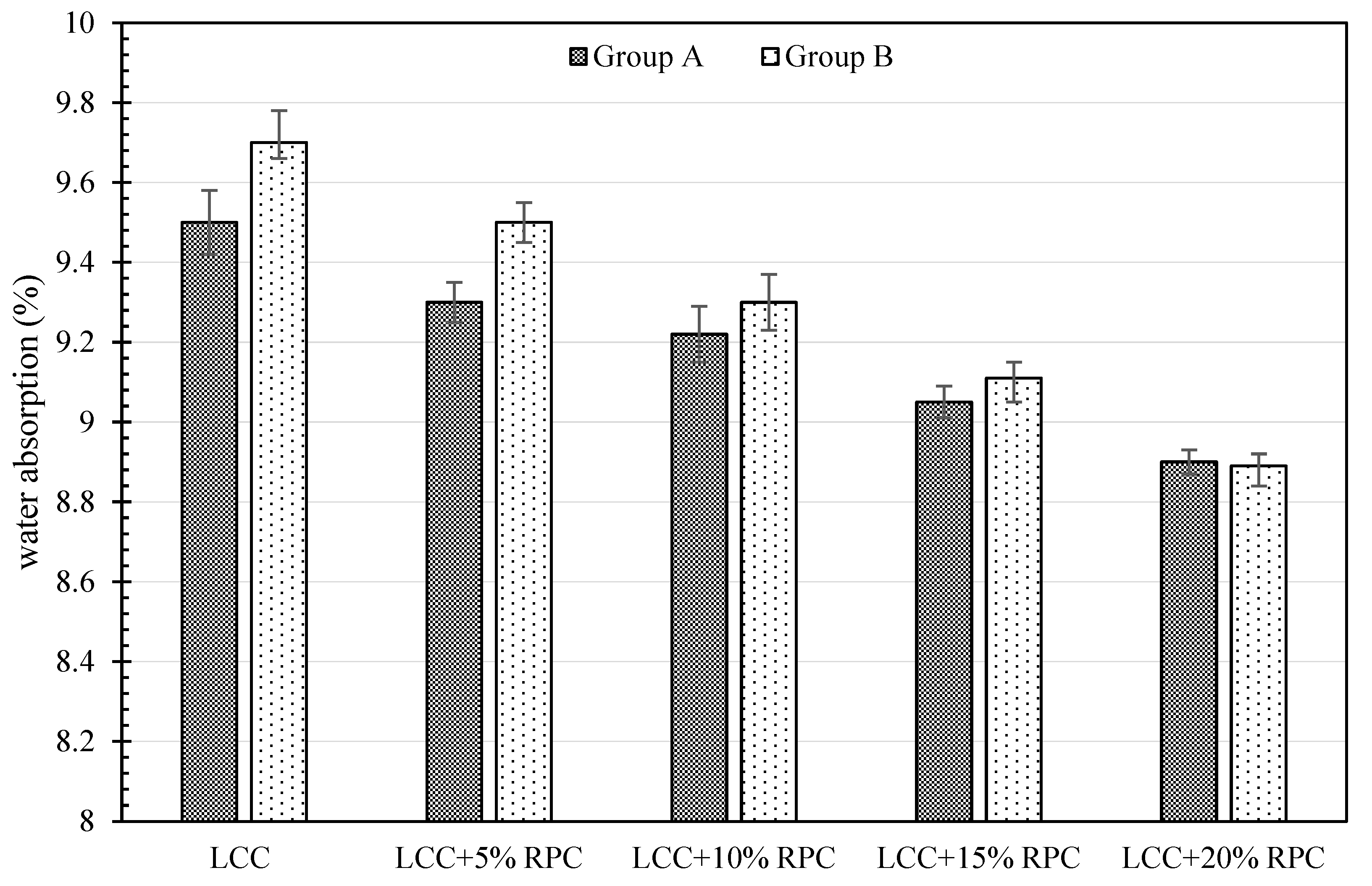
4.2. Water Absorption
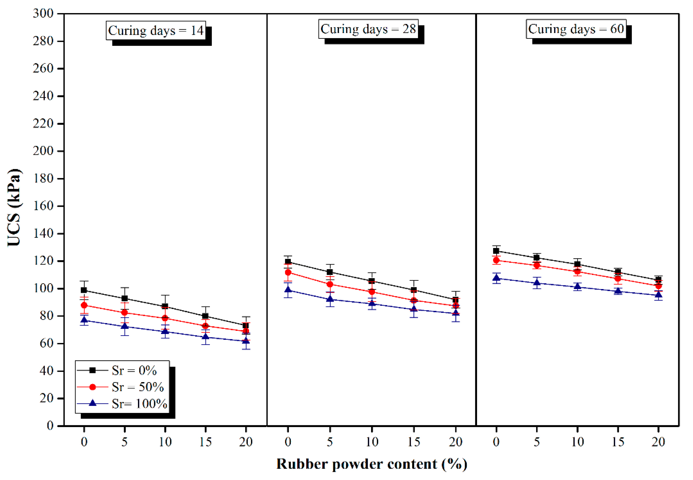
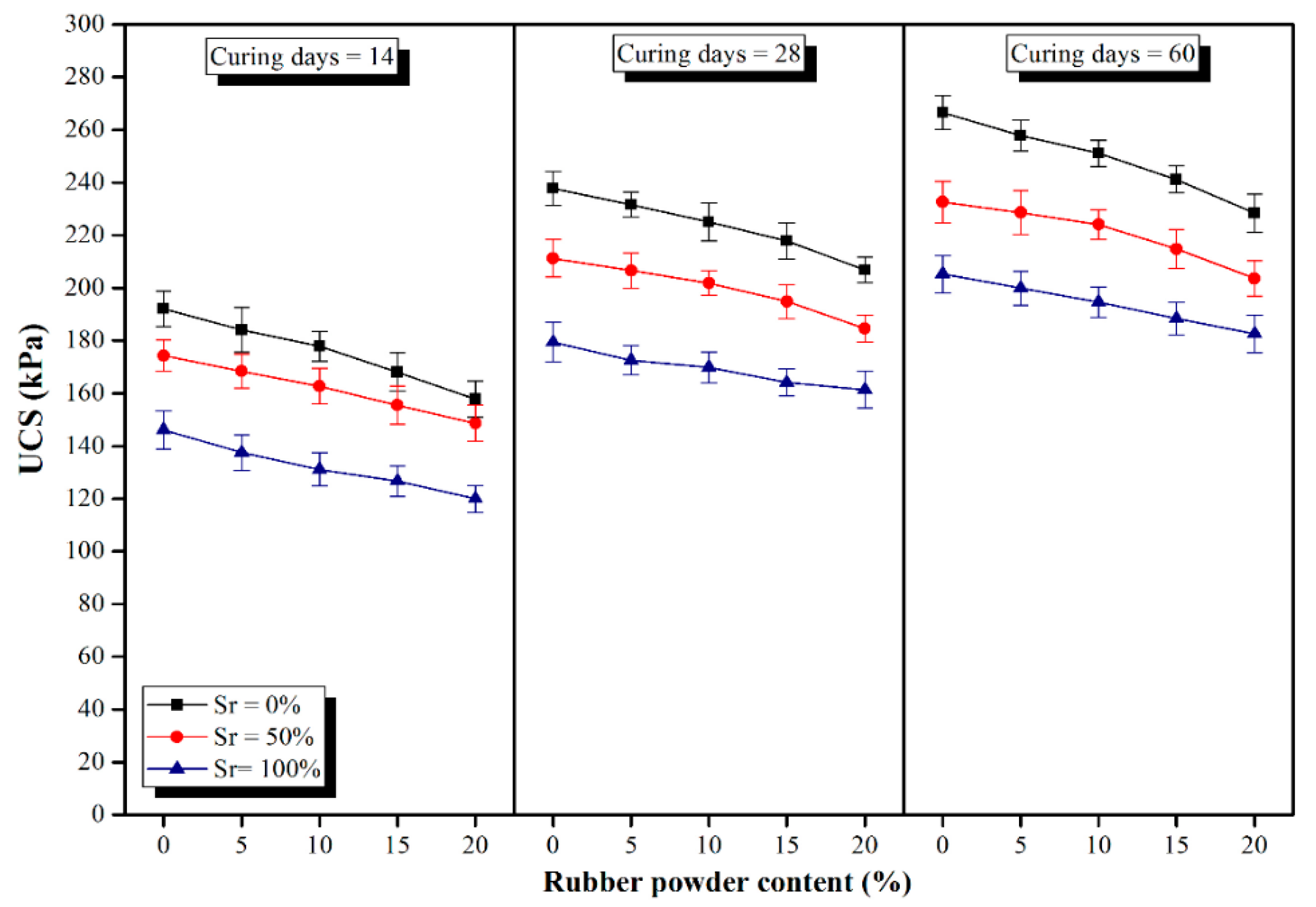
4.3. Compressive Strength
- (1)
- Rubber powder has lower strength values compared with its matrix around. Hence, when the concrete is subjected to external forces, the cracks first appear in the contact zone of the concrete matrix, and then they gradually initiate propagation until the concrete crumbles. Such discrepancy in the performance makes rubber particles act like voids in concrete [88,89,90,91,92,93,94,95].
- (2)
- (3)
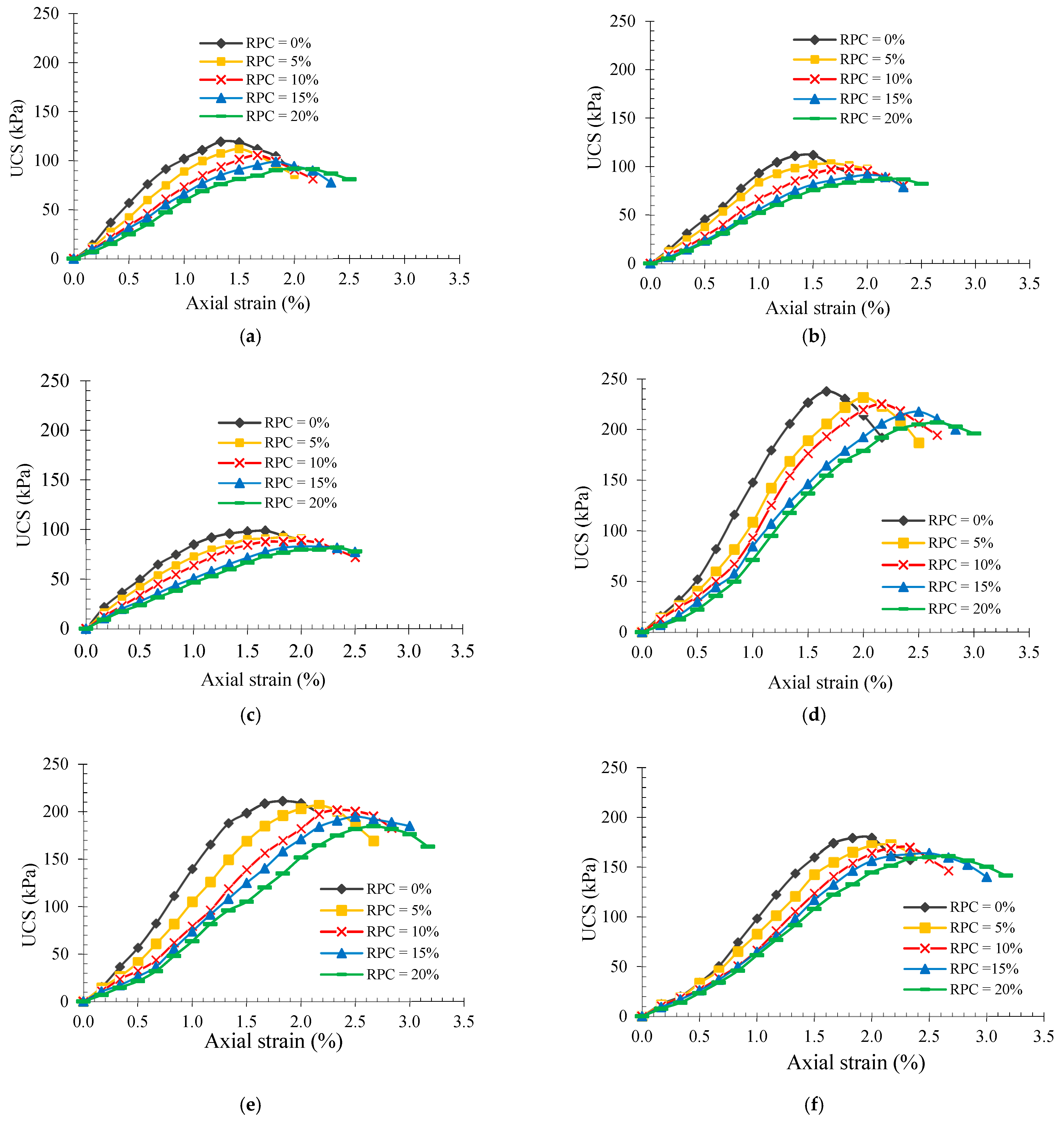
4.4. Stress–Strain Behaviour and Geotechnical Properties
5. Conclusions
- (1)
- Within a constant amount of binder, by increasing the lime content and decreasing the cement content, the UCS value decreased such that the UCS values of Group B samples were nearly two times those of Group A. Increasing the degree of saturation brought about a reduction in the UCS values at different curing times and various rubber powder contents. This could be attributed to the partial disintegration of the chemical bonds between lime and clayey soil. However, strength reduction due to the saturation increment was higher for samples from Group B compared with Group A; nevertheless, the ultimate UCS values of Group B samples, even in the condition of full saturation, were greatly higher than those obtained for the samples of Group A, implying their superb resistance in the presence of moisture.
- (2)
- LCC prepared with the mix design of Group B samples containing up to 10% rubber powder could be promisingly used in dry conditions and even underneath or close to the groundwater table with insignificant impact on the compressive strength and geotechnical properties because of rubber employment and/or exposure to moisture. Therefore, in some cities where vast amounts of waste tires are available, taking advantage of this waste material can not only provide reasonable resistance for LCC but can also alleviate the concerns and adverse environmental impacts associated with their disposal.
- (3)
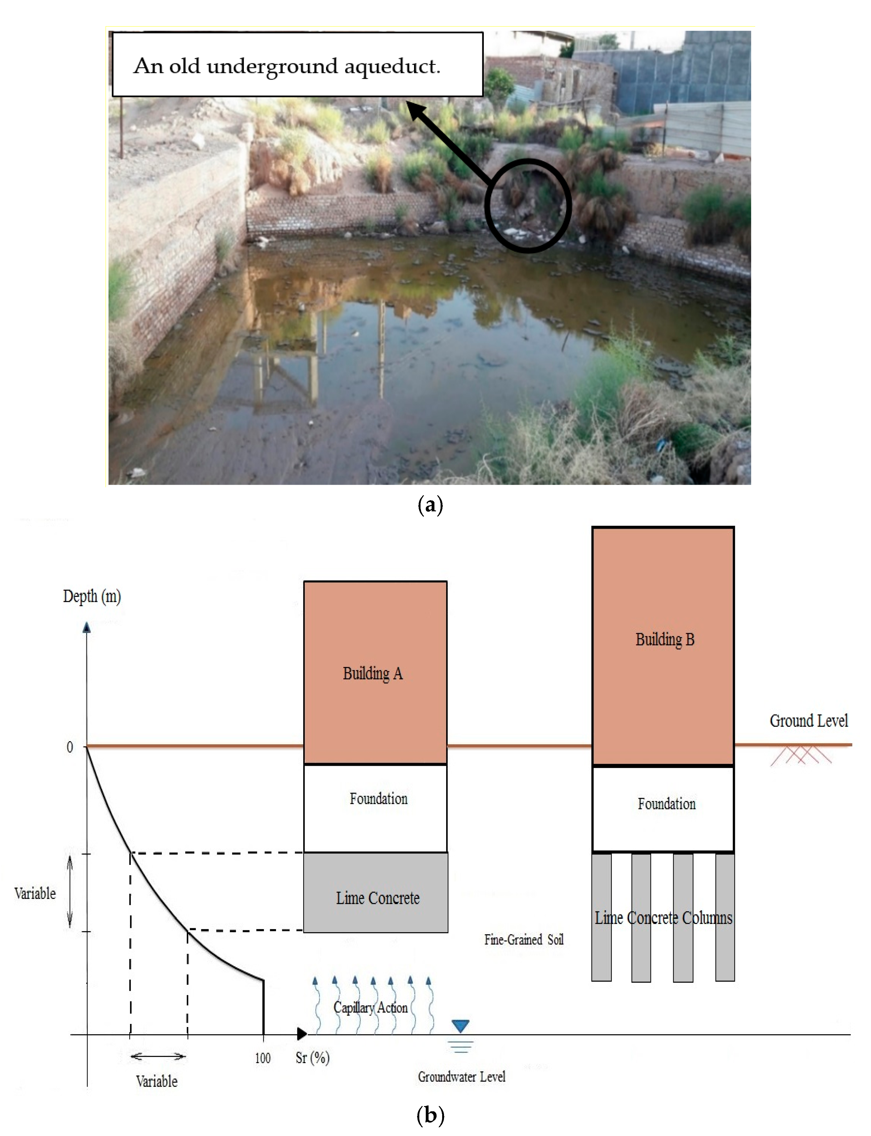
- However, it should be noted that LCC samples with the mix designs of Group A are considered suitable to be cast in a totally dry land where there is a long distance between the bottom of the concrete and groundwater level or where the moisture from any direction cannot reach the concrete due to the capillary suction, etc. It is reported that the capillary action can take place and moisturize the clayey soils even up to 25 m above the groundwater level. Therefore, in the construction sites where the type of soil is predominantly clayey soil (such as Kerman city in Iran), the use of LCC prepared with the mix designs of Group A is not considered rational. Nevertheless, it is obvious that the capillary suction is considerably limited in coarse-grained soils so that they could be used where the type of soil beneath the foundation is a coarse-grained soil with high drainage capacity.
- (4)
- The performance of LCC (containing rubber powder) against multiple wet–dry and freeze–thaw cycles has not been studied in this study; thus, it is recommended for future research to investigate the durability of LCC containing rubber powder against wet–dry and freeze–thaw cycles. Moreover, the results of ongoing research conducted by the authors indicated the superb performance of fly ash and wood ash when they are used as cement or lime replacements in lime-based concretes exposed to different ground moisture conditions. Thus, it is also recommended to investigate the use of these by-products in such lime-based concretes containing rubber powder.
Author Contributions
Funding
Institutional Review Board Statement
Informed Consent Statement
Data Availability Statement
Conflicts of Interest
References
- Pacheco-Torgal, F.; Ding, Y.; Jalali, S. Properties and durability of concrete containing polymeric wastes (tyre rubber and polyethylene terephthalate bottles): An overview. Constr. Build. Mater. 2012, 30, 714–724. [Google Scholar] [CrossRef] [Green Version]
- Yadav, J.S.; Tiwari, S.K. Effect of inclusion of crumb rubber on the unconfined compressive strength and wet-dry durability of cement stabilized clayey soil. J. Build. Mater. Struct. 2016, 3, 68–84. [Google Scholar]
- Romero-Flores, M.; Becerra-Lucatero, L.M.; Salmón-Folgueras, R.; Lopez-Salinas, J.L.; Bremer-Bremer, M.H.; Montesinos-Castellanos, A. Thermal performance of scrap tire blocks as roof insulator. Energy Build. 2017, 149, 384–390. [Google Scholar] [CrossRef]
- Siddique, R.; Naik, T.R. Properties of concrete containing scrap-tire rubber—An overview. Waste Manag. 2004, 24, 563–569. [Google Scholar] [CrossRef]
- Saberian, M.; Li, J.; Perera, S.T.A.M.; Zhou, A.; Roychand, R.; Ren, G. Large-scale direct shear testing of waste crushed rock reinforced with waste rubber as pavement base/subbase materials. Transp. Geotech. 2021, 28, 100546. [Google Scholar] [CrossRef]
- Saberian, M.; Li, J.; Boroujeni, M.; Law, D.; Li, C.-Q. Application of demolition wastes mixed with crushed glass and crumb rubber in pavement base/subbase. Resour. Conserv. Recycl. 2020, 156, 104722. [Google Scholar] [CrossRef]
- Li, J.; Saberian, M.; Nguyen, B.T. Effect of crumb rubber on the mechanical properties of crushed recycled pavement materials. J. Environ. Manag. 2018, 218, 291–299. [Google Scholar] [CrossRef]
- Khalilpasha, M.H.; Nik, A.S.; Omran, O.L.; Kimiaeifard, K.; Molla, M.A. Sustainable development using recyclable rubber in self-compacting concrete. In Proceedings of the Third International Conference on Construction in Developing Countries (Advancing Civil, Architectural and Construction Engineering & Management), Bangkok, Thailand, 4–6 July 2012; pp. 580–585. [Google Scholar]
- Pettinari, M.; Dondi, G.; Sangiorgi, C.; Petretto, F. The use of cryogenic crumb rubber in the cold recycling technique. In Airfield and Highway Pavement 2013: Sustainable and Efficient Pavements; American Society of Civil Engineers: Reston, VA, USA, 2013; pp. 1088–1099. [Google Scholar]
- Saberian, M.; Mehrinejad Khotbehsara, M.; Jahandari, S.; Vali, R.; Li, J.A. Experimental and phenomenological study of the effects of adding shredded tire chips on geotechnical properties of peat. Int. J. Geotech. Eng. 2018, 124, 347–356. [Google Scholar] [CrossRef]
- Liu, F.; Meng, L.-Y.; Ning, G.-F.; Li, L.-J. Fatigue performance of rubber-modified recycled aggregate concrete (RRAC) for pavement. Constr. Build. Mater. 2015, 95, 207–217. [Google Scholar] [CrossRef]
- Guo, Y.-C.; Zhang, J.-H.; Chen, G.-M.; Xie, Z.-H. Compressive behaviour of concrete structures incorporating recycled concrete aggregates, rubber crumb and reinforced with steel fibre, subjected to elevated temperatures. J. Clean. Prod. 2014, 72, 193–203. [Google Scholar] [CrossRef]
- Toghroli, A.; Mehrabi, P.; Shariati, M.; Trung, N.T.; Jahandari, S.; Rasekh, H. Evaluating the use of recycled concrete aggregate and pozzolanic additives in fiber-reinforced pervious concrete with industrial and recycled fibers. Constr. Build. Mater. 2020, 252, 118997. [Google Scholar] [CrossRef]
- Mehrabi, P.; Shariati, M.; Kabirifar, K.; Jarrah, M.; Rasekh, H.; Trung, N.T.; Shariati, A.; Jahandari, S. Effect of pumice powder and nano-clay on the strength and permeability of fiber-reinforced pervious concrete incorporating recycled concrete aggregate. Constr. Build. Mater. 2021, 287, 122652. [Google Scholar] [CrossRef]
- Kazemi, M.; Courard, L.; Hubert, J. Heat transfer measurement within green roof with incinerated municipal solid waste aggregates. Sustainability 2021, 13, 7115. [Google Scholar] [CrossRef]
- Rasekh, H.; Joshaghani, A.; Jahandari, S.; Aslani, F.; Ghodrat, M. Rheology and workability of SCC. In Self-Compacting Concrete: Materials, Properties and Applications; Elsevier: Amsterdam, The Netherlands, 2020; pp. 31–63. [Google Scholar]
- Lotfi-Omran, O.; Nikbin, I.; Manssouri, A.R.; Sadeghi-Nik, A.; Rabbanifar, S.; Fallahnejad, H. Propagation of ultrasonic waves in self-compacting -concrete and investigation of distribution of dynamic modulus of elasticity in concrete. J. Basic. Appl. Sci. Res. 2011, 1, 2319–2323. [Google Scholar]
- Nik, A.S.; Bahari, A.; Nik, A.S. Investigation of nano structural properties of cement-based materials. Am. J. Sci. Res 2011, 25, 104–111. [Google Scholar]
- Bahari, A.; Sadeghi-Nik, A.; Roodbari, M.; Sadeghi-Nik, A.; Mirshafiei, E. Experimental and theoretical studies of ordinary Portland cement composites contains nano LSCO perovskite with Fokker-Planck and chemical reaction equations. Constr. Build. Mater. 2018, 163, 247–255. [Google Scholar] [CrossRef]
- Farhangi, V.; Karakouzian, M. Effect of fiber reinforced polymer tubes filled with recycled materials and concrete on structural capacity of pile foundations. Appl. Sci. 2020, 10, 1554. [Google Scholar] [CrossRef] [Green Version]
- Mehrabi, P.; Honarbari, S.; Rafiei, S.; Jahandari, S.; Bidgoli, M.A. Seismic response prediction of FRC rectangular columns using intelligent fuzzy-based hybrid metaheuristic techniques. J. Ambient. Intell. Humaniz. Comput. 2021, 12, 10105–10123. [Google Scholar] [CrossRef]
- Feng, Y.; Mohammadi, M.; Wang, L.; Rashidi, M.; Mehrabi, P. Application of artificial intelligence to evaluate the fresh properties of self-consolidating concrete. Materials 2021, 14, 4885. [Google Scholar] [CrossRef]
- Saberian, M.; Jahandari, S.; Li, J.; Zivari, F. Effect of curing, capillary action, and groundwater level increment on geotechnical properties of lime concrete: Experimental and prediction studies. J. Rock Mech. Geotech. Eng. 2017, 9, 638–647. [Google Scholar] [CrossRef]
- Jahandari, S.; Saberian, M.; Tao, Z.; Mojtahedi, S.F.; Li, J.; Ghasemi, M.; Rezvani, S.S.; Li, W. Effects of saturation degrees, freezing-thawing, and curing on geotechnical properties of lime and lime-cement concretes. Cold Reg. Sci. Technol. 2019, 160, 242–251. [Google Scholar] [CrossRef]
- Sadeghian, F.; Haddad, A.; Jahandari, S.; Rasekh, H.; Ozbakkaloglu, T. Effects of electrokinetic phenomena on the load-bearing capacity of different steel and concrete piles: A small-scale experimental study. Can. Geotech. J. 2021, 58, 741–746. [Google Scholar] [CrossRef]
- Grist, E.; Paine, K.; Heath, A.; Norman, J.; Pinder, H. Structural and durability properties of hydraulic lime–pozzolan concretes. Cem. Concr. Compos. 2015, 62, 212–223. [Google Scholar] [CrossRef] [Green Version]
- Bartlett, S.; Farnsworth, C. Performance of lime cement stabilized soils for the I-15 reconstruction project: Salt Lake City Utah. Transp. Res. Rec. 2002, 1808, 58–66. [Google Scholar] [CrossRef]
- Rogers, C.; Boardman, D.; Papadimitriou, G. Stress path testing of realistically cured lime and lime/cement stabilized clay. J. Mater. Civ. Eng. 2006, 18, 259–266. [Google Scholar] [CrossRef]
- Malekpoor, M.R.; Toufigh, M.M. Laboratory study of soft soil improvement using lime mortar-(well graded) soil columns. Geotech. Test. J. 2010, 33, 225–235. [Google Scholar]
- Jahandari, S.; Li, J.; Saberian, M.; Shahsavarigoughari, M. Experimental study of the effects of geogrids on elasticity modulus, brittleness, strength, and stress-strain behavior of lime stabilized kaolinitic clay. GeoResJ 2017, 13, 49–58. [Google Scholar] [CrossRef]
- Jahandari, S.; Saberian, M.; Zivari, F.; Li, J.; Ghasemi, M.; Vali, R. Experimental study of the effects of curing time on geotechnical properties of stabilized clay with lime and geogrid. Int. J. Geotech. Eng. 2019, 13, 172–183. [Google Scholar] [CrossRef]
- Toohey, N.; Mooney, M.; Bearce, R. Stress-strain-strength behavior of lime-stabilized soils during accelerated curing. J. Mater. Civ. Eng. 2013, 25, 1880–1886. [Google Scholar] [CrossRef] [Green Version]
- Firoozfar, A.; Khosroshiri, N. Kerman clay improvement by lime and bentonite to be used as materials of landfill liner. Geotech. Geol. Eng. 2017, 35, 559–571. [Google Scholar] [CrossRef]
- Jahandari, S.; Toufigh, M.M.; Li, J.; Saberian, M. Laboratory study of the effect of degrees of saturation on lime concrete resistance due to the groundwater level increment. Geotech. Geol. Eng. 2018, 36, 413–424. [Google Scholar] [CrossRef]
- ASTM C618; Standard Specification for Coal Fly Ash and Raw or Calcined Natural Pozzolan for Use in Concrete. ASTM International: West Conshohocken, PA, USA, 2012.
- Sirivitmaitrie, C.; Puppala, A.J.; Saride, S.; Hoyos, L. Combined lime–cement stabilization for longer life of low-volume roads. Transp. Res. Rec. 2011, 2204, 140–147. [Google Scholar] [CrossRef]
- ASTM 2487-11; Standard Practice for Classification of Soils for Engineering Purposes (Unified Soil Classification System). ASTM International: West Conshohocken, PA, USA, 2011.
- ASTM D422-63; Standard Test Method for Particle-Analysis of Soils. ASTM International: West Conshohocken, PA, USA, 2002.
- ASTM D424–54; Standard Method of Test for Plastic Limit. ASTM International: West Conshohocken, PA, USA, 1982.
- ASTM D423–66; Standard Method of Test for Liquid Limit of Soils. ASTM International: West Conshohocken, PA, USA, 1972.
- Das, B.M. Advanced Soil Mechanics, 3rd ed.; Taylor & Francis: New York, NY, USA, 2008. [Google Scholar]
- AASHTO T180; Standard Method of Test for Moisture Density Relations of Soils Using a 4.54 kg (10-lb) Rammer and a 457 mm (18-in.) Drop. American Association of State Highway and Transportation Officials: Washington, DC, USA, 2010.
- ASTM D854-10; Standard Test Methods for Specific Gravity of Soil Solids by Water Pycnometer. ASTM International: West Conshohocken, PA, USA, 2010.
- ASTM C977-18; Standard Specification for Quicklime and Hydrated Lime for Soil Stabilization. ASTM International: West Conshohocken, PA, USA, 2018.
- Athanasopoulou, A. Addition of lime and fly ash to improve highway subgrade soils. J. Mater. Civ. Eng. 2014, 26, 773–775. [Google Scholar] [CrossRef]
- Miraki, H.; Shariatmadari, N.; Ghadir, P.; Jahandari, S.; Tao, Z.; Siddique, R. Clayey soil stabilization using alkali-activated volcanic ash and slag. J. Rock Mech. Geotech. Eng. 2021; in press. [Google Scholar] [CrossRef]
- Ghadir, P.; Ranjbar, N. Clayey soil stabilization using geopolymer and Portland cement. Constr. Build. Mater. 2018, 188, 361–371. [Google Scholar] [CrossRef]
- Jahandari, S.; Tao, Z.; Alim, M.A. Effects of different integral hydrophobic admixtures on the properties of concrete. In Proceedings of the 30th Biennial National Conference of the Concrete Institute of Australia, Perth, Australia, 5–8 September 2021. [Google Scholar]
- Jahandari, S.; Tao, Z.; Saberian, M.; Shariati, M.; Li, J.; Abolhasani, M.; Kazemi, M.; Rahmani, A.; Rashidi, M. Geotechnical properties of lime-geogrid improved clayey subgrade under various moisture conditions. Road Mater. Pavement Des. 2021. [Google Scholar] [CrossRef]
- Parsajoo, M.; Armaghani, D.J.; Mohammed, A.S.; Khari, M.; Jahandari, S. Tensile strength prediction of rock material using non-destructive tests: A comparative intelligent study. Transp. Geotech. 2021, 31, 100652. [Google Scholar] [CrossRef]
- Mohammadi, M.; Kafi, M.A.; Kheyroddin, A.; Ronagh, H. Performance of innovative composite buckling-restrained fuse for concentrically braced frames under cyclic loading. Steel Compos. Struct. Int. J. 2020, 36, 163–177. [Google Scholar]
- Jahandari, S.; Mohammadi, M.; Rahmani, A.; Abolhasani, M.; Miraki, H.; Mohammadifar, L.; Kazemi, M.; Saberian, M.; Rashidi, M. Mechanical properties of recycled aggregate concretes containing silica fume and steel fibres. Materials 2021, 14, 7065. [Google Scholar] [CrossRef]
- Sadeghian, F.; Jahandari, S.; Haddad, A.; Rasekh, H.; Li, J. Effects of variations of voltage and pH value on the shear strength of soil and durability of different electrodes and piles during electrokinetic phenomenon. J. Rock Mech. Geotech. Eng. 2021; in press. [Google Scholar] [CrossRef]
- Mehdizadeh, B.; Jahandari, S.; Vessalas, K.; Miraki, H.; Rasekh, H.; Samali, B. Fresh, mechanical, and durability properties of self-compacting mortar incorporating alumina nanoparticles and rice husk ash. Materials 2021, 14, 6778. [Google Scholar] [CrossRef]
- Mohammadi, M.; Kafi, M.A.; Kheyroddin, A.; Ronagh, H.R. Experimental and numerical investigation of an innovative buckling-restrained fuse under cyclic loading. Structures 2019, 22, 86–199. [Google Scholar] [CrossRef]
- Afshar, A.; Jahandari, S.; Rasekh, H.; Shariati, M.; Afshar, A.; Shokrgozar, A. Corrosion resistance evaluation of rebars with various primers and coatings in concrete modified with different additives. Constr. Build. Mater. 2020, 262, 120034. [Google Scholar] [CrossRef]
- Kazemi, M.; Hajforoush, M.; Talebi, P.K.; Daneshfar, M.; Shokrgozar, A.; Jahandari, S.; Saberian, M.; Li, J. In-situ strength estimation of polypropylene fibre reinforced recycled aggregate concrete using Schmidt rebound hammer and point load test. J. Sustain. Cem.-Based Mater. 2020, 9, 289–306. [Google Scholar] [CrossRef]
- Xu, J.; Wu, Z.; Chen, H.; Shao, L.; Zhou, X.; Wang, S. Study on strength behavior of basalt fiber-reinforced loess by digital image technology (DIT) and scanning electron microscope (SEM). Arab. J. Sci. Eng. 2021, 46, 11319–11338. [Google Scholar] [CrossRef]
- Xu, J.; Wu, Z.; Chen, H.; Shao, L.; Zhou, X.; Wang, S. Triaxial shear behavior of basalt fiber-reinforced loess based on digital image technology. KSCE J. Civ. Eng. 2021, 25, 3714–3726. [Google Scholar] [CrossRef]
- Huang, H.; Huang, M.; Zhang, W.; Yang, S. Experimental study of predamaged columns strengthened by HPFL and BSP under combined load cases. Struct. Infrastruct. Eng. 2021, 17, 1210–1227. [Google Scholar] [CrossRef]
- Chen, F.-X.; Zhong, Y.-C.; Gao, X.-Y.; Jin, Z.-Q.; Wang, E.-D.; Zhu, F.-P.; Shao, X.-X.; He, X.-Y. Non-uniform model of relationship between surface strain and rust expansion force of reinforced concrete. Sci. Rep. 2021, 11, 8741. [Google Scholar] [CrossRef]
- Zhang, H.; Liu, Y.; Deng, Y. Temperature gradient modeling of a steel box-girder suspension bridge using Copulas probabilistic method and field monitoring. Adv. Struct. Eng. 2021, 24, 947–961. [Google Scholar] [CrossRef]
- Liu, W.; Guo, Z.; Wang, C.; Niu, S. Physico-mechanical and microstructure properties of cemented coal Gangue-Fly ash backfill: Effects of curing temperature. Constr. Build. Mater. 2021, 299, 124011. [Google Scholar] [CrossRef]
- Xu, D.; Liu, Q.; Qin, Y.; Chen, B. Analytical approach for crack identification of glass fiber reinforced polymer–sea sand concrete composite structures based on strain dissipations. Struct. Health Monit. 2020, 1475921720974290. [Google Scholar] [CrossRef]
- Zhang, W.; Tang, Z. Numerical modeling of response of CFRP–concrete interfaces subjected to fatigue loading. J. Compos. Constr. 2021, 25, 04021043. [Google Scholar] [CrossRef]
- Zhang, W.; Tang, Z.; Yang, Y.; Wei, J.; Stanislav, P. Mixed-mode debonding behavior between CFRP plates and concrete under fatigue loading. J. Struct. Eng. 2021, 147, 04021055. [Google Scholar] [CrossRef]
- Rezania, M.; Moradnezhad, H.; Panahandeh, M.; Kami, M.J.R.; Rahmani, A.; Hosseini, B.V. Effects of diethanolamine (DEA) and glass fibre reinforced polymer (GFRP) on setting time and mechanical properties of shotcrete. J. Build. Eng. 2020, 31, 101343. [Google Scholar] [CrossRef]
- Darvishi, A.; Vosoughifar, H.; Saeidijam, S.; Torabi, M.; Rahmani, A. An experimental and prediction study on the compaction and swell–expansion behavior of bentonite clay containing various percentages of two different synthetic fibers. Innov. Infrastruct. Solut. 2020, 5, 31. [Google Scholar] [CrossRef]
- Hanaei, F.; Sarmadi, M.S.; Rezaee, M.; Rahmani, A. Experimental investigation of the effects of gas oil and benzene on the geotechnical properties of sandy soils. Innov. Infrastruct. Solut. 2021, 6, 61. [Google Scholar] [CrossRef]
- ASTM 5102; Standard Test Method for Unconfined Compressive Strength of Compacted Soil-Lime Mixtures. ASTM International: West Conshohocken, PA, USA, 2009.
- Ameri, M.; Kalantari, B.; Jahandari, S. Laboratory study of determination of optimum amount of water and clay in mortar made with lime and fly ash. In Proceedings of the International Conference on Research in Science and Technology, Kualalumpur, Malaysia, 14 December 2015. [Google Scholar]
- ASTM C270; Standard Specification for Mortar for Unit Masonry. ASTM International: West Conshohocken, PA, USA, 2007.
- ASTM C642; Standard Test Method for Density, Absorption, and Voids in Hardened Concrete. ASTM International: West Conshohocken, PA, USA, 2013.
- Jahandari, S.; Mojtahedi, S.F.; Zivari, F.; Jafari, M.; Mahmoudi, M.R.; Shokrgozar, A.; Kharazmi, S.; Vosough Hosseini, B.; Rezvani, S.; Jalalifar, H. The impact of long-term curing period on the mechanical features of lime-geogrid treated soils. Geomech. Geoengin. 2020. [Google Scholar] [CrossRef]
- Mirzababaei, M.; Miraftab, M.; Mohamed, M.; McMahon, P. Unconfined compression strength of reinforced clays with carpet waste fibers. J. Geotech. Geoenviron. Eng. 2013, 139, 483–493. [Google Scholar] [CrossRef]
- Cong, M.; Longzhu, C.; Bing, C. Analysis of strength development in soft clay stabilized with cement-based stabilizer. Constr. Build. Mater. 2014, 71, 354–362. [Google Scholar] [CrossRef]
- Karaca, Z.; Onargan, T. A new approach to stone deformation: Stone deformability index. Proc. Inst. Civ. Eng.-Constr. Mater. 2012, 165, 189–195. [Google Scholar] [CrossRef]
- Park, S.-S. Unconfined compressive strength and ductility of fiber-reinforced cemented sand. Constr. Build. Mater. 2011, 25, 1134–1138. [Google Scholar] [CrossRef]
- Duncan, J.M.; Bursey, A. Soil modulus correlations. In Foundation Engineering in the Face of Uncertainty: Honoring Fred H. Kulhawy; American Society of Civil Engineers: Reston, VA, USA, 2013; pp. 321–336. [Google Scholar]
- Ghourchian, S.; Wyrzykowski, M.; Lura, P. The bleeding test: A simple method for obtaining the permeability and bulk modulus of fresh concrete. Cem. Concr. Res. 2016, 89, 249–256. [Google Scholar] [CrossRef]
- Han, Z.; Vanapalli, S.K. Relationship between resilient modulus and suction for compacted subgrade soils. Eng. Geol. 2016, 211, 85–97. [Google Scholar] [CrossRef]
- Sadrossadat, E.; Heidaripanah, A.; Osouli, S. Prediction of the resilient modulus of flexible pavement subgrade soils using adaptive neuro-fuzzy inference systems. Constr. Build. Mater. 2016, 123, 235–247. [Google Scholar] [CrossRef]
- Thompson, M.R. The Split-Tensile Strength of Lime-Stabilized Soils; University of Illinois: Champaign, IL, USA, 1966. [Google Scholar]
- Carlton, B.D.; Pestana, J.M. A unified model for estimating the in-situ small strain shear modulus of clays, silts, sands, and gravels. Soil Dyn. Earthq. Eng. 2016, 88, 345–355. [Google Scholar] [CrossRef] [Green Version]
- Selvadurai, A.; Katebi, A. Mindlin’s problem for an incompressible elastic half-space with an exponential variation in the linear elastic shear modulus. Int. J. Eng. Sci. 2013, 65, 9–21. [Google Scholar] [CrossRef]
- Lollini, F.; Redaelli, E.; Bertolini, L. Effects of portland cement replacement with limestone on the properties of hardened concrete. Cem. Concr. Compos. 2014, 46, 32–40. [Google Scholar] [CrossRef]
- Li, L.-J.; Tu, G.-R.; Lan, C.; Liu, F. Mechanical characterization of waste-rubber-modified recycled-aggregate concrete. J. Clean. Prod. 2016, 124, 325–338. [Google Scholar] [CrossRef]
- Benazzouk, A.; Douzane, O.; Mezreb, K.; Quéneudec, M. Physico-mechanical properties of aerated cement composites containing shredded rubber waste. Cem. Concr. Compos. 2006, 28, 650–657. [Google Scholar] [CrossRef]
- Bignozzi, M.; Sandrolini, F. Tyre rubber waste recycling in self-compacting concrete. Cem. Concr. Res. 2006, 36, 735–739. [Google Scholar] [CrossRef]
- Eldin, N.N.; Senouci, A.B. Measurement and prediction of the strength of rubberized concrete. Cem. Concr. Compos. 1994, 16, 287–298. [Google Scholar] [CrossRef]
- Güneyisi, E.; Gesoğlu, M.; Özturan, T. Properties of rubberized concretes containing silica fume. Cem. Concr. Res. 2004, 34, 2309–2317. [Google Scholar] [CrossRef]
- Khatib, Z.K.; Bayomy, F.M. Rubberized Portland cement concrete. J. Mater. Civ. Eng. 1999, 11, 206–213. [Google Scholar] [CrossRef]
- Lee, B.; Burnett, L.; Miller, T.; Cuneo, J. Tyre rubber/cement matrix composites. J. Mater. Sci. Lett. 1993, 12, 967–968. [Google Scholar] [CrossRef]
- Papakonstantinou, C.G.; Tobolski, M.J. Use of waste tire steel beads in Portland cement concrete. Cem. Concr. Res. 2006, 36, 1686–1691. [Google Scholar] [CrossRef]
- Topçu, I.B.; Avcular, N. Collision behaviours of rubberized concrete. Cem. Concr. Res. 1997, 27, 1893–1898. [Google Scholar] [CrossRef]
- Aiello, M.A.; Leuzzi, F. Waste tyre rubberized concrete: Properties at fresh and hardened state. Waste Manag. 2010, 30, 1696–1704. [Google Scholar] [CrossRef]
- Batayneh, M.K.; Marie, I.; Asi, I. Promoting the use of crumb rubber concrete in developing countries. Waste Manag. 2008, 28, 2171–2176. [Google Scholar] [CrossRef] [PubMed]
- Hernández-Olivares, F.; Barluenga, G. Fire performance of recycled rubber-filled high-strength concrete. Cem. Concr. Res. 2004, 34, 109–117. [Google Scholar] [CrossRef]
- Li, G.; Stubblefield, M.A.; Garrick, G.; Eggers, J.; Abadie, C.; Huang, B. Development of waste tire modified concrete. Cem. Concr. Res. 2004, 34, 2283–2289. [Google Scholar] [CrossRef]
- Segre, N.; Joekes, I. Use of tire rubber particles as addition to cement paste. Cem. Concr. Res. 2000, 30, 1421–1425. [Google Scholar] [CrossRef]
- Larrahondo, J.; Zhao, Q.; Burns, S.; Elliott, W. Effects of ferric oxyhydroxide coatings on sand shear response: A laboratory approach to chemical weathering. In Characterization and Behavior of Interfaces; IOS Press: Amsterdam, The Netherlands, 2010; pp. 63–70. [Google Scholar]
- Anggraini, V.; Asadi, A.; Farzadnia, N.; Jahangirian, H.; Huat, B.B. Reinforcement benefits of nanomodified coir fiber in lime-treated marine clay. J. Mater. Civ. Eng. 2016, 28, 06016005. [Google Scholar] [CrossRef]


| Characteristics | Results | Used References |
|---|---|---|
| Coarse-grained soil type (sand) | SW-SM | [37] |
| Effective size (D10) | 0.10 | [38] |
| Uniformity coefficient (Cu) | 34 | [38] |
| Coefficient of curvature (Cc) | 1.88 | [38] |
| Plastic limit (PL) | 22% | [39] |
| Liquid limit (LL) | 27% | [40] |
| Plasticity index (PI) | 5% | [41] |
| Fine-grained soil type (clay) | CL | [37] |
| Mineral of CL | Kaolinite | [41] |
| Activity degree (A) of CL | 0.47 | [41] |
| D10 of CL | 0.0015 | [38] |
| Cu of CL | 18 | [38] |
| Cc of CL | 0.40 | [38] |
| PL of CL | 23% | [39] |
| LL of CL | 34% | [40] |
| PI of CL | 11% | [41] |
| Optimum water content (ωopt) of CL | 15% | [42] |
| Maximum dry density (γd) of CL | 18.75 kN/m3 | [42] |
| Specific gravity (Gs) of CL | 2.47 | [43] |
| Component Oxides | Composition of Clay (%) | Composition of Lime (%) | Composition of Cement (%) |
|---|---|---|---|
| CaO | 13.20 | 73.70 | 63.41 |
| SiO2 | 41.75 | 1.15 | 21.63 |
| Al2O3 | 15.15 | 0.11 | 4.21 |
| Fe2O3 | 5.21 | 0.27 | 3.12 |
| MgO | 5.15 | 1.60 | 2.81 |
| SO3 | 3.48 | 0.02 | 2.61 |
| NaCl | 0.08 | 0.01 | - |
| Loss on ignition | 12.58 | 23.15 | 0.81 |
| Variables and Constants | Values |
|---|---|
| Cement (%) + Lime (%) | 2 + 5; 4 + 3 |
| Rubber powder content (by dry weight of the coarse-grained soil (%)) | 0, 5, 10, 15, 20 |
| Saturation degrees (%) | 0, 50, 100 |
| Curing times (days) | 14, 28, 60 |
| Clay (by the total dry weight of the coarse-grained soil and rubber powder (%)) | 23 |
| Water (by total dry weight of all the materials (%)) | 24.04 |
| Curing Period (Day) | Sr (%) | RPC (%) | UCS (kPa) | εf (%) | Es (MPa) | ID | K (MPa) | MR (MPa) | G (MPa) |
|---|---|---|---|---|---|---|---|---|---|
| 14 | 0 | 0 | 98.66 | 1.83 | 5.39 | - | 4.49 | 81.03 | 2.07 |
| 0 | 5 | 92.78 | 2.00 | 4.64 | 1.09 | 3.87 | 80.30 | 1.78 | |
| 0 | 10 | 86.93 | 2.16 | 4.02 | 1.18 | 3.35 | 79.58 | 1.55 | |
| 0 | 15 | 79.93 | 2.33 | 3.43 | 1.27 | 2.86 | 78.71 | 1.32 | |
| 0 | 20 | 73.17 | 2.50 | 2.93 | 1.37 | 2.44 | 77.87 | 1.13 | |
| 50 | 0 | 87.91 | 2.00 | 4.40 | - | 3.66 | 79.70 | 1.69 | |
| 50 | 5 | 82.44 | 2.16 | 3.82 | 1.08 | 3.18 | 79.02 | 1.47 | |
| 50 | 10 | 78.44 | 2.33 | 3.37 | 1.17 | 2.81 | 78.53 | 1.29 | |
| 50 | 15 | 72.82 | 2.50 | 2.91 | 1.25 | 2.43 | 77.83 | 1.12 | |
| 50 | 20 | 68.93 | 2.67 | 2.58 | 1.34 | 2.15 | 77.35 | 0.99 | |
| 100 | 0 | 76.82 | 2.17 | 3.54 | - | 2.95 | 78.33 | 1.36 | |
| 100 | 5 | 72.32 | 2.33 | 3.10 | 1.08 | 2.59 | 77.77 | 1.19 | |
| 100 | 10 | 68.69 | 2.50 | 2.75 | 1.15 | 2.29 | 77.32 | 1.06 | |
| 100 | 15 | 64.67 | 2.67 | 2.42 | 1.23 | 2.02 | 76.82 | 0.93 | |
| 100 | 20 | 61.69 | 2.83 | 2.18 | 1.31 | 1.82 | 76.45 | 0.84 | |
| 28 | 0 | 0 | 119.41 | 1.33 | 11.48 | - | 9.57 | 83.61 | 4.42 |
| 0 | 5 | 111.92 | 1.50 | 9.17 | 1.13 | 7.64 | 82.68 | 3.53 | |
| 0 | 10 | 105.44 | 1.67 | 6.76 | 1.25 | 5.63 | 81.87 | 2.60 | |
| 0 | 15 | 98.93 | 1.83 | 6.60 | 1.38 | 5.50 | 81.07 | 2.54 | |
| 0 | 20 | 91.92 | 2.00 | 5.82 | 1.50 | 4.85 | 80.20 | 2.24 | |
| 50 | 0 | 111.77 | 1.50 | 9.25 | - | 7.70 | 82.66 | 3.56 | |
| 50 | 5 | 103.06 | 1.67 | 7.98 | 1.11 | 6.65 | 81.58 | 3.07 | |
| 50 | 10 | 97.67 | 1.83 | 6.42 | 1.22 | 5.35 | 80.91 | 2.47 | |
| 50 | 15 | 91.42 | 2.00 | 5.52 | 1.33 | 4.60 | 80.14 | 2.12 | |
| 50 | 20 | 87.44 | 2.17 | 5.14 | 1.44 | 4.28 | 79.64 | 1.98 | |
| 100 | 0 | 98.82 | 1.66 | 9.88 | - | 8.24 | 81.05 | 3.80 | |
| 100 | 5 | 92.18 | 1.83 | 8.38 | 1.10 | 6.98 | 80.23 | 3.22 | |
| 100 | 10 | 88.94 | 2.00 | 6.66 | 1.20 | 5.55 | 79.83 | 2.56 | |
| 100 | 15 | 82.82 | 2.17 | 5.17 | 1.31 | 4.31 | 79.32 | 1.99 | |
| 100 | 20 | 81.93 | 2.33 | 4.88 | 1.41 | 4.06 | 78.96 | 1.88 | |
| 60 | 0 | 0 | 127.41 | 1.16 | 10.98 | - | 9.15 | 84.60 | 4.22 |
| 0 | 5 | 122.40 | 1.33 | 9.20 | 1.15 | 7.67 | 83.98 | 3.54 | |
| 0 | 10 | 117.66 | 1.50 | 7.84 | 1.29 | 6.54 | 83.39 | 3.02 | |
| 0 | 15 | 111.91 | 1.67 | 6.71 | 1.44 | 5.59 | 82.68 | 2.58 | |
| 0 | 20 | 106.15 | 1.83 | 5.80 | 1.58 | 4.83 | 81.96 | 2.23 | |
| 50 | 0 | 120.54 | 1.33 | 9.06 | - | 7.55 | 83.75 | 3.49 | |
| 50 | 5 | 116.89 | 1.50 | 7.79 | 1.13 | 6.49 | 83.29 | 3.00 | |
| 50 | 10 | 112.41 | 1.67 | 6.74 | 1.25 | 5.62 | 82.74 | 2.59 | |
| 50 | 15 | 107.16 | 1.83 | 5.86 | 1.38 | 4.88 | 82.09 | 2.25 | |
| 50 | 20 | 101.91 | 2.00 | 5.10 | 1.50 | 4.25 | 81.44 | 1.96 | |
| 100 | 0 | 107.55 | 1.50 | 7.17 | - | 5.98 | 82.14 | 2.76 | |
| 100 | 5 | 103.92 | 1.67 | 6.23 | 1.11 | 5.19 | 81.69 | 2.40 | |
| 100 | 10 | 101.17 | 1.83 | 5.53 | 1.22 | 4.61 | 81.35 | 2.13 | |
| 100 | 15 | 97.92 | 2.00 | 4.90 | 1.33 | 4.08 | 80.94 | 1.88 | |
| 100 | 20 | 95.17 | 2.17 | 4.39 | 1.44 | 3.66 | 80.60 | 1.69 |
| Curing Period (Day) | Sr (%) | RPC (%) | UCS (kPa) | εf (%) | Es (MPa) | ID | K (MPa) | MR (MPa) | G (MPa) |
|---|---|---|---|---|---|---|---|---|---|
| 14 | 0 | 0 | 192.15 | 2.00 | 9.61 | - | 8.01 | 92.63 | 3.70 |
| 0 | 5 | 184.14 | 2.16 | 8.53 | 1.08 | 7.10 | 91.63 | 3.28 | |
| 0 | 10 | 177.87 | 2.33 | 7.63 | 1.17 | 6.36 | 90.86 | 2.94 | |
| 0 | 15 | 168.10 | 2.50 | 6.72 | 1.25 | 5.60 | 89.64 | 2.59 | |
| 0 | 20 | 157.78 | 2.67 | 5.91 | 1.34 | 4.92 | 88.36 | 2.27 | |
| 50 | 0 | 174.37 | 2.16 | 8.07 | - | 6.73 | 90.42 | 3.10 | |
| 50 | 5 | 168.41 | 2.33 | 7.23 | 1.08 | 6.02 | 89.68 | 2.78 | |
| 50 | 10 | 162.75 | 2.50 | 6.51 | 1.16 | 5.43 | 88.98 | 2.50 | |
| 50 | 15 | 155.51 | 2.67 | 5.82 | 1.24 | 4.85 | 88.08 | 2.24 | |
| 50 | 20 | 148.63 | 2.83 | 5.25 | 1.31 | 4.38 | 87.23 | 2.02 | |
| 100 | 0 | 146.14 | 2.33 | 6.27 | - | 5.23 | 86.92 | 2.41 | |
| 100 | 5 | 137.51 | 2.50 | 5.50 | 1.07 | 4.58 | 85.85 | 2.12 | |
| 100 | 10 | 131.13 | 2.67 | 4.91 | 1.15 | 4.09 | 85.06 | 1.89 | |
| 100 | 15 | 126.64 | 2.83 | 4.47 | 1.21 | 3.73 | 84.50 | 1.72 | |
| 100 | 20 | 119.88 | 3.00 | 4.00 | 1.29 | 3.33 | 83.67 | 1.54 | |
| 28 | 0 | 0 | 237.74 | 1.67 | 14.15 | - | 11.79 | 98.28 | 5.44 |
| 0 | 5 | 231.62 | 2.00 | 11.24 | 1.20 | 9.37 | 97.52 | 4.32 | |
| 0 | 10 | 225.10 | 2.17 | 10.14 | 1.30 | 8.45 | 96.71 | 3.90 | |
| 0 | 15 | 217.83 | 2.50 | 9.23 | 1.50 | 7.69 | 95.81 | 3.55 | |
| 0 | 20 | 206.84 | 2.67 | 8.27 | 1.60 | 6.89 | 94.45 | 3.18 | |
| 50 | 0 | 211.23 | 1.83 | 13.20 | - | 11.00 | 94.99 | 5.08 | |
| 50 | 5 | 206.61 | 2.17 | 10.33 | 1.18 | 8.61 | 94.42 | 3.97 | |
| 50 | 10 | 201.86 | 2.33 | 8.41 | 1.27 | 7.01 | 93.83 | 3.23 | |
| 50 | 15 | 194.87 | 2.50 | 7.92 | 1.36 | 6.60 | 92.96 | 3.05 | |
| 50 | 20 | 184.63 | 2.67 | 7.05 | 1.45 | 5.87 | 91.69 | 2.71 | |
| 100 | 0 | 179.36 | 2.00 | 9.75 | - | 8.12 | 91.04 | 3.75 | |
| 100 | 5 | 172.60 | 2.16 | 8.38 | 1.08 | 6.98 | 90.20 | 3.22 | |
| 100 | 10 | 169.88 | 2.33 | 7.52 | 1.17 | 6.26 | 89.87 | 2.89 | |
| 100 | 15 | 164.00 | 2.50 | 7.01 | 1.25 | 5.85 | 89.15 | 2.70 | |
| 100 | 20 | 161.00 | 2.67 | 6.78 | 1.34 | 5.65 | 88.81 | 2.61 | |
| 60 | 0 | 0 | 266.50 | 1.33 | 20.04 | - | 16.70 | 101.85 | 7.71 |
| 0 | 5 | 257.81 | 1.50 | 17.19 | 1.13 | 14.32 | 100.77 | 6.61 | |
| 0 | 10 | 251.06 | 1.67 | 15.06 | 1.25 | 12.55 | 99.93 | 5.79 | |
| 0 | 15 | 241.17 | 1.83 | 13.18 | 1.38 | 10.98 | 98.71 | 5.07 | |
| 0 | 20 | 228.34 | 2.00 | 11.42 | 1.50 | 9.51 | 97.11 | 4.39 | |
| 50 | 0 | 232.58 | 1.50 | 15.51 | - | 12.92 | 97.64 | 5.96 | |
| 50 | 5 | 228.59 | 1.67 | 13.69 | 1.11 | 11.41 | 97.15 | 5.26 | |
| 50 | 10 | 224.09 | 1.83 | 12.25 | 1.22 | 10.20 | 96.59 | 4.71 | |
| 50 | 15 | 214.84 | 2.00 | 10.74 | 1.33 | 8.95 | 95.44 | 4.13 | |
| 50 | 20 | 203.61 | 2.17 | 9.40 | 1.44 | 7.83 | 94.05 | 3.61 | |
| 100 | 0 | 205.24 | 1.67 | 12.29 | - | 10.24 | 94.25 | 4.73 | |
| 100 | 5 | 199.90 | 1.83 | 10.92 | 1.10 | 9.10 | 93.59 | 4.20 | |
| 100 | 10 | 194.63 | 2.00 | 9.73 | 1.20 | 8.11 | 92.93 | 3.74 | |
| 100 | 15 | 188.35 | 2.17 | 8.69 | 1.30 | 7.24 | 92.16 | 3.34 | |
| 100 | 20 | 182.62 | 2.33 | 7.83 | 1.40 | 6.52 | 91.44 | 3.01 |
| Concrete Type | Curing Times (Day) | Saturation Degrees (%) | Reduction in the Compressive Strength (%) | |||
|---|---|---|---|---|---|---|
| RPC Content (0 to 5%) | RPC Content (0 to 10%) | RPC Content (0 to 15%) | RPC Content (0 to 20%) | |||
| Group A | 14 | 0 | 5.96 | 11.89 | 18.98 | 25.84 |
| 14 | 50 | 6.27 | 11.70 | 17.15 | 23.02 | |
| 14 | 100 | 3.93 | 7.65 | 12.17 | 16.69 | |
| 28 | 0 | 6.22 | 10.77 | 17.17 | 21.59 | |
| 28 | 50 | 7.79 | 12.62 | 18.21 | 21.77 | |
| 28 | 100 | 3.03 | 6.74 | 11.10 | 15.46 | |
| 60 | 0 | 5.86 | 10.58 | 15.82 | 19.70 | |
| 60 | 50 | 6.72 | 10.00 | 14.17 | 17.09 | |
| 60 | 100 | 3.38 | 5.93 | 8.95 | 11.51 | |
| Group B | 14 | 0 | 4.17 | 7.43 | 12.52 | 17.89 |
| 14 | 50 | 2.57 | 5.32 | 8.37 | 13.00 | |
| 14 | 100 | 3.26 | 5.79 | 9.50 | 14.32 | |
| 28 | 0 | 3.42 | 6.66 | 10.82 | 14.76 | |
| 28 | 50 | 2.19 | 4.44 | 7.75 | 12.59 | |
| 28 | 100 | 1.72 | 3.65 | 7.63 | 12.46 | |
| 60 | 0 | 5.91 | 10.27 | 13.34 | 17.97 | |
| 60 | 50 | 3.27 | 5.29 | 8.49 | 10.02 | |
| 60 | 100 | 2.60 | 5.17 | 8.23 | 11.02 | |
Publisher’s Note: MDPI stays neutral with regard to jurisdictional claims in published maps and institutional affiliations. |
© 2022 by the authors. Licensee MDPI, Basel, Switzerland. This article is an open access article distributed under the terms and conditions of the Creative Commons Attribution (CC BY) license (https://creativecommons.org/licenses/by/4.0/).
Share and Cite
Mohammadifar, L.; Miraki, H.; Rahmani, A.; Jahandari, S.; Mehdizadeh, B.; Rasekh, H.; Samadi, P.; Samali, B. Properties of Lime-Cement Concrete Containing Various Amounts of Waste Tire Powder under Different Ground Moisture Conditions. Polymers 2022, 14, 482. https://doi.org/10.3390/polym14030482
Mohammadifar L, Miraki H, Rahmani A, Jahandari S, Mehdizadeh B, Rasekh H, Samadi P, Samali B. Properties of Lime-Cement Concrete Containing Various Amounts of Waste Tire Powder under Different Ground Moisture Conditions. Polymers. 2022; 14(3):482. https://doi.org/10.3390/polym14030482
Chicago/Turabian StyleMohammadifar, Leili, Hania Miraki, Aida Rahmani, Soheil Jahandari, Bahareh Mehdizadeh, Haleh Rasekh, Parisa Samadi, and Bijan Samali. 2022. "Properties of Lime-Cement Concrete Containing Various Amounts of Waste Tire Powder under Different Ground Moisture Conditions" Polymers 14, no. 3: 482. https://doi.org/10.3390/polym14030482