Article

Zirconia Toughened Alumina-Based Separator Membrane for Advanced Alkaline Water Electrolyzer

1
Department of Advanced Energy and System Engineering, Korea University of Science and Technology (UST), 217 Gajeong-ro, Yuseong-gu, Daejeon 34113, Korea
2
Hydrogen Research Department, Korea Institute of Energy Research (KIER), 152 Gajeong-ro, Yuseong-gu, Daejeon 34129, Korea
3
Fraunhofer Institute for Manufacturing Technology and Advanced Materials IFAM, Branch Lab Dresden, Winterbergstraße 28, 01277 Dresden, Germany
4
Department of Future Energy Convergence, Seoul National University of Science & Technology, 232 Gongreung-ro, Nowon-gu, Seoul 01811, Korea
*
Author to whom correspondence should be addressed.
Polymers 2022, 14(6), 1173; https://doi.org/10.3390/polym14061173
Submission received: 13 January 2022 / Revised: 5 March 2022 / Accepted: 10 March 2022 / Published: 15 March 2022
(This article belongs to the Special Issue Advanced Polymers for Electrochemical Applications)

Abstract

:
Hydrogen is nowadays considered a favorable and attractive energy carrier fuel to replace other fuels that cause global warming problems. Water electrolysis has attracted the attention of researchers to produce green hydrogen mainly for the accumulation of renewable energy. Hydrogen can be safely used as a bridge to successfully connect the energy demand and supply divisions. An alkaline water electrolysis system owing to its low cost can efficiently use renewable energy sources on large scale. Normally organic/inorganic composite porous separator membranes have been employed as a membrane for alkaline water electrolyzers. However, the separator membranes exhibit high ionic resistance and low gas resistance values, resulting in lower efficiency and raised safety issues as well. Here, in this study, we report that zirconia toughened alumina (ZTA)–based separator membrane exhibits less ohmic resistance 0.15 Ω·cm2 and low hydrogen gas permeability 10.7 × 10⁻¹² mol cm−1 s−1 bar−1 in 30 wt.% KOH solution, which outperforms the commercial, state-of-the-art Zirfon® PERL separator. The cell containing ZTA and advanced catalysts exhibit an excellent performance of 2.1 V at 2000 mA/cm2 at 30 wt.% KOH and 80 °C, which is comparable with PEM electrolysis. These improved results show that AWEs equipped with ZTA separators could be superior in performance to PEM electrolysis.

Graphical Abstract

1. Introduction

Power-to-gas (PtG) technology can address the continuing and extensive energy storage issues along with the minimization of CO2 emissions. The PtG process changes electric power into chemical energy for steady storage of energy at great length. This system can be very useful in the betterment of energy-related systems in the future [1,2,3,4]. For the implementation of renewable energy on large scale, a cost-effective and energy-efficient water electrolysis system is required [5]. Similar to water electrolysis, energy storage devices also reduce the emission of greenhouse gases and mitigate the issues of global warming. Energy storage devices such as batteries and capacitors are also a hot topic in the energy sector these days owing to their ease of energy storage and usage according to the preference of users. However, for energy storage devices, the electrode design is very important, and it is a very demanding job to design it [6,7,8,9,10,11,12].
Currently, hydrogen generation through water electrolysis is a suitable choice for the multi gigawatt storage of electrical energy from different irregular sources of energy such as solar and wind. Water electrolysis can easily change surplus electricity into useful hydrogen with greater flexibility [13]. The future of renewable hydrogen production mainly depends on polymer exchange membrane (PEM) and alkaline water electrolysis (AWE) technologies [14,15]. The PEM exhibits high current density (2 A cm−2 at ~2 V), low ohmic losses, large partial load range, flexibility, swift response, and low overpotential and produces highly pure hydrogen. This high current density allows the PEM electrolyzer to work under a wide range of power outputs [16,17]. However, it has some gas crossover issues that need to be addressed for better performance of electrolyzer [18]. Additionally, the use of expensive, noble-metal-type catalysts and titanium-based current collectors makes this system less cost effective [19,20].
On the contrary, alkaline water electrolyzers (AWEs) exhibit higher durability, simplicity, robust performance, low capital cost, and adequate compatibility with non-noble metal catalysts [21,22,23,24,25]. AWEs are in commercial use for quite a long time and are considered a mature technology [26]. However, they exhibit low operating pressure and limited partial load range, slow response time toward dynamic operations, and most importantly, low current densities (below 800 mA/cm2 at 1.8 V), owing to the higher values of ionic resistance of the separator membrane and the lower kinetics caused by the utilization of non-noble type catalysts [27,28,29]. These lower densities increased the number of stacks required to obtain enough hydrogen [30,31,32]. Another reason for the low operating pressure and low partial load range is the non-negligible permeability of dissolved gas in the liquid electrolyte i.e., KOH through the separator membrane [33,34]. When the membrane suffers from high gas permeability, it causes high gas crossover issues and makes the operation difficult at the high-pressure level. However, this can be overcome by adjusting the differential pressure between the cathode and anode carefully at the operational level. High gas permeability also leads to oxygen diffusion onto the cathode chamber and reduces the efficiency of the electrolyzer. This can be minimized by developing a membrane with low gas permeability, which can limit the diffusion of oxygen to a certain level. In this regard, if we can reduce the pore diameter of the separator membrane, then we can reduce the gas crossover, which leads to reduced oxygen diffusion into the cathodic chamber and increases the efficiency of the electrolyzer [35,36].
To overcome the issues related to gas crossover, significant research on alkaline anion exchange membranes (AEMs) was carried out, but these membranes exhibited lower stability as compared to the acidic type of membranes [37,38]. Thus, a lot of notable work was done to decrease the ohmic losses by manufacturing much improved and advanced separator membranes and AEMs.
Commercial AWEs use porous diaphragm materials as separators because of their high durability. Currently, Agfa’s Zirfon® is used commercially as the diaphragm, Zirfon® is a combination of polysulfone (PSU) and ZrO2 nanoparticles. Zirconia, being hydrophilic, provides excellent wettability and stiffness to the separator, while polysulfone is a binder and imparts flexibility. Zirfon® exhibits excellent stability in an aqueous KOH solution. Previously, asbestos was used as a separator membrane for AWE; however, due to its toxic nature, it was replaced. Additionally, Zirfon® exhibits superior properties as compared to asbestos [39,40,41,42,43]. Porous Zirfon®, having a big pore size (up to ~130 nm), promotes the transport of gas-containing electrolyte across the separator, resulting in an increased electrical conductivity as well as gas crossover [44]. This increased gas crossover resulted in a significant reduction in the dynamic range of the electrolyzer [45,46]. Gas crossover can be reduced by increasing the thickness of the porous separator membrane; however, it will also increase the ohmic voltage drop in the electrolyte, resulting in lower energy efficiency [47]. For that reason, the need of the hour is to develop advanced separator membranes having excellent ionic conductivity besides the reduced gas crossover for highly efficient AWEs.
Several studies have been conducted to manufacture a film with improved ionic conductivity while controlling the pore size to be small. In recent times, a lot of work has been done on thermoplastic nature-based polymer separators owing to the excellent stability and better handling properties of this type of polymer. However, owing to the hydrophobic behavior of these polymers, inorganic hydrophilic filler materials are added to enhance the surface properties of the separator. Polysulfone (PSU) is normally applied as a membrane material owing to its high thermal, chemical, and mechanical stabilities [48,49]. Therefore, the use of PSU as matrix material is very favorable to get higher chemical stability under harsh alkaline environments [50]. Many techniques have been developed to improve the surface characteristics of polysulfone such as sulfonation [51], crosslinking [52], or blending [53]. Several inorganic materials such as ZrO2 [54,55], CeO2 [56], TiO2 [57,58], yttria-stabilized zirconia commonly known as (YSZ) [59], and barite mineral (BaSO4) have been added as a filler in the polymer matrix [60]. However, these filler materials exhibited a significant reduction in their mechanical stabilities due to agglomeration and improper mixing with the polymer matrix [45,61,62]. In the past, some effort was made to use a Nafion membrane as a separator material for alkaline water electrolyzer. However, the Nafion membrane exhibited poor performance in KOH electrolyte and gave very low water content, high cell resistance, and high cell potential, which reduced the efficiency of the alkaline water electrolyzer. Although the Nafion membrane showed better performance in NaOH as compared to that in KOH, the properties were not good in comparison to commercial Zirfon® and other membranes used for AWE [63,64].
There exists a great influence of inorganic fillers on ionic conductivities. For this reason, a novel approach was adopted in the literature in which silver ion conducting solid polymer electrolyte was incorporated with activated carbon, which demonstrates high ionic conductivities and acts as a potential choice for energy storage devices for instance solid-state capacitor applications [65]. Nanocomposite polymer electrolytes (silica as inorganic filler material incorporated in the polymer matrix) showed a certain effect on the ionic conductivities. The concentration of filler in a polymer matrix is very important for the ionic conductivities, which affect the performance of energy storage devices [66].
Several membranes were used previously for alkaline water electrolysis systems. Polyvinyl-alcohol-based separator membranes exhibited good thermal stability and adequate mechanical strength [57]. Separator membranes containing different mineral fillers such as BaSO4 were also employed and gave slightly better resistivity in comparison to asbestos-based membranes [60,67]. Alkali-doped polyvinyl alcohol polybenzimidazole-based membranes were also utilized for AWE. These membranes indicate good thermal and chemical stabilities in aqueous KOH solution; however, they are expensive [68]. Additionally, these separator membranes exhibited reduced performance in comparison to Zirfon®.
In the present work, we managed to synthesize a highly ionic conductive zirconia toughened alumina (ZTA) (with different Al2O3 to ZrO2 ratio)–based porous composite separator membrane for an alkaline electrolyzer via the phase inversion process. The compatibility of the filler material (ZTA) with the polymer was tested. The ionic resistance and gas permeability of the ZTA-based composite separator membranes were observed by using KOH electrolyte. The electrolysis of the prepared separators was conducted by changing the temperature during electrolysis and varying the amount and flow rate of the KOH electrolyte solution.

2. Materials and Methods

2.1. Reagents

All materials were obtained from commercially available sources and used as received without any additional treatment or purification. N-Methyl-2-pyrrolidone (NMP, 99.9%) and polyvinylpyrrolidone (PVP) K90 were received from Sigma-Aldrich. The mean average molecular weight of K90 was 360,000. Polysulfone (PSU, Udel) was obtained from Solvay. ZTA nanoparticles having a size of 80 nm were purchased from U.S. Nano Research. A polyphenylene sulfide (PPS) mesh (PPS80PW, PVF Mesh & Screen Technology) was used as a support material. To obtain 20 wt.% KOH solution, 45 wt.% aqueous solutions of KOH (DAEJUNG) were mixed with suitable deionized water generated by a water purification system (Direct-Q, Millipore). The Brunauer–Emmett–Teller (BET) surface area of the ZTA nanoparticles containing 30% zirconia (Z30TA70) and 5% zirconia (Z5TA95) was found to be 14 and 9.82 m2g−1, respectively. The alumina nanoparticles exhibit a BET surface area of 8.87 m2g−1. The physical properties of the ZTA nanoparticles are listed in Table 1.

2.2. Preparation of Separator

ZTA/PSU-based composite separator (ZTA 85 wt.% and polysulfone 15 wt.%) was synthesized by using the film casting technique. First, NMP (which was used as a solvent) 112.19 g and PVP (additive) 4.479 g were placed in a mixing device (RED 150-D, Pendraulik) and mixed for 40 min at 3000 revolutions per minute (RPM) value. After that, PSU 16.76 g and ZTA nanoparticles 95 g were also added to the mixture, and the slurry was mixed continuously at 3000 RPM to get a homogeneous suspension having the required viscosity. The mixing was done at 40 °C. After preparing a homogeneous and stable suspension, this suspension was then placed on a quartz plate, and casting was done by applying a doctor blade at 40 °C. PPS mesh was added during the casting as supporting material. By using a doctor blade of different heights w.r.t the quartz plate, the separator’s thickness was altered. The prepared sample was then placed in an oven for drying at 80 °C for 15 min. After that, it was introduced in the coagulation bath for extraction. The extracted membrane sample was then stored in deionized water.

2.3. Electrode Preparation

Raney nickel and nickel–iron (Ni-Fe) LDH was employed on the cathode and anode side, respectively, as a catalyst. Raney-type materials are the alloys of electrocatalytically active metals such as Ni, Co, and Cu, with readily leached metals such as zinc and aluminum. Active metals can leach out easily in alkaline solutions. These materials are mostly used to enhance the real surface area; however, the surfaces belonging to the rough structures can also exhibit high electrocatalytic activity. Raney nickel, used in the present study, only contains nickel. Nickel foams (NI003852, having a thickness of around 160 μm and porosity of 110 PPI) were acquired from Goodfellow Corp. Pre-treatment of Ni foams was done for 5 min in 20 wt.% NaOH solution and 80 °C temperature to eliminate the surface oxides and impurities and drenched in 18 wt.% HCl solution at room temperature for a few minutes. After the sputtering of aluminum on nickel-based foam, aluminum leaching was done to synthesize a Raney-nickel-type cathodic catalyst. With the help of the physical vapor deposition (PVD) process, aluminum was introduced onto a porous nickel foam (~1.6 mm thickness) by using DC magnetron type sputtering mode at 300. The aluminum coating exhibited a thickness of around 10 μm. It was then heated for 150 min at a temperature of 610 °C. After the successful heating of the aluminum-coated Ni foam, it was placed in 30 wt.% potassium hydroxide (KOH) solution for 24 h, and 80 °C temperature was selected for the selective leaching of aluminum in gamma phase Ni-Al alloys. An in situ pH-controlled growth method was used to fabricate the Ni-Fe double-layered hydroxide (LDH) widely used as the anode. A cleaned iron foam was added into the already prepared nickel sulfate solution and continuous oxygen sparging was carried out at 50 °C and for 7 h into the solution to control the pH level. No external voltage was used during this procedure. The prepared sample was taken out after 7 h and washed with DI water followed by cleaning with ethanol and after that dried in a vacuum desiccator. An Ni:Fe ratio of 1:1 was observed in the prepared LDH type anode, and a fine NI-Fe LDH structure was obtained having CO3−2 intercalated anions.

2.4. Characterization

High-magnification scanning electron microscopy (SEM, S-4800, HITACHI, Tokyo, Japan) was utilized to characterize the morphology of the prepared ZTA separator membranes. To further investigate the existence of microscopic particles in the separator membranes, mapping analysis was carried out by energy dispersive spectroscopy (EDS, Ultim® Max, Oxford Instruments, Abingdon, UK). X-ray diffraction (XRD, Rigaku/D/max-2000 Ultima, Tokyo, Japan) was performed to confirm the crystal structure of the separator membrane and the commercial Zirfon® separators. The physical characteristics such as porosity, pore volume, and the average pore diameter of the prepared separator membranes were studied by mercury porosimeter analysis (Micromeritics, Auto Pore 9520, Norcross, GA, USA).
To calculate the ionic conductivity of the prepared ZTA separator membranes, electrochemical impedance spectroscopy (EIS) (Biologic science Instruments, SP240) analysis was performed by using an H-shaped cell (VB8-S EC frontier). The prepared separator membrane was inserted in the H-type cell having an active area of 3.14 cm2. The experiment was carried out by pouring 30 wt.% aqueous KOH solution in the H-type cell, and the measurements were recorded by an AC-type amplitude, which corresponds to 10% of utilized current density in 10 kHz–0.1 Hz frequency range, and ionic conductivities of prepared separator membranes were measured at a frequency of 2 kHz.
To calculate the hydrogen gas permeability, a 24 cm2 size separator sample was cut and placed between the two halves of the cell. Both sides of the cell were packed with 30 wt.% KOH. A mass flow meter, as well as a back-pressure-based regulator, was utilized to control the differential pressure from 1.1 to 1.5 bar. The side with the higher pressure was referred to as the cathode and the other side having low pressure was called the anode. The mass of KOH electrolyte passed across the separator membrane was measured. The hydrogen permeability ε H 2 Darcy (in mol cm−1 s−1 bar−1) induced by the difference of pressure is denoted as follows:
ε H 2 Darcy = K η S H 2 P H 2 cat
where K represents the permeability of the electrolyte (cm2), S H 2 indicates the hydrogen gas solubility in the electrolyte (mol m–3 bar–1), P H 2 cat represents the partial H2 pressure at the cathodic side (bar), and the electrolyte’s viscosity is denoted by η (bar s). In accordance with the Darcy law, the molar permeation flux density ( Φ H 2 Darcy in mol s–1 bar cm–2) of hydrogen gas across the separator membrane induced by the difference of pressure was calculated using the following:
Φ H 2 Darcy = ε H 2 Darcy Δ p d
where Δ p represents the absolute differential pressure (bar) between the cathode and the anode and   d indicates the separator thickness.
The stability of Z30TA70 was tested by putting the separator in 35 wt.% KOH at 100 °C for two and four weeks. XRD and Brunauer–Emmett–Teller (BET) analysis were performed after the stability test to investigate any changes in the crystal structure and physical properties of Z30TA70, respectively.

2.5. Electrolysis Tests

The electrochemical characterization was conducted in a conventional three-electrode configuration in 29.9 wt.% KOH solution at 333 K with a special sample holder (as described elsewhere [69]). For the experiments, a two-compartment cell was used, and the half cells were separated by the diaphragm (Zirfon® Perl 500). A reversible hydrogen electrode was used as a reference electrode (HydroFlex from Gaskatel). For the OER test, the potential versus the RHE was calculated to 1.202 V, using the equation as given elsewhere [70]. Electrochemical experiments such as (cyclic voltammetry (CV), galvanostatic experiment (GS), Tafel plot) were carried out to examine the HER activity of the electrodes. A standard test protocol was used, which includes the steps as listed below:
  • GS: determining overpotential (η500) for HER/OER at ± 500 mA/cm2 after 5 h.
  • Tafel plot: potential-current density behavior.
  • Pretreatment CV: removing adsorbed and absorbed H-species.
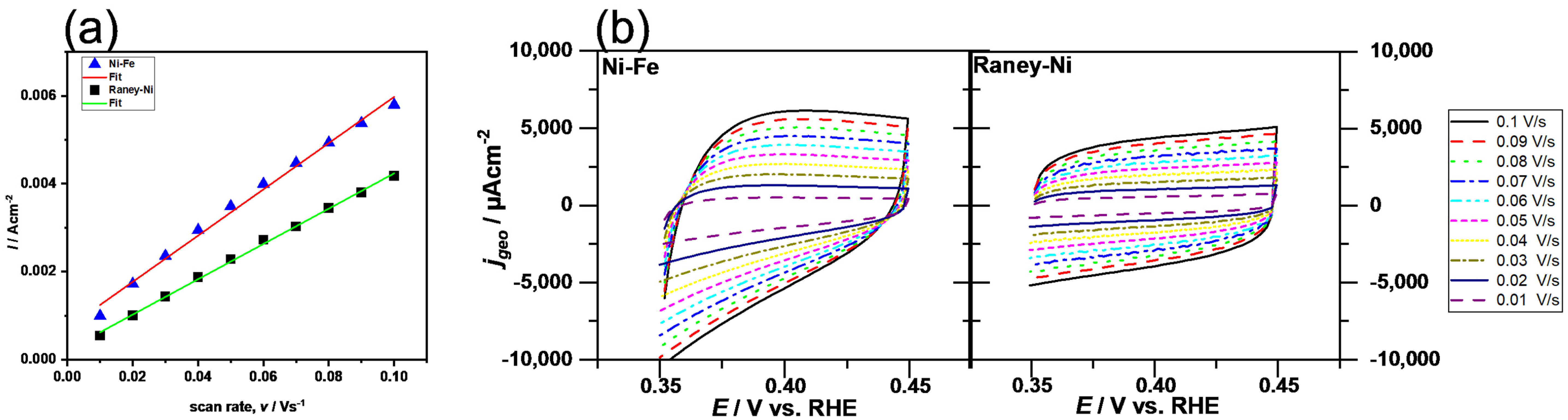
  • CV: determining Cdl at OCP after HER.
Steady-state polarization curves were also recorded to display the Tafel plot. The determination of the Cdl from the CV data and the reason for the pretreatment CV are given in a previous publication [69].

2.6. In Situ Cell Tests

The electrolysis of prepared separator membranes was carried out in a single zero-gap-based configuration cell with a separator membrane consisting of 85 wt.% ZTA and 15 wt.% PSU, taking Zirfon® as the reference material. The cell had an active area of around 34.56 cm2. The cell contained the current collectors, bipolar plates, and nickel-based porous transport layers (PTLs). The performance of the cells with the prepared membrane was analyzed at 80 °C, and the KOH electrolyte was circulated at different flow rates. The catalyst applied at the cathode side was Raney nickel (composed of nickel only) and at the anode side Nickel–Iron (Ni-Fe) LDH was used. With both catalysts, nickel foam was also additionally used as the catalyst. The voltage of the cell was recorded at current densities ranging from 0 to 2000 mA cm–2 with a potentiostat (Advanced Power System Keysight N7970A, Agilent Technologies). Galvanostatic electrochemical impedance spectroscopy (GEIS) was used for measuring at 200 mA cm−2 of current density within the range between 0.1 MHz and 1 Hz.

3. Results

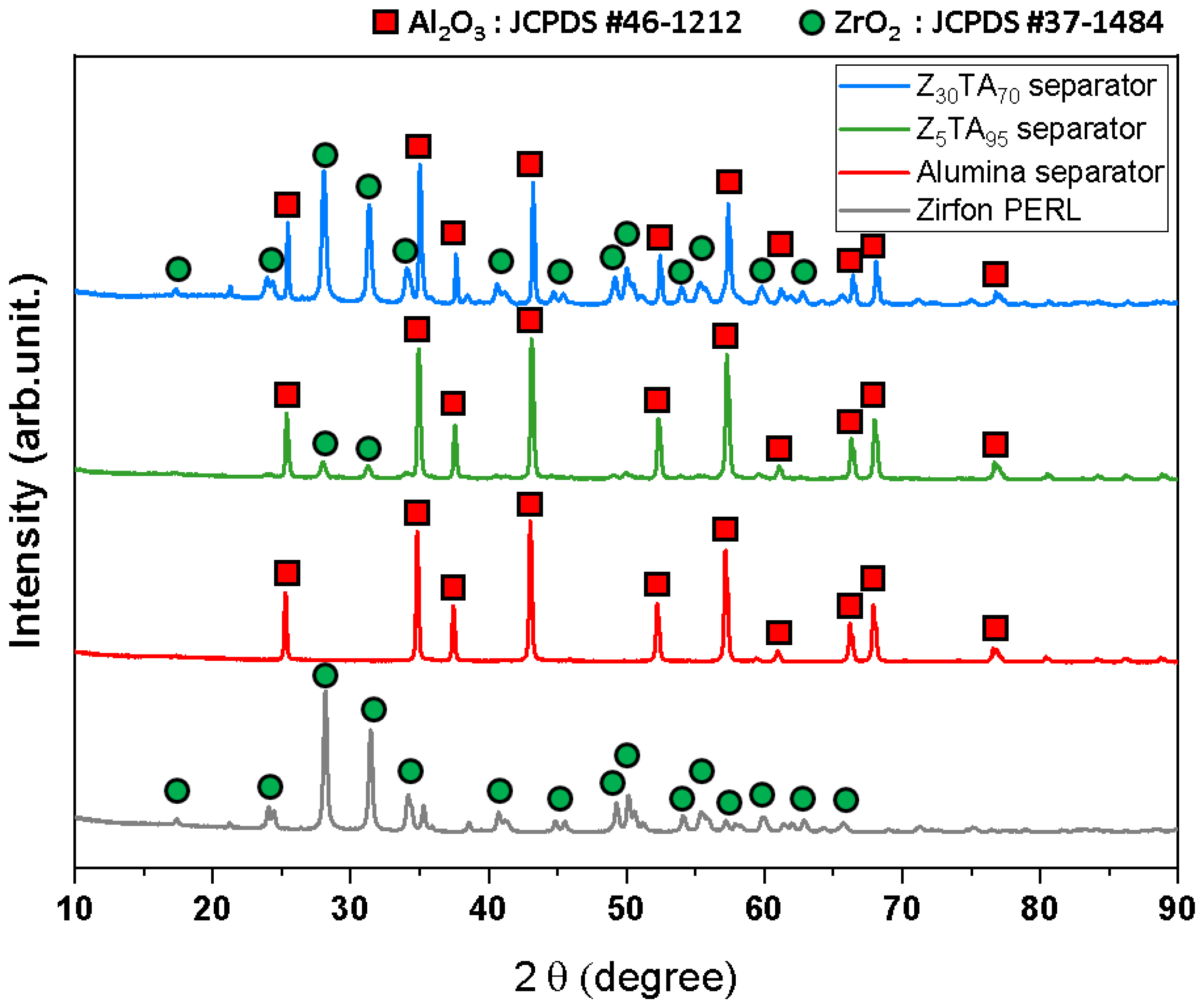
3.1. Characterization of Prepared Separator Membranes

Figure 1 shows the X-ray diffraction analyses of commercial Zirfon® and the prepared separator membranes, which were carried out to confirm the crystal structure. The presence of the monoclinic zirconia phase in Zirfon® was confirmed by the standard card of JCPDS #37-1484 [71]. The alumina separator exhibited a hexagonal structure by JCPDS #46-1212 [72]. In the Z5TA95 and Z30TA70 separator membranes (zirconia nanoparticles in alumina matrix), the presence of large hexagonal phase and smaller monoclinic phases was confirmed by JCPDS #46-1212 and JCPDS #37-1484, respectively.
Scanning electron microscopy is utilized for the morphological analysis of ZTA separator membranes and Zirfon®. Figure 2 represents the cross-sectional view of the ZTA separator membrane and Zirfon®.
The reference Zirfon® was topped by a few-micrometer-thick rich polysulfone (PSU) layer (Figure 2e). A random distribution of zirconia nanoparticles and PSU composite under the rich polysulfone (PSU) layer was visible in the case of Zirfon® (Figure 2e). No such layer was observed in the alumina separator membrane (Figure 2b,f). Additionally, such a thick layer was also not observed on the top of the Z5TA95 (Figure 2c,g) and Z30TA70 separator membranes (Figure 2d,h). The alumina separator membrane exhibits that the particle shape of the alumina matrix is mainly spherical (Figure 2b,f). The Z5TA95 membranes, which have a very low content of zirconia (only 5%), also exhibit the presence of a spherical matrix in Figure 2c,g, with the increase of zirconia content in the alumina matrix; as in Z30TA70, the original spherical shape of particles disappears in Figure 2d,h. ZTA nanoparticles are properly mixed with polysulfone, i.e., distributed uniformly and display good compatibility with polymer as shown in Figure 2c,h. SEM-EDS analysis confirmed the presence of Al in the alumina separator membrane (Figure 2j). It can be confirmed, that Al and Zr are present in the ZTA separator membrane (Figure 2k,l). Mapping also exhibits that zirconia particles are present at the boundary of the alumina matrix and are uniformly distributed with alumina (Figure 2k,l).
Figure 3a shows the mercury pore size distribution of ZTA separator membranes and reference Zirfon®. Separator membranes are largely comprised of nanometer-size interconnected ZTA pores. Small pores of 10 to 50 nm represent the pores between the ZTA nanoparticles and relatively larger, macro-sized pores of are correlated with the interconnected polysulfone pore network. Zirfon® gave an initial broad peak within the range of 10–50 nm and a second narrow and large peak having strong intensity at around 1000 nm pore size. However, the ZTA-based separator membranes displayed a reduction in the micro-sized type pores with a decrease in the intensity as well. The first peak intensity of the alumina and Z5TA95 separator membranes (at around 70 nm) was greater than that of the Z30TA70 separator membrane, which indicates that alumina and Z5TA95 have a smaller average pore size as compared to Z30TA70. However, the prepared separators exhibited a wide distribution of pores from 50 to 100 nm and demonstrated higher-intensity values as compared to Zirfon®. The Z30TA70 exhibits the second peak of large intensity at greater than 1000 nm. The physical characteristics of the separator membranes and Zirfon® are summarized in Table 2. The largest pore size (~125.10 nm) was observed in the Z30TA70 separator membrane. The reference Zirfon® represented the average pore size value (~99 nm), which was lower than that of Z30TA70. The alumina separator membrane had the smallest average pore size value (~79.63 nm). It was noted that the ZTA separator membranes exhibited a wider pore distribution from 50 to 100 nm, which is related to the peak shift onto the left side toward the smaller pore diameters in comparison with the reference Zirfon® (Figure 3a). The alumina separator membrane having a spherical pore shape exhibited a large pore area (16.39 m2 g−1) (Table 2), in comparison to the Z30TA70 membranes, which showed a 13.65 m2 g−1 pore area. Z30TA70 with a large average pore diameter exhibited uniform pore distribution throughout the structure as shown in Figure 2h.
The ohmic resistance of the separator membrane and Zirfon® is shown in Figure 3b. KOH is mostly used as an electrolyte in the case of an alkaline electrolyzer. Ionic conductivity is supplied by an aqueous alkaline solution that penetrates through the pores of the separator membrane. The ionic conductivity of the separator membrane is directly linked to their ionic resistance. The ionic conductivity of the KOH electrolyte used in this study was 0.4468 S/cm. Zirfon® (prepared with 40 nm zirconia nanoparticles) exhibited area resistance around 0.3 Ω·cm2. The ohmic resistance of the prepared separator membranes was lower than that of Zirfon®. The separator membrane containing only alumina particles (Alumina: ZrO2; 100:0) showed an area resistance of around 0.172 Ω·cm2, which is lower than that of commercial Zirfon®. The area resistance decreased further when we used the ZTA separator membrane. The Z5TA95 exhibited an area resistance of 0.159 Ω·cm2. It reduced further to 0.15 Ω·cm2 as the amount of zirconia in alumina increased to 30 wt.%, i.e., Z30TA70 (Figure 3b).
The ionic conductivity is supplied by the KOH electrolyte solution, which permeates through the pores of the porous separator membrane. The porous separator membrane separates the evolved gases [73]. The KOH electrolyte solution can easily pass across the separator membrane due to the induced differential pressure between the two electrode sides, i.e., the cathodic and anodic sides. With the increase in the amount of porosity, the permeability values also increased. The highly porous separator membranes exhibited low ionic resistance; however, they demonstrated high permeability. Therefore, there is a compromise between the two most important properties of separator membranes, i.e., ohmic resistance and H2 gas permeability. The reference Zirfon® contained micropores having strong intensity values as shown in Figure 3a. The dissolved hydrogen gas in the electrolyte can pass through the micropores of porous Zirfon® due to the induced differential pressure [74], which gives rise to a low partial load capability of AWEs. On the other hand, the polymer-based electrolyte membrane in the case of a PEM electrolyzer normally consists of nanopores of a few nanometers around (2–5 nm), due to which they showed low crossover of gas induced by the differential pressure. To reduce the gas crossover induced by the difference of pressure, porous separator membranes with small pores can be developed.
Zirfon® exhibited high H2 permeability in the order of 26.8 × 10⁻¹² mol cm−1 s−1 bar−1, as seen in Figure 3c. However, in comparison to the reference Zirfon®, the prepared ZTA separator membranes showed less H2 permeability. The 100% Al2O3 separator membrane exhibited H2 permeability of 14.2 × 10⁻¹² mol cm−1 s−1 bar−1. With the increase in the amount of zirconia in alumina, permeability decreases. The ZTA 5% separator membrane, Z5TA95, showed H2 permeability of around 11.2 × 10⁻¹² mol cm−1 sec−1 bar−1; however, Z30TA70 showed a further reduction in H2 permeability, having 10.7 × 10⁻¹² mol cm−1 s−1 bar−1 in Figure 3c.

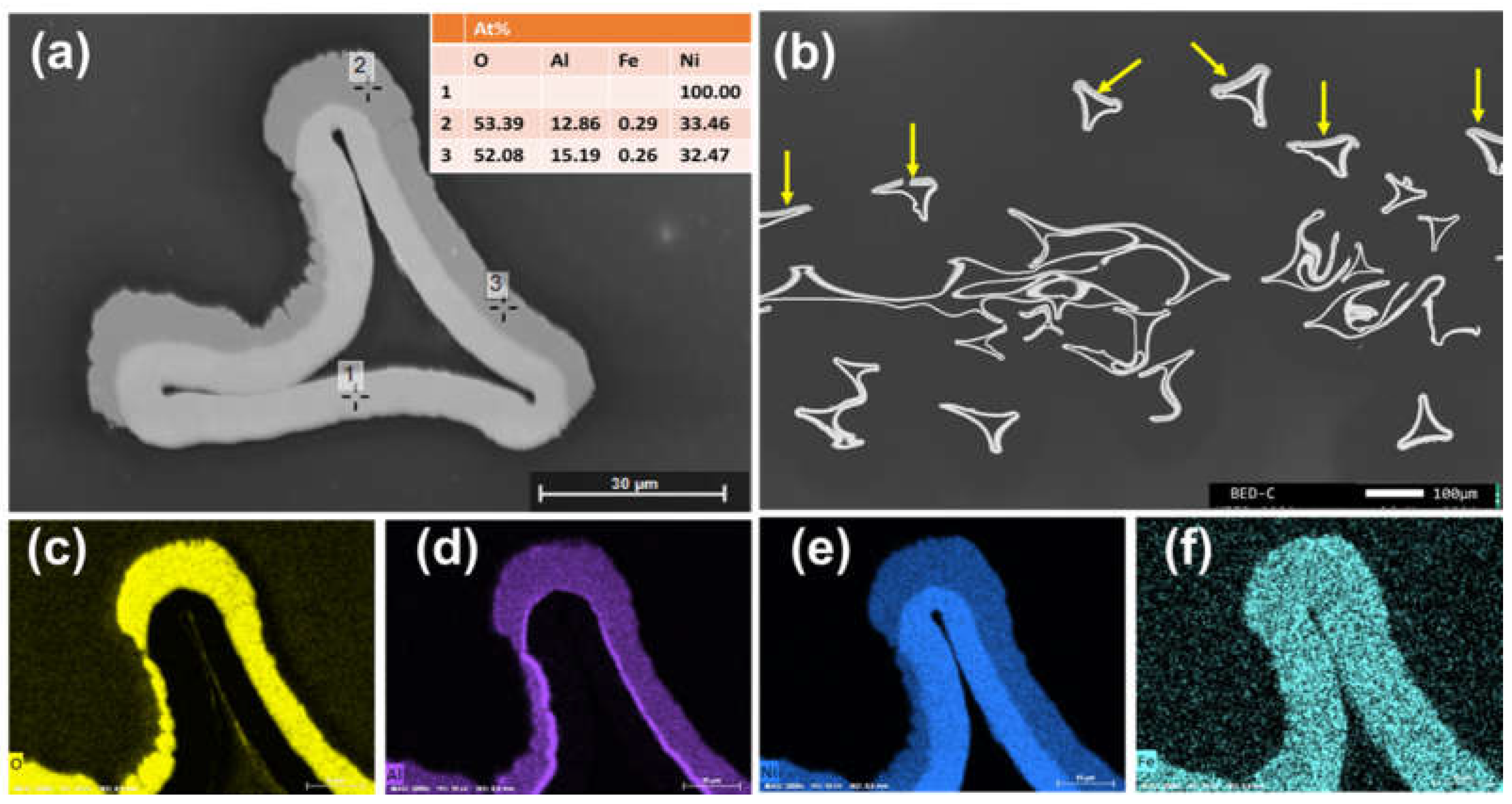
Characterization of the Anode and Cathode Material

The cross-section analysis of the Raney-Ni cathode is given in Figure 4 in the as-leached state before the electrochemical tests. Due to the selective coating onto only one side of the substrate, the Raney-Ni coating could only be observed at one side (marked in Figure 4b with yellow arrows). The layer thickness was around 5–10 µm. The SEM-EDX analysis (Figure 4a) revealed that the Al coating has transformed into a Ni-Al alloy. The Al content was still quite high after the leaching process (see also Figure 4d). No delamination of the Raney-Ni layer was detected.
Contrary to the Raney-Ni electrode, the Ni-Fe preparation process leads to a homogeneously coated Fe-foam with an onion-like Ni-Fe-S layer (see Figure 5). The layer thickness was around 10–20 µm. Besides the outer sides, also at the inner sides of the foams, the Ni-Fe-S layer could be seen. The elemental mapping revealed that the coating consisted of two separated components: Ni-S and Fe-O-S. The Ni-S appeared to be the matrix and Fe-O-S was embedded in the matrix. The sulfur content in the sample was introduced by the electroplating process. High porosity was observed.
The samples were electrochemically investigated using the test protocol given in Section 2.5. The results in Figure 6 reveal that the Raney-Ni-coated foam exhibited an overpotential after 5 h of η500 = 174 mV. A slight increase of potential was detectable (~+5 mV/h).
The high electrocatalytic activity toward the HER was also reflected by the high surface area (Cdl = 0.040 F/cm2, extracted from Figure 7a) and the low Tafel slope of 79.9 mV/dec (in the high current density region). The high Cdl value indicates that the high activity was a result of the high surface area (extrinsic activity).
The Ni-Fe material in turn showed a much higher absolute overpotential (here for the OER η500 = 274 mV); however, a decrease of the overpotential over time (−1.6 mV/h) was seen. As can be seen in Figure 7b, the CVs for the anodic region are not parallel to the x-axis. Thus, the determination of the Cdl was subject to uncertainty. However, the average Cdl of 0.053 F/cm2 was within the range of the anodic Cdl (0.061 F/cm2) and the cathodic Cdl (0.044 F/cm2). The onion-shell structure seems to contribute to the formation of a high electrocatalytic surface. The Tafel plot exhibited a Tafel slope of 90.6 mV/dec in the high current density region. It can be concluded from the electrochemical analysis that the Ni-Fe anode material activity is mainly limited by low intrinsic activity. This cannot be overcompensated by the high surface area.

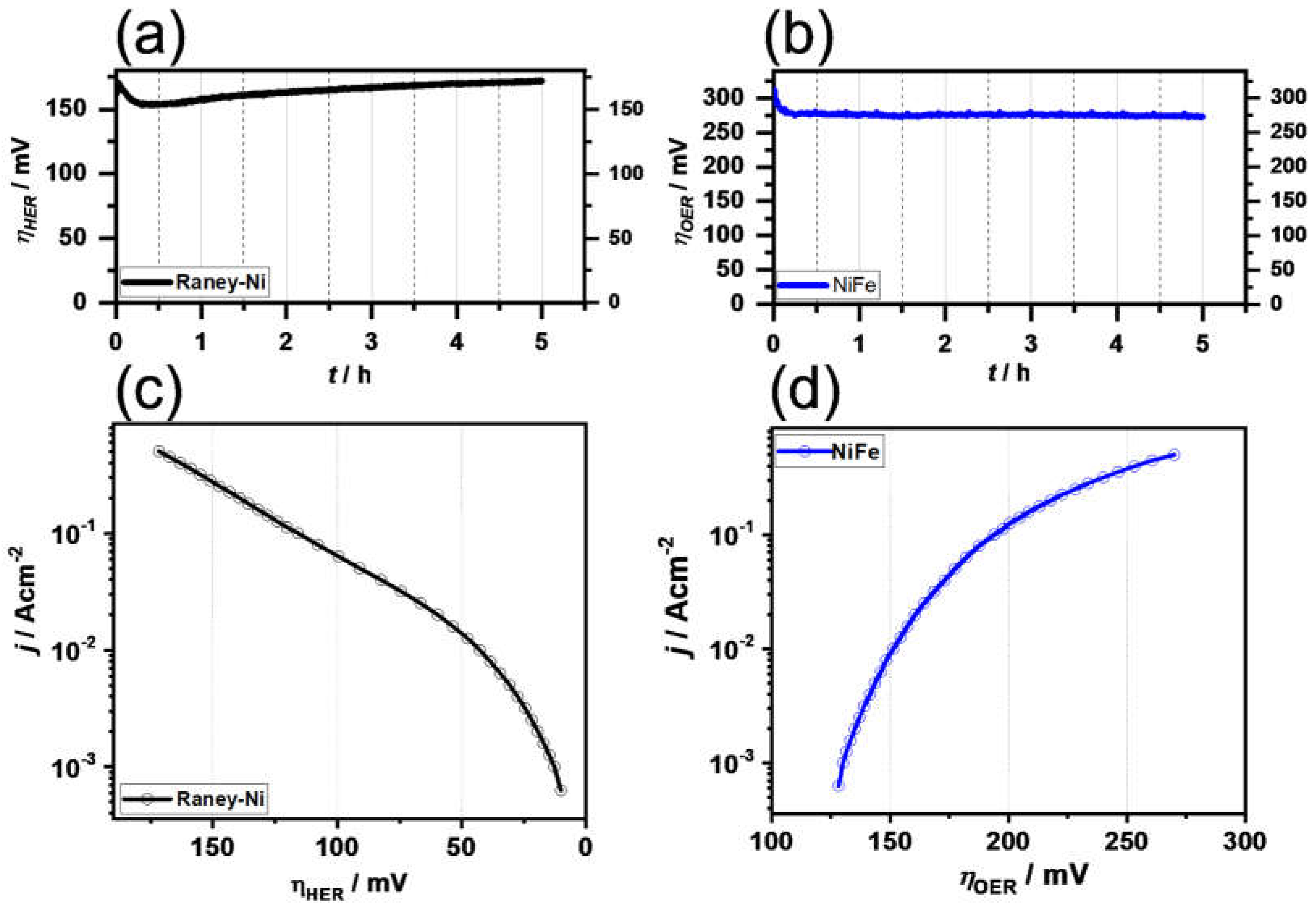
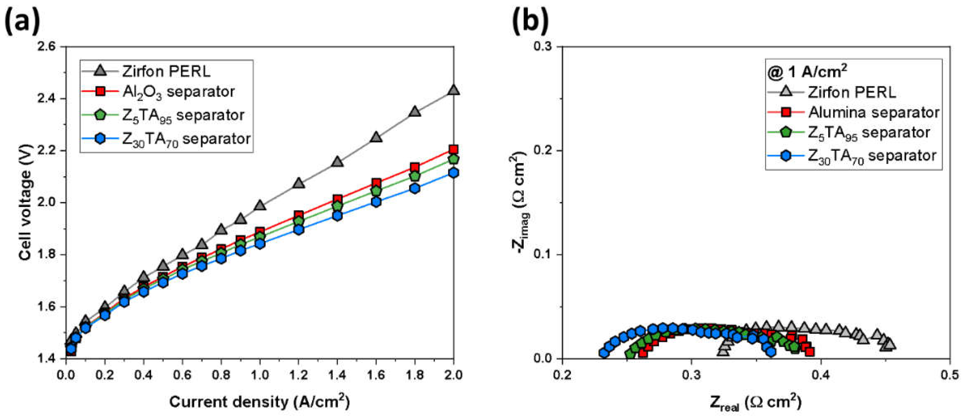
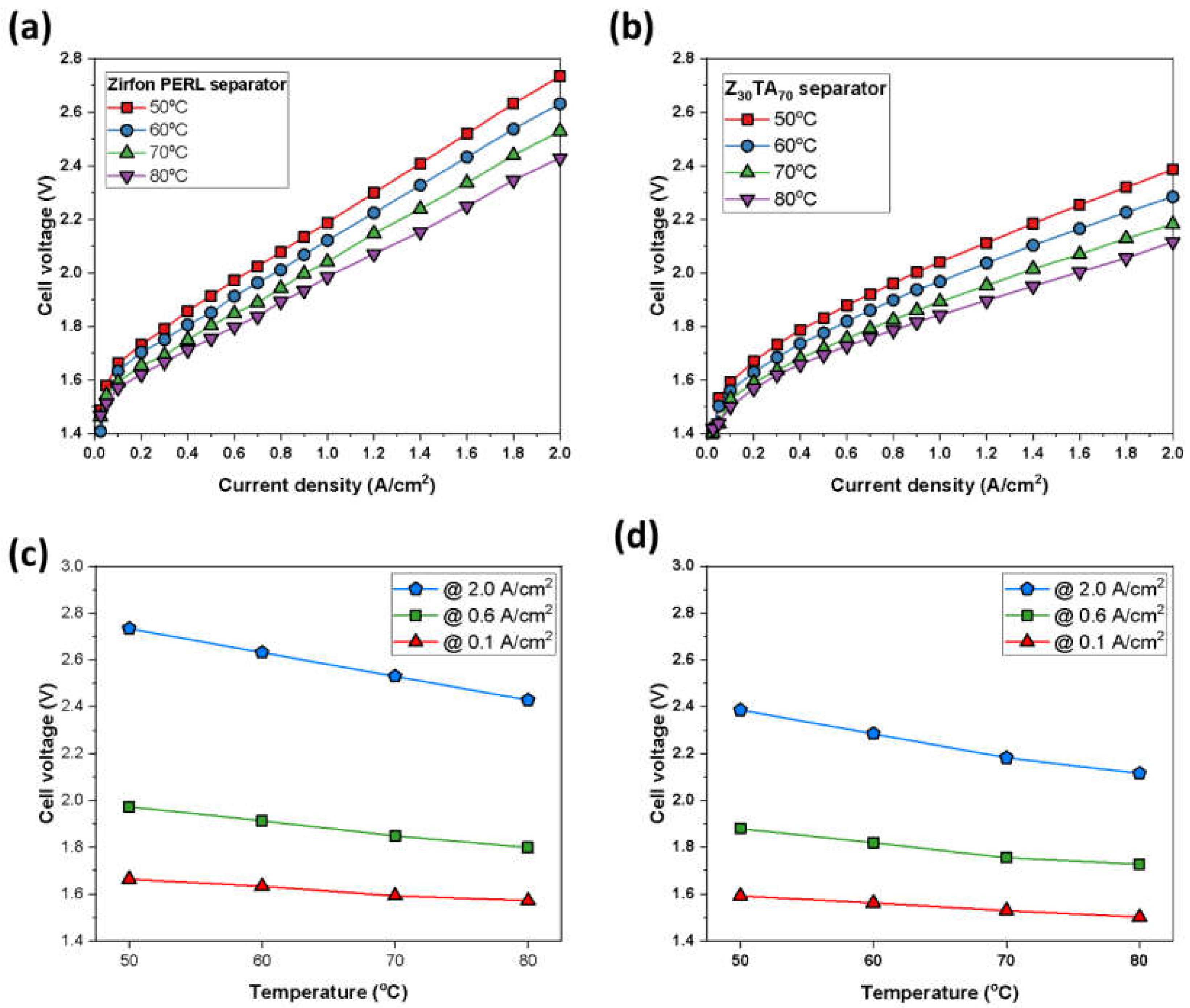
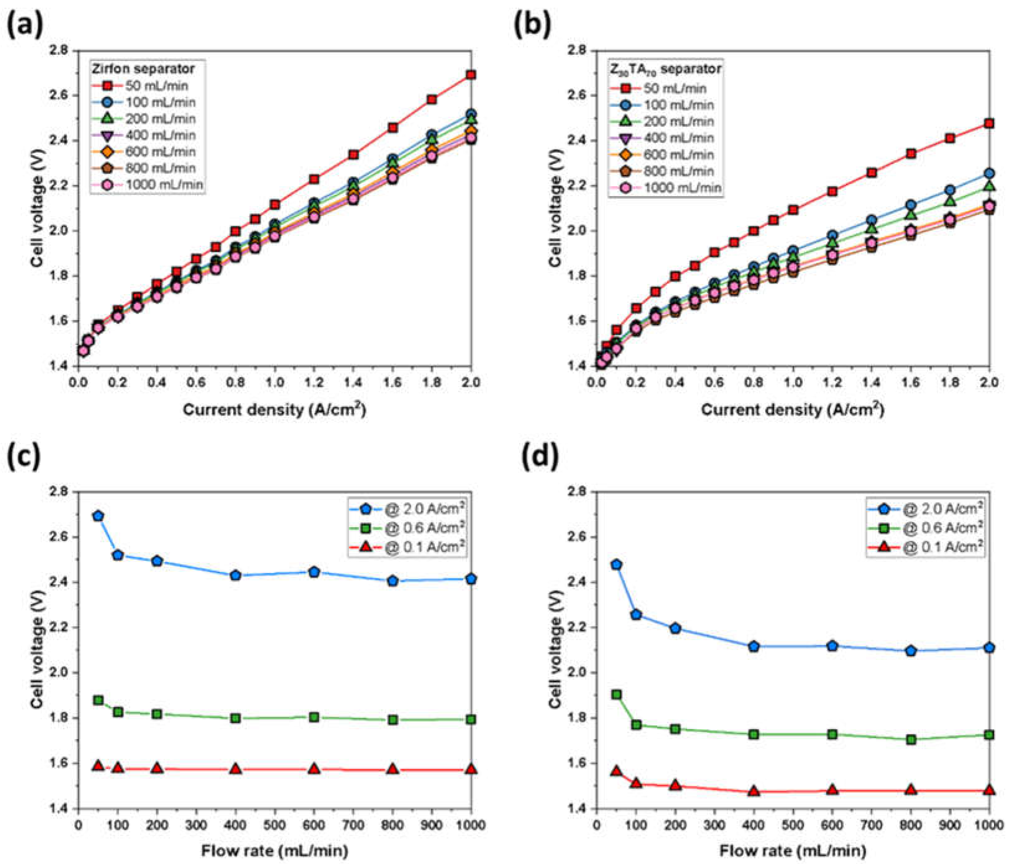
3.2. Cell Test of the Separator Membrane

The electrolysis of ZTA separator membranes was performed by using different metallic catalysts and nickel foams as the porous transport layer. The polarization properties of cells combined with different separator membranes can be seen in Figure 8a.
The electrolysis test was conducted at 80 °C temperature by using 30 wt.% aqueous solutions of KOH and electrodes (Raney nickel on cathode and Ni-Fe LDH at anode). The cell carrying the Z30TA70 separator membrane exhibited a much-improved performance of 2.1 V at 2 A/cm2 in comparison to the reference Zirfon®, which showed 2.41 V at 2 A/cm2. This makes Z30TA70 more efficient as compared to Zirfon®. The other separator membranes also show improved performance as compared to Zirfon® as shown in Figure 8a. The ohmic resistance of the Z30TA70 separator membrane was analyzed by using the Nyquist plot. Figure 8b shows the Nyquist plot of impedance spectra at 1 A/cm2. The equivalent circle largely consists of ohmic resistance, activation resistance, and mass-transport resistance. The high-frequency resistance (HFR) is demonstrated by the intercepts of the Nyquist plot with the x-axis at higher frequency (left portion on Nyquist plot), representing the ohmic resistance of the cell. The ohmic resistance is the resistance caused by the flow of current through the cell, which is mainly due to the contribution from the membrane. The area resistance measure ex situ in Figure 3b matched well with the in situ internal resistance of Figure 8b. The middle portion of the equivalent circuit model exhibited the activation loss. The activation loss results from the kinetics of electrodes. Only one semicircle from the high to the middle frequency with a similar size was observed for all the membrane separators, which is attributed to the use of the same electrodes. The mass-transport limitation and resistance were not observed in this study.
The performance of the improved Z30TA70 separator membrane was analyzed by using different electrolyte concentrations (10, 20, and 30 wt.%), by varying the temperature of electrolysis from 50 to 80 °C and by using various KOH flow rates. Figure 9b shows that the Z30TA70 membrane exhibited improved performance in the 30 wt.% KOH solution. It exhibited 2.1 V at 2 A/cm2. This enhanced performance was due to the uniform distribution of Z30TA70 in polymer matrix (Figure 2h), and the low ohmic resistance (0.15 Ω·cm2) of Z30TA70 (Figure 3b). However, Zirfon® showed the same current density at a higher voltage of 2.4 V (Figure 9a).
The low performance of Zirfon® in comparison to Z30TA70 was due to the random distribution of zirconia nanoparticles in polymer matrix (Figure 2e), and the higher ohmic resistance 0.3 Ω·cm2. Z30TA70 exhibited reduced performance in 20 wt.% and 10 wt.% KOH (Figure 9b); however, it was still much better than Zirfon®. The effect of KOH concentration on cell voltage at different current densities was also analyzed (Figure 9c,d). There was no change in the performance of Z30TA70 and Zirfon® at various KOH concentrations at a low current density of 0.1 A/cm2 (Figure 9c,d). On the contrary, at a higher current density of 2 A/cm2, the performances of both Z30TA70 and Zirfon® were enhanced by increasing the KOH concentration from 10 to 30 wt.%. Zirfon® exhibited a high cell voltage of 3.6 V at a high current density of 2 A/cm2 owing to the use of diluted aqueous KOH solution of 10 wt.%. It is well known that ionic conductivity values decrease with lower KOH concentration, which implies that the internal resistance of Zirfon® is relatively higher than that of our prepared membranes.
The polarization properties of Z30TA70 were also studied by varying the temperature during the test. The Z30TA70 exhibited excellent performance at 80 °C; however, performance was reduced by lowering the temperature from 80 to 50 °C due to the increase in the viscosity of KOH solution at low temperature. It indicates that 80 °C is the optimum electrolysis temperature for AWEs (Figure 10b).
Zirfon® also showed reduced performance at lower temperatures and exhibited improved performance at 80 °C (Figure 10a); still, it showed lower performance than Z30TA70 (Figure 10a,b). The effect of temperature on cell voltage at different current densities was also analyzed (Figure 10c,d). At a higher current density of 2 A/cm2, the performances of both Z30TA70 and Zirfon® were enhanced by increasing the temperature to 80 °C (Figure 10c,d). The reason is that, at high temperatures, the viscosity of the KOH solution decreases, which increases the flow of KOH.
The polarization characteristics of Z30TA70 were also examined by varying the KOH circulation rate. By increasing the circulation rate of KOH, the performance of Z30TA70 also improved. Z30TA70 demonstrated 2 A/cm2 at 2.45 V at 50 mL/min KOH flow rate. On increasing the flow rate to 800 mL/min, Z30TA70 exhibited improved performance of 2 A/cm2 at 2.1 V due to an increase in KOH flow through the separator membrane (Figure 11b). For comparison, Zirfon® showed reduced performance as compared to Z30TA70 at different flow rates due to its higher ohmic resistance and gas permeability (Figure 11a). The effect of the circulation rate of KOH on cell voltage at different current densities was also analyzed (Figure 11c,d). At a higher current density of 2 A/cm2, the performances of both Z30TA70 and Zirfon® were enhanced by increasing the KOH circulation rate. This was mainly due to the rapid flow of KOH through the separator membrane. However, Z30TA70 exhibited much better performance than Zirfon® (Figure 11c,d).
To investigate the performance of Z30TA70, a stability test was performed in harsh conditions. Z30TA70 was immersed in 35 wt.% aqueous solutions of KOH at 100 °C for four weeks. The stability was checked after two weeks and four weeks by conducting XRD and BET analysis, as shown in Figure 12.
No significant change in the XRD peak was observed after the stability test (Figure 12a). The physical properties of Z30TA70 after the stability test are given in Table 3. There was no change in BET surface area after the stability test. A slight increase in pore size was observed after the stability test, which also led to a small increase in the volume of the pore (Figure 12b). However, this change was very negligible and did not affect the overall properties of Z30TA70. The stability test indicated that Z30TA70 had very little degradation in harsh conditions.

4. Conclusions

The development of a highly ionic conductive and durable porous separator membrane is vital for enhancing the performance of an alkaline water electrolyzer. This paper suggested a Z30TA70-based separator membrane that exhibits high ionic conductivity and low gas permeability in comparison to state-of-the-art Zirfon®. The Z30TA70 separator membrane, having a low thickness of 430 μ m, exhibited low ohmic resistance 0.15 Ω·cm2 and lower hydrogen gas permeability 10.7 × 10⁻¹² mol cm−1 s−1 bar−1. Raney nickel and Ni-Fe LDH electrodes were prepared successfully. Electrochemical investigations were carried out in which Raney-Ni-coated foam exhibited an overpotential after 5 h of η500 = 174 mV and exhibited high electrocatalytic activity toward the HER owing to its high surface area. On the other hand, the Ni-Fe LDH showed a much higher absolute overpotential (here, for the OER η500 = 274 mV). It can be concluded from the electrochemical analysis that the Ni-Fe anode material activity is mainly limited by low intrinsic activity. This cannot be overcompensated by the high surface area. The electrolytic cell containing Z30TA70 separator membrane having Raney nickel as cathode and Ni-Fe LDH as anode and 30 wt.% KOH electrolyte demonstrated 2 A/cm2 at 2.1 V. The performance of this improved Z30TA70 separator membrane was also analyzed by varying the KOH electrolyte concentration, the KOH flow rate, and the electrolysis temperature. The results demonstrate that the Z30TA70 separator membrane gives an improved performance as compared to the reference Zirfon®. The results presented in this paper make the Z30TA70 separator membrane a suitable material for highly advanced and efficient alkaline water electrolyzer systems.

Author Contributions

Conceptualization, W.-C.C.; methodology, M.F.A., H.I.L. and C.I.B.; validation, M.F.A., H.I.L. and C.I.B.; formal analysis, M.F.A., S.L., S.-K.K., T.W. and C.I.B.; investigation, M.F.A., H.I.L. and C.I.B.; data curation, W.-C.C., S.-K.K. and M.F.A.; writing—original draft preparation, W.-C.C., M.F.A. and C.I.B.; writing—review and editing, W.-C.C., S.L., T.W., C.I.B. and M.F.A.; visualization, W.-C.C.; supervision, W.-C.C.; project administration, W.-C.C.; funding acquisition, W.-C.C. All authors have read and agreed to the published version of the manuscript.

Funding

This work was supported by the Korea Institute of Energy Technology Evaluation and Planning (KETEP) and the Ministry of Trade, Industry, and Energy (MOTIE) of the Republic of Korea (Project Number: 20218520040040, 2019281010007A, and 20203030040030). This research was also supported by the Hydrogen Energy Innovation Technology Development Program of the National Research Foundation of Korea (NRF) funded by the Korean government (Ministry of Science and ICT (MSIT)) (NRF-2019M3E6A1064020).

Institutional Review Board Statement

Not applicable.

Informed Consent Statement

Not applicable.

Data Availability Statement

Data that support the findings of this study are included in the article.

Conflicts of Interest

The authors declare no conflict of interest.

Nomenclature

KPermeability of the electrolyte (cm2)
S H 2 Hydrogen gas solubility in the electrolyte (mol m–3 bar–1)
η Electrolyte’s viscosity (bar s)
ΔpDifferential pressure (bar)
AWEAlkaline water electrolysis
GEISGalvanostatic electrochemical impedance spectroscopy
PTLPorous transport layer
ZTAZirconia-toughened alumina
RPMRevolutions per minute

References

  1. Götz, M.; Lefebvre, J.; Mörs, F.; McDaniel Koch, A.; Graf, F.; Bajohr, S.; Reimert, R.; Kolb, T. Renewable Power-to-Gas: A technological and economic review. Renew. Energy 2016, 85, 1371–1390. [Google Scholar] [CrossRef] [Green Version]
  2. Tjarks, G.; Mergel, J.; Stolten, D. Dynamic Operation of Electrolyzers—Systems Design and Operating Strategies. In Hydrogen Science and Engineering: Materials, Processes, Systems and Technology; Wiley-VCH Verlag GmbH & Co.: Weinheim, Germany, 2016; pp. 309–330. [Google Scholar] [CrossRef]
  3. Santos, D.M.F.; Sequeira, C.A.C.; Figueiredo, J.L. Hydrog. production by alkaline water electrolysis. Quim. Nova 2013, 36, 1176–1193. [Google Scholar] [CrossRef]
  4. Albonetti, S.; Perathoner, S.; Quadrelli, A.E. Horizons in Sustainable Industrial Chemistry and Catalysis; Elsevier: Amsterdam, The Netherlands, 2019. [Google Scholar]
  5. Takach, M.; Sarajlić, M.; Peters, D.; Kroener, M.; Schuldt, F.; von Maydell, K. Review of Hydrog. Production Techniques from Water Using Renewable Energy Sources and Its Storage in Salt Caverns. Energies 2022, 15, 1415. [Google Scholar] [CrossRef]
  6. Minakshi, M.; Higley, S.; Baur, C.; Mitchell, D.R.G.; Jones, R.T.; Fichtner, M. Calcined chicken eggshell electrode for battery and supercapacitor applications. RSC Adv. 2019, 9, 26981–26995. [Google Scholar] [CrossRef] [Green Version]
  7. Divakaran, A.M.; Hamilton, D.; Manjunatha, K.N.; Minakshi, M. Design, Development and Thermal Analysis of Reusable Li-Ion Battery Module for Future Mobile and Stationary Applications. Energies 2020, 13, 1477. [Google Scholar] [CrossRef] [Green Version]
  8. Wickramaarachchi, W.A.M.K.P.; Minakshi, M.; Gao, X.; Dabare, R.; Wong, K.W. Hierarchical porous carbon from mango seed husk for electro-chemical energy storage. Chem. Eng. J. Adv. 2021, 8, 100158. [Google Scholar] [CrossRef]
  9. Minakshi, M.; Mitchell, D.R.G.; Baur, C.; Chable, J.; Barlow, A.J.; Fichtner, M.; Banerjee, A.; Chakraborty, S.; Ahuja, R. Phase evolution in calcium molybdate nanoparticles as a function of synthesis temperature and its electrochemical effect on energy storage. Nanoscale Adv. 2019, 1, 565–580. [Google Scholar] [CrossRef] [Green Version]
  10. Minakshi, M.; Mitchell, D.R.; Jones, R.T.; Pramanik, N.C.; Jean-Fulcrand, A.; Garnweitner, G. A hybrid electrochemical energy storage device using sustainable electrode materials. ChemistrySelect 2020, 5, 1597–1606. [Google Scholar] [CrossRef]
  11. Sharma, P.; Minakshi, M.; Whale, J.; Jean-Fulcrand, A.; Garnweitner, G. Effect of the Anionic Counterpart: Molybdate vs. Tungstate in Energy Storage for Pseudo-Capacitor Applications. Nanomaterials 2021, 11, 580. [Google Scholar] [CrossRef]
  12. Divakaran, A.M.; Minakshi, M.; Bahri, P.A.; Paul, S.; Kumari, P.; Manjunatha, K.N. Rational design on materials for developing next generation lithium-ion secondary battery. Prog. Solid State Chem. 2021, 62, 100298. [Google Scholar] [CrossRef]
  13. Stolten, D. Hydrogen and Fuel Cells: Fundamentals, Technologies, and Applications; John Wiley & Sons: Hoboken, NJ, USA, 2010. [Google Scholar]
  14. Gandía, L.M.; Oroz, R.; Ursúa, A.; Sanchis, P.; Diéguez, P.M. Renewable Hydrog. Production: Performance of an Alkaline Water Electrolyzer Working under Emulated Wind Conditions. Energy Fuels 2007, 21, 1699–1706. [Google Scholar] [CrossRef]
  15. Clarke, R.; Giddey, S.; Badwal, S. Stand-alone PEM water electrolysis system for fail safe operation with a renewable energy source. Int. J. Hydrog. Energy 2010, 35, 928–935. [Google Scholar] [CrossRef]
  16. Millet, P.; Andolfatto, F.; Durand, R. Design and performance of a solid polymer electrolyte water electrolyzer. Int. J. Hydrog. Energy 1996, 21, 87–93. [Google Scholar] [CrossRef]
  17. David, M.R.; Ocampo-Martínez, C.; Sánchez-Peña, R. Advances in alkaline water electrolyzers: A review. J. Energy Storage 2019, 23, 392–403. [Google Scholar] [CrossRef] [Green Version]
  18. Grigoriev, S.; Millet, P.; Korobtsev, S.; Porembskiy, V.; Pepic, M.; Etievant, C.; Puyenchet, C.; Fateev, V. Hydrogen safety aspects related to high-pressure polymer electrolyte membrane water electrolysis. Int. J. Hydrog. Energy 2009, 34, 5986–5991. [Google Scholar] [CrossRef]
  19. Lettenmeier, P.; Wang, R.; Abouatallah, R.; Helmly, S.; Morawietz, T.; Hiesgen, R.; Kolb, S.; Burggraf, F.; Kallo, J.; Gago, A.; et al. Durable Membrane Electrode Assemblies for Proton Exchange Membrane Electrolyzer Systems Operating at High Current Densities. Electrochim. Acta 2016, 210, 502–511. [Google Scholar] [CrossRef] [Green Version]
  20. Reier, T.; Nong, H.N.; Teschner, D.; Schlögl, R.; Strasser, P. Electrocatalytic oxygen evolution reaction in acidic environments–reaction mechanisms and catalysts. Adv. Energy Mater. 2017, 7, 1601275. [Google Scholar] [CrossRef]
  21. Schmidt, O.; Gambhir, A.; Staffell, I.; Hawkes, A.; Nelson, J.; Few, S. Future cost and performance of water electrolysis: An expert elicitation study. Int. J. Hydrog. Energy 2017, 42, 30470–30492. [Google Scholar] [CrossRef]
  22. Estermann, T.; Newborough, M.; Sterner, M. Power-to-gas systems for absorbing excess solar power in electricity distribution networks. Int. J. Hydrog. Energy 2016, 41, 13950–13959. [Google Scholar] [CrossRef]
  23. Olivier, P.; Bourasseau, C.; Bouamama, P.B. Low-temperature electrolysis system modelling: A review. Renew. Sustain. Energy Rev. 2017, 78, 280–300. [Google Scholar] [CrossRef]
  24. Qadrdan, M.; Abeysekera, M.; Chaudry, M.; Wu, J.; Jenkins, N. Role of power-to-gas in an integrated gas and electricity system in Great Britain. Int. J. Hydrog. Energy 2015, 40, 5763–5775. [Google Scholar] [CrossRef]
  25. Stelmachowski, P.; Duch, J.; Sebastián, D.; Lázaro, M.J.; Kotarba, A. Carbon-Based Composites as Electrocatalysts for Oxygen Evolution Reaction in Alkaline Media. Materials 2021, 14, 4984. [Google Scholar] [CrossRef] [PubMed]
  26. Abbasi, R.; Setzler, B.P.; Lin, S.; Wang, J.; Zhao, Y.; Xu, H.; Pivovar, B.; Tian, B.; Chen, X.; Wu, G.; et al. A Roadmap to Low-Cost Hydrogen with Hydroxide Exchange Membrane Electrolyzers. Adv. Mater. 2019, 31, e1805876. [Google Scholar] [CrossRef]
  27. Ju, W.; Heinz, M.; Pusterla, L.; Hofer, M.; Fumey, B.; Castiglioni, R.; Pagani, M.; Battaglia, C.; Vogt, U.F. Lab-Scale Alkaline Water Electrolyzer for Bridging Material Fundamentals with Realistic Operation. ACS Sustain. Chem. Eng. 2018, 6, 4829–4837. [Google Scholar] [CrossRef]
  28. Guilbert, D.; Vitale, G. Hydrogen as a Clean and Sustainable Energy Vector for Global Transition from Fossil-Based to Zero-Carbon. Clean Technol. 2021, 3, 881–909. [Google Scholar] [CrossRef]
  29. Yodwong, B.; Guilbert, D.; Phattanasak, M.; Kaewmanee, W.; Hinaje, M.; Vitale, G. AC-DC Converters for Electrolyzer Applications: State of the Art and Future Challenges. Electronics 2020, 9, 912. [Google Scholar] [CrossRef]
  30. Zeng, K.; Zhang, D. Recent progress in alkaline water electrolysis for Hydrogen production and applications. Prog. Energy Combust. Sci. 2010, 36, 307–326, Corrigendum in Prog. Energy Combust. Sci. 2011, 37, 631. [Google Scholar] [CrossRef]
  31. Marini, S.; Salvi, P.; Nelli, P.; Pesenti, R.; Villa, M.; Berrettoni, M.; Zangari, G.; Kiros, Y. Advanced alkaline water electrolysis. Electrochim. Acta 2012, 82, 384–391. [Google Scholar] [CrossRef]
  32. Saur, G. Wind-To-Hydrogen Project: Electrolyzer Capital Cost Study; National Renewable Energy Lab. (NREL): Golden, CO, USA, 2008. [Google Scholar] [CrossRef] [Green Version]
  33. Chen, Y.; Mojica, F.; Li, G.; Chuang, P.-Y.A. Experimental study and analytical modeling of an alkaline water electrolysis cell. Int. J. Energy Res. 2017, 41, 2365–2373. [Google Scholar] [CrossRef]
  34. Nikolaidis, P.; Poullikkas, A. A comparative overview of Hydrogen production processes. Renew. Sustain. Energy Rev. 2017, 67, 597–611. [Google Scholar] [CrossRef]
  35. Trinke, P.; Haug, P.; Brauns, J.; Bensmann, B.; Hanke-Rauschenbach, R.; Turek, T. Hydrogen Crossover in PEM and Alkaline Water Electrolysis: Mechanisms, Direct Comparison and Mitigation Strategies. J. Electrochem. Soc. 2018, 165, F502–F513. [Google Scholar] [CrossRef]
  36. Schalenbach, M.; Tjarks, G.; Carmo, M.; Lueke, W.; Mueller, M.; Stolten, D. Acidic or Alkaline? Towards a New Perspective on the Efficiency of Water Electrolysis. J. Electrochem. Soc. 2016, 163, F3197–F3208. [Google Scholar] [CrossRef] [Green Version]
  37. Suermann, M.; Kiupel, T.; Schmidt, T.J.; Büchi, F.N. Electrochemical Hydrogen Compression: Efficient Pressurization Concept Derived from an Energetic Evaluation. J. Electrochem. Soc. 2017, 164, F1187–F1195. [Google Scholar] [CrossRef]
  38. Corgnale, C.; Greenway, S.; Motyka, T.; Sulic, M.; Hardy, B.; Molten, T.; Ludlow, D. Technical Performance of a Hybrid Thermo-Electrochemical System for High Pressure Hydrogen Compression. ECS Trans. 2017, 80, 41–54. [Google Scholar] [CrossRef]
  39. Vermeiren, P.; Leysen, R.; Beckers, H.; Moreels, J.P.; Claes, A. The influence of manufacturing parameters on the properties of macroporous Zirfon® separators. J. Porous Mater. 2008, 15, 259–264. [Google Scholar] [CrossRef]
  40. Vermeiren, P.; Adriansens, W.; Moreels, J.P.; Leysen, R. Evaluation of the Zirfon® separator for use in alkaline water electrolysis and Ni-H2 batteries. Int. J. Hydrog. Energy 1998, 23, 321–324. [Google Scholar] [CrossRef]
  41. Schalenbach, M.; Zeradjanin, A.R.; Kasian, O.; Cherevko, S.; Mayrhofer, K.J. A perspective on low-temperature water electrolysis–challenges in alkaline and acidic technology. Int. J. Electrochem. Sci. 2018, 13, 1173–1226. [Google Scholar] [CrossRef]
  42. Kim, S.; Han, J.H.; Yuk, J.; Kim, S.; Song, Y.; So, S.; Lee, K.T.; Kim, T.-H. Highly selective porous separator with thin skin layer for alkaline water electrolysis. J. Power Sources 2022, 524, 231059. [Google Scholar] [CrossRef]
  43. Brauns, J.; Schönebeck, J.; Kraglund, M.R.; Aili, D.; Hnát, J.; Žitka, J.; Mues, W.; Jensen, J.O.; Bouzek, K.; Turek, T. Evaluation of Diaphragms and Membranes as Separators for Alkaline Water Electrolysis. J. Electrochem. Soc. 2021, 168, 014510. [Google Scholar] [CrossRef]
  44. Carmo, M.; Fritz, D.L.; Mergel, J.; Stolten, D. A comprehensive review on PEM water electrolysis. Int. J. Hydrog. Energy 2013, 38, 4901–4934. [Google Scholar] [CrossRef]
  45. Lee, H.I.; Dung, D.T.; Kim, J.; Pak, J.H.; Kim, S.K.; Cho, H.S.; Cho, W.C.; Kim, C.H. The synthesis of a Zirfon-type porous separator with reduced gas crossover for alkaline electrolyzer. Int. J. Energy Res. 2020, 44, 1875–1885. [Google Scholar] [CrossRef]
  46. Lee, H.I.; Mehdi, M.; Kim, S.K.; Cho, H.S.; Kim, M.J.; Cho, W.C.; Rhee, Y.W.; Kim, C.H. Advanced Zirfon-type porous separator for a high-rate alkaline electrolyser operating in a dynamic mode. J. Membr. Sci. 2020, 616, 118541. [Google Scholar] [CrossRef]
  47. Alam, A.; Park, C.; Lee, J.; Ju, H. Comparative analysis of performance of alkaline water electrolyzer by using porous separator and ion-solvating polybenzimidazole membrane. Renew. Energy 2020, 166, 222–233. [Google Scholar] [CrossRef]
  48. Padaki, M.; Isloor, A.M.; Wanichapichart, P.; Ismail, A.F. Preparation and characterization of sulfonated polysulfone and N-phthloyl chitosan blend composite cation-exchange membrane for desalination. Desalination 2012, 298, 42–48. [Google Scholar] [CrossRef]
  49. Yunos, M.Z.; Harun, Z.; Basri, H.; Ismail, A.F. Studies on fouling by natural organic matter (NOM) on polysulfone membranes: Effect of polyethylene glycol (PEG). Desalination 2014, 333, 36–44. [Google Scholar] [CrossRef] [Green Version]
  50. Renaud, R.; Leroy, R. Separator materials for use in alkaline water electrolysers. Int. J. Hydrog. Energy 1982, 7, 155–166. [Google Scholar] [CrossRef]
  51. Kukovičič, I.; Šoster, R.; Brumen, M.; Ribitsch, V.; Wiegel, D.; Arnold, K.; Stropnik, Č. Chemical modification and characterization of the surface of polysulfone membranes. Acta Chim. Slov. 2000, 47, 339–347. [Google Scholar]
  52. Zhu, L.; Song, H.; Zhang, D.; Wang, G.; Zeng, Z.; Xue, Q. Negatively charged polysulfone membranes with hydrophilicity and antifouling properties based on in situ cross-linked polymerization. J. Colloid Interface Sci. 2017, 498, 136–143. [Google Scholar] [CrossRef]
  53. Teotia, R.S.; Kalita, D.; Singh, A.K.; Verma, S.K.; Kadam, S.S.; Bellare, J.R. Bifunctional Polysulfone-Chitosan Composite Hollow Fiber Membrane for Bioartificial Liver. ACS Biomater. Sci. Eng. 2015, 1, 372–381. [Google Scholar] [CrossRef]
  54. Aerts, P.; Kuypers, S.; Genne, I.; Leysen, R.; Mewis, J.; Vankelecom, I.F.J.; Jacobs, P.A. Polysulfone−ZrO2 Surface Interactions. The Influence on Formation, Morphology and Properties of Zirfon-Membranes. J. Phys. Chem. B 2006, 110, 7425–7430. [Google Scholar] [CrossRef]
  55. Xu, L.; Li, W.; You, Y.; Zhang, S.; Zhao, Y. Polysulfone and zirconia composite separators for alkaline water electrolysis. Front. Chem. Sci. Eng. 2013, 7, 154–161. [Google Scholar] [CrossRef]
  56. Lee, J.; Lee, C.; Lee, J.; Kim, S.-K.; Cho, H.-S.; Kim, M.; Cho, W.; Joo, J.; Kim, C.-H. Cerium Oxide–Polysulfone Composite Separator for an Advanced Alkaline Electrolyzer. Polymers 2020, 12, 2821. [Google Scholar] [CrossRef] [PubMed]
  57. Seetharaman, S.; Ravichandran, S.; Davidson, D.J.; Vasudevan, S.; Sozhan, G. Polyvinyl Alcohol Based Membrane as Separator for Alkaline Water Electrolyzer. Sep. Sci. Technol. 2011, 46, 1563–1570. [Google Scholar] [CrossRef]
  58. Oh, S.J.; Kim, N.; Lee, Y.T. Preparation and characterization of PVDF/TiO2 organic–inorganic composite membranes for fouling resistance improvement. J. Membr. Sci. 2009, 345, 13–20. [Google Scholar] [CrossRef]
  59. Otero, J.; Sese, J.; Michaus, I.; Maria, M.S.; Guelbenzu, E.; Irusta, S.; Carrilero, I.; Arruebo, M. Sulphonated polyether ether ketone diaphragms used in commercial scale alkaline water electrolysis. J. Power Sources 2014, 247, 967–974. [Google Scholar] [CrossRef]
  60. Burnat, D.; Schlupp, M.; Wichser, A.; Lothenbach, B.; Gorbar, M.; Züttel, A.; Vogt, U.F. Composite membranes for alkaline electrolysis based on polysulfone and mineral fillers. J. Power Sources 2015, 291, 163–172. [Google Scholar] [CrossRef]
  61. Vinodh, R.; Purushothaman, M.; Sangeetha, D. Novel quaternized polysulfone/ZrO2 composite membranes for solid alkaline fuel cell applications. Int. J. Hydrog. Energy 2011, 36, 7291–7302. [Google Scholar] [CrossRef]
  62. Xu, L.; Yu, Y.; Li, W.; You, Y.; Xu, W.; Zhang, S. The influence of manufacturing parameters and adding support layer on the properties of Zirfon® separators. Front. Chem. Sci. Eng. 2014, 8, 295–305. [Google Scholar] [CrossRef]
  63. Yeo, R.S.; McBreen, J.; Kissel, G.; Kulesa, F.; Srinivasan, S. Perfluorosulphonic acid (Nafion) membrane as a separator for an advanced alkaline water electrolyser. J. Appl. Electrochem. 1980, 10, 741–747. [Google Scholar] [CrossRef]
  64. Aili, D.; Hansen, M.K.; Andreasen, J.W.; Zhang, J.; Jensen, J.O.; Bjerrum, N.J.; Li, Q. Porous poly(perfluorosulfonic acid) membranes for alkaline water electrolysis. J. Membr. Sci. 2015, 493, 589–598. [Google Scholar] [CrossRef]
  65. Verma, M.L.; Minakshi, M.; Singh, N.K. Synthesis and Characterization of Solid Polymer Electrolyte based on Activated Carbon for Solid State Capacitor. Electrochimica Acta 2014, 137, 497–503. [Google Scholar] [CrossRef] [Green Version]
  66. Verma, M.L.; Minakshi, M.; Singh, N.K. Structural and Electrochemical Properties of Nanocomposite Polymer Electrolyte for Electrochemical Devices. Ind. Eng. Chem. Res. 2014, 53, 14993–15001. [Google Scholar] [CrossRef]
  67. Kumar, S.S.; Ramakrishna, S.; Krishna, S.V.; Srilatha, K.; Devi, B.R.; Himabindu, V. Synthesis of titanium (IV) oxide composite membrane for Hydrogen production through alkaline water electrolysis. South Afr. J. Chem. Eng. 2018, 25, 54–61. [Google Scholar] [CrossRef]
  68. Diaz, L.; Coppola, R.; Abuin, G.; Escudero-Cid, R.; Herranz, D.; Ocón, P. Alkali-doped polyvinyl alcohol—Polybenzimidazole membranes for alkaline water electrolysis. J. Membr. Sci. 2017, 535, 45–55. [Google Scholar] [CrossRef]
  69. Bernäcker, C.I.; Rauscher, T.; Büttner, T.; Kieback, B.; Röntzsch, L. A Powder Metallurgy Route to Produce Raney-Nickel Electrodes for Alkaline Water Electrolysis. J. Electrochem. Soc. 2019, 166, F357–F363. [Google Scholar] [CrossRef]
  70. Nickell, R.A.; Zhu, W.H.; Payne, R.U.; Cahela, D.R.; Tatarchuk, B.J. Hg/HgO electrode and Hydrogen evolution potentials in aqueous sodium hydroxide. J. Power Sources 2006, 161, 1217–1224. [Google Scholar] [CrossRef]
  71. Kwon, G.-H.; Kim, T.W.; Lee, H.I.; Cho, W.C.; Kim, H. Synthesis of ZrO2 Nanorods and Their Application as Membrane Materials. J. Korean Ceram. Soc. 2019, 56, 541–548. [Google Scholar] [CrossRef] [Green Version]
  72. Yang, W.; Gao, F.; Wang, H.; Cheng, X.; Xie, Z.; Xing, F.; An, L. Hollow Alumina Microsphere Chain Networks. J. Am. Ceram. Soc. 2009, 92, 280–282. [Google Scholar] [CrossRef]
  73. Vermeiren, P.; Moreels, J.P.; Leysen, R. Porosity in composite zirfon® membranes. J. Porous Mater. 1996, 3, 33–40. [Google Scholar] [CrossRef]
  74. Schalenbach, M.; Lueke, W.; Stolten, D. Hydrogen Diffusivity and Electrolyte Permeability of the Zirfon PERL Separator for Alkaline Water Electrolysis. J. Electrochem. Soc. 2016, 163, F1480–F1488. [Google Scholar] [CrossRef] [Green Version]
Figure 1. XRD patterns of commercial Zirfon® and prepared separator membranes.
Polymers 14 01173 g001
Figure 2. Cross-sectional SEM images, low-magnification (a) Zirfon®, (b) alumina separator membrane, (c) Z5TA95 separator membrane, and (d) Z30TA70 separator membrane and higher-magnification (e) Zirfon®, (f) alumina separator membrane, (g) Z5TA95 separator membrane, and (h) Z30TA70 separator membrane. SEM-EDS elemental mapping analysis of (i) Zirfon®, (j) alumina separator membrane, (k) Z5TA95 separator membrane, and (l) Z30TA70 separator membrane.
Polymers 14 01173 g002
Figure 3. (a) Mercury incremental intrusion volume curves of Zirfon® and the prepared separator membranes. (b) Area resistance of Zirfon® and the prepared separator membranes. (c) Permeability of Zirfon® and the prepared separator membranes.
Polymers 14 01173 g003
Figure 4. Cross-sectional SEM images of Raney-Ni electrode in the as-leached state (a,b) and elemental mapping images for (c) oxygen, (d) aluminum, (e) nickel, and (f) iron.
Polymers 14 01173 g004
Figure 5. Cross-sectional SEM images of Ni-Fe electrode in the as-prepared state (a,b) and elemental mapping images for (c) oxygen, (d) nickel, (e) iron, and (f) sulfur.
Polymers 14 01173 g005
Figure 6. Galvanostatic curves for (a) Raney nickel and (b) Ni-Fe electrode, and polarization curves for an electrochemical cell using (c) Raney nickel and (d) Ni-Fe electrode, in 30 wt.% KOH solution at 333 K.
Polymers 14 01173 g006
Figure 7. Galvanostatic curves for (a) plot of the average current density at 0.4 V (vs RHE) vs the scan rate (extracted from (b)) and CVs for Ni-Fe and Raney Ni electrodes at different scan rates.
Polymers 14 01173 g007
Figure 8. (a) Polarization curves for an electrochemical cell using Raney nickel as the cathodic and Ni-Fe LDH as the anodic electrode, respectively, in 30 wt.% aqueous solutions of KOH at 80 °C temperature. (b) Nyquist plot of impedance spectra at 1 A/cm2.
Polymers 14 01173 g008
Figure 9. Polarization curves for an electrochemical cell using Raney nickel as the cathodic and Ni-Fe LDH as anodic electrode, respectively, in various KOH concentrations (a) Zirfon® and (b) Z30TA70 separator membrane. Effect of KOH concentration on cell voltage at different current densities, (c) Zirfon® and (d) Z30TA70 separator membrane.
Polymers 14 01173 g009
Figure 10. Polarization curves for an electrochemical cell using Raney nickel as the cathodic and Ni-Fe LDH as anodic electrode, respectively, at different temperatures (a) Zirfon® and (b) Z30TA70 separator membrane. Effect of temperature on cell voltage at different current densities (c) Zirfon® and (d) Z30TA70 separator membrane.
Polymers 14 01173 g010
Figure 11. Polarization curves for an electrochemical cell using Raney nickel as the cathodic and Ni-Fe LDH as anodic electrode, respectively, at various KOH flow rates (a) Zirfon® and (b) Z30TA70 separator membrane. Effect of KOH flow rate on cell voltage at different current densities (c) Zirfon® and (d) Z30TA70 separator membrane.
Polymers 14 01173 g011
Figure 12. The stability of Z30TA70: (a) XRD of Z30TA70 after two and four weeks (b) BET of Z30TA70 after two and four weeks.
Polymers 14 01173 g012
Table 1. The physical attributes of ZTA-based nanoparticles.
SamplesBET Surface Area
(m2 g−1)
Pore Volume
(cm3 g−1)
Al2O3:ZrO2 (70:30)
Z30TA70
140.060
Al2O3:ZrO2 (95:5)
Z5TA95
9.820.027
Al2O3:ZrO2 (100:0)8.870.025
Table 2. The physical properties of Zirfon® and the prepared separator membranes.
UnitZ30TA70Z5TA95Al2O3:ZrO2 (100:0)Zirfon®
Total pore area[m2 g−1]13.6515.8516.3919.26
Average pore diameter [nm]125.1081.6879.6399.06
Bulk density[g/mL]1.261.421.401.10
Apparent density[g/mL]2.752.642.582.34
Porosity[%]54.0646.0945.7852.82
Thickness μ m430 ± 5430 ± 15460 ± 5470 ± 10
Table 3. The physical properties of Z30TA70 after stability test.
SampleBET Surface Area
(m2 g−1)
Pore Volume
(cm3 g−1)
Pore Size
(nm)
Z30TA70140.06017
Z30TA70 after 2 weeks140.06519
Z30TA70 after 4 weeks140.07020
Publisher’s Note: MDPI stays neutral with regard to jurisdictional claims in published maps and institutional affiliations.

