
Optimization of Atmospheric Pressure Plasma Jet with Single-Pin Electrode Configuration and Its Application in Polyaniline Thin Film Growth

 ,
, 
 ,
,
Abstract
:1. Introduction
2. Materials and Methods
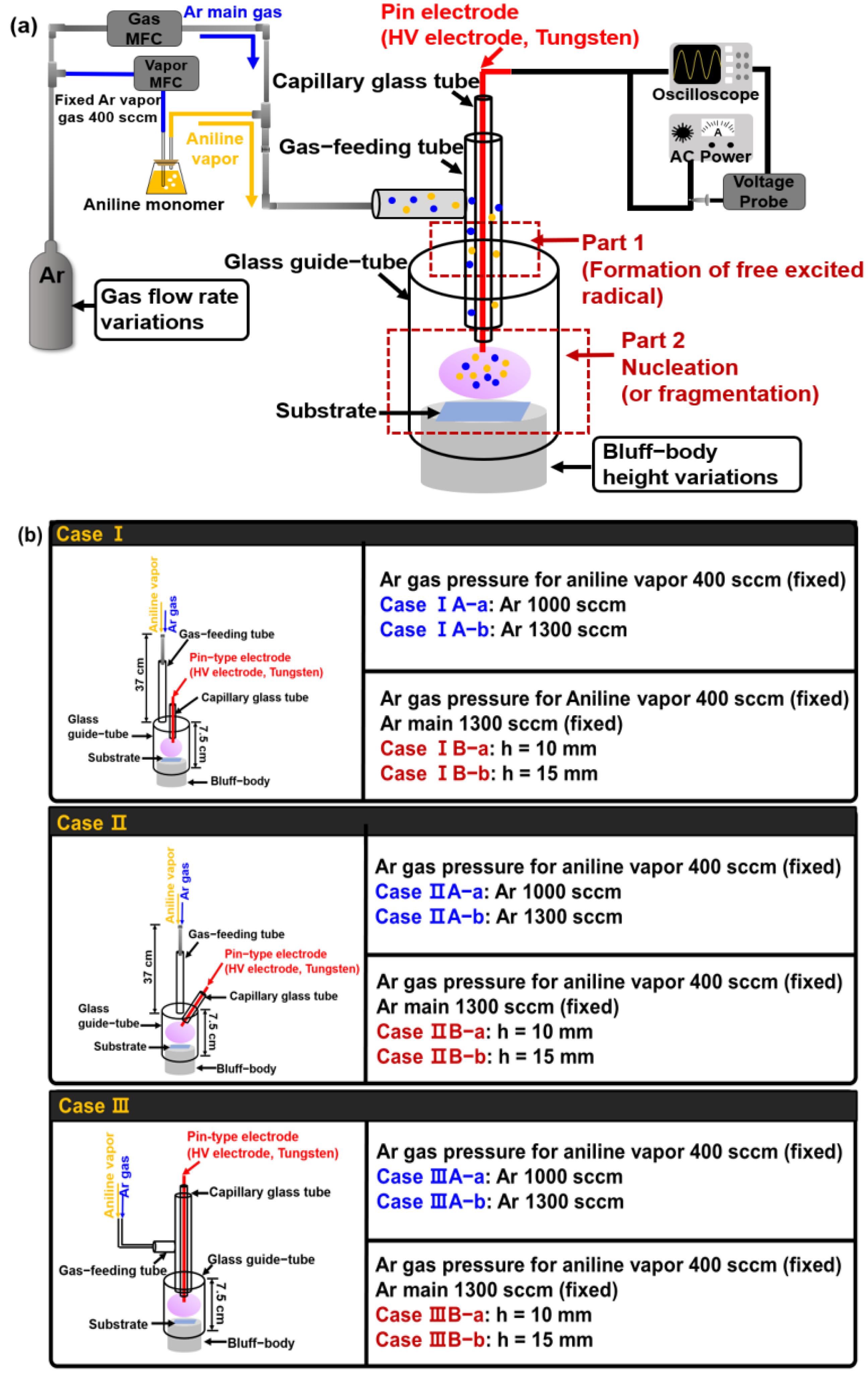
2.1. Experimental Setup
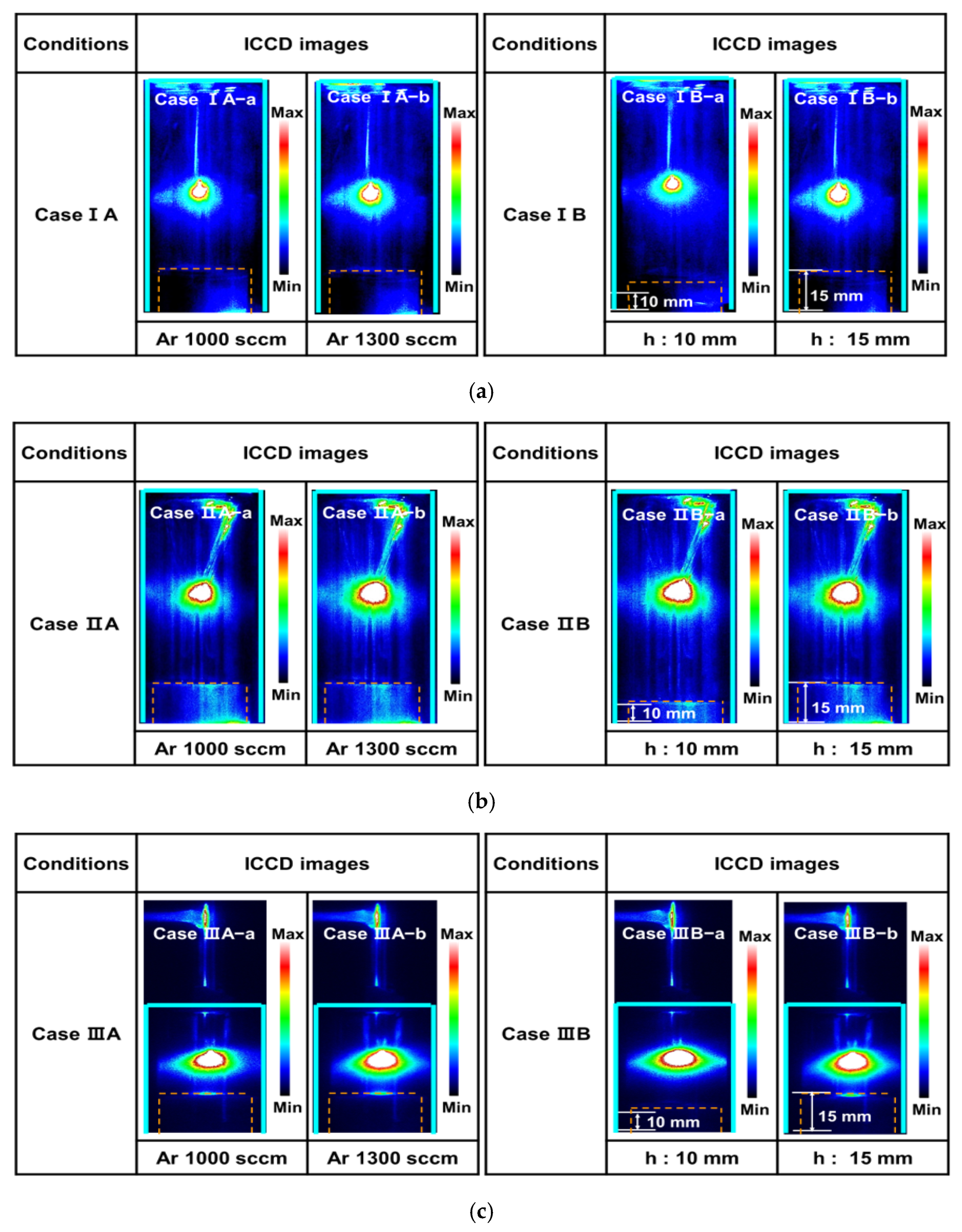
2.2. Intensified Charge-Coupled Device (ICCD)
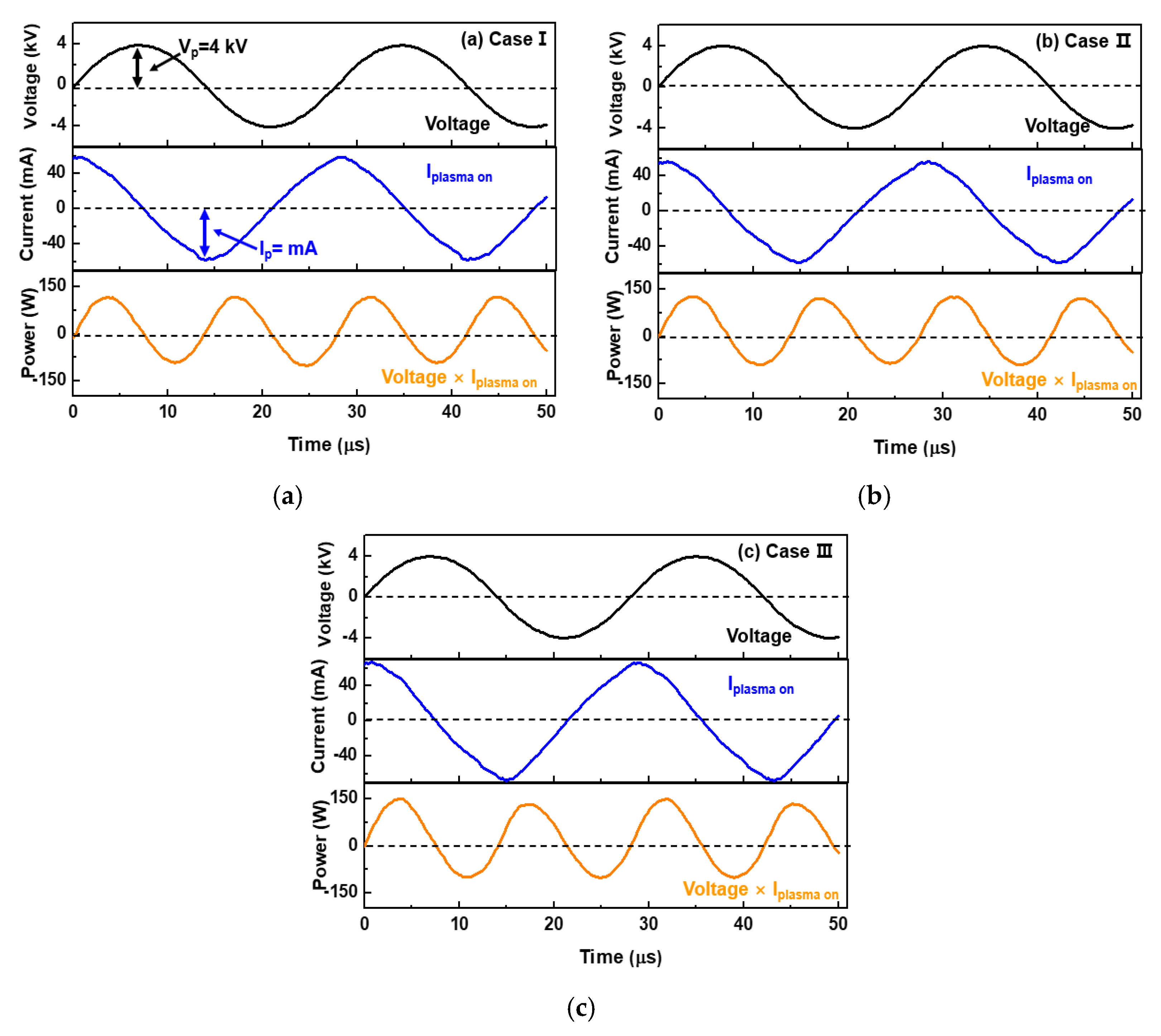
2.3. Discharge Voltage and Current Waveform Analysis
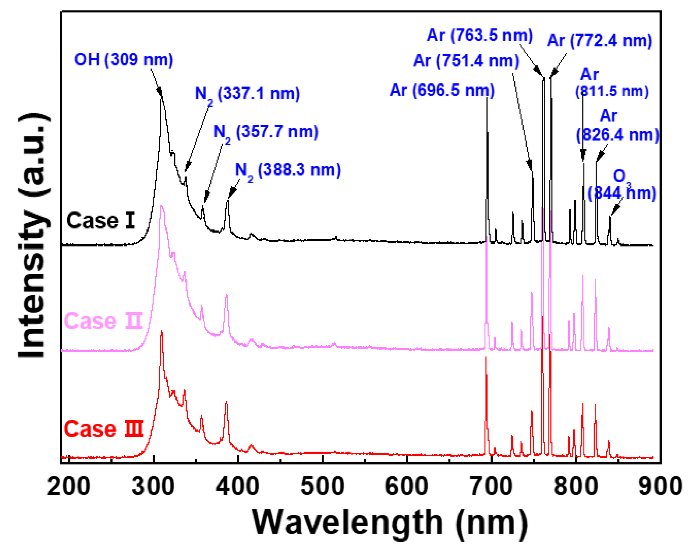
2.4. Optical Emission Spectroscopy
2.5. Field Emission-Scanning Electron Microscopy
2.6. Stylus Profiler
2.7. Atomic Force Microscopy
2.8. Fourier Transform Infrared Spectroscopy
3. Results
4. Conclusions
Author Contributions
Funding
Data Availability Statement
Acknowledgments
Conflicts of Interest
References
- Nur, M.; Kinandana, A.W.; Winarto, P.; Muhlisin, Z.; Nasrudin. Study of an atmospheric pressure plasma jet of argon generated by column dielectric barrier discharge. J. Phys. Conf. Ser. 2016, 776, 012102. [Google Scholar] [CrossRef]
- Chauvet, L.; Therese, L.; Caillier, B.; Guillot, P. Characterization of an asymmetric DBD plasma jet source at atmospheric pressure. J. Anal. At. Spectrom. 2014, 29, 2050–2057. [Google Scholar] [CrossRef]
- Nastuta, A.V.; Gerling, T. Cold atmospheric pressure plasma jet operated in Ar and He: From basic plasma properties to vacuum ultraviolet, electric field and safety thresholds measurements in plasma medicine. Appl. Sci. 2022, 12, 644. [Google Scholar] [CrossRef]
- Deng, S.; Cheng, C.; Ni, G.; Meng, Y.; Chen, H. Bacterial inactivation by atmospheric pressure dielectric barrier discharge plasma jet. Jpn. J. Appl. Phys. 2008, 48, 7009–7012. [Google Scholar] [CrossRef]
- Kuzminova, A.; Kretková, T.; Kylián, O.; Hanuš, J.; Khalakhan, I.; Prukner, V.; Doležalová, E.; Šimek, M.; Biederman, H. Etching of polymers, proteins, and bacterial spores by atmospheric pressure DBD plasma in air. J. Phys. D Appl. Phys. 2017, 50, 135201. [Google Scholar] [CrossRef]
- Dimitrakellis, P.; Travlos, A.; Psycharis, V.P.; Gogolides, E. Superhydrophobic paper by facile and fast atmospheric pressure plasma etching. Plasma Process Polym. 2017, 14, 1600069. [Google Scholar] [CrossRef]
- Prakash, C.V.; Behera, N.; Patel, K.; Kumar, A. Concise characterization of cold atmospheric pressure helium plasma jet. AIP Adv. 2021, 11, 085329. [Google Scholar] [CrossRef]
- Zhou, Y.-J.; Yuan, Q.-H.; Li, F.; Wang, X.-M.; Yin, G.-Q.; Dong, C.-Z. Nonequilibrium atmospheric pressure plasma jet using a combination of 50 kHz/2MHz dual-frequency power sources. Phys. Plasmas 2013, 20, 113502. [Google Scholar] [CrossRef]
- Mohamed, A.-A.H.; Aljuhani, M.M.; Almarashi, J.Q.M.; Alhazime, A.A. The effect of a second grounded electrode on the atmospheric pressure argon plasma jet. Plasma Res. Express 2020, 2, 015011. [Google Scholar] [CrossRef]
- Kang, H.R.; Chung, T.H.; Joh, H.M.; Kim, S.J. Effects of dielectric tube shape and pin-electrode diameter on the plasma plume in atmospheric pressure helium plasma jets. IEEE Trans. Plasma Sci. 2017, 45, 691–697. [Google Scholar] [CrossRef]
- Deepak, G.D.; Joshi, N.K.; Prakash, R. Model analysis and electrical characterization of atmospheric pressure cold plasma jet in pin electrode configuration. AIP Adv. 2018, 8, 055321. [Google Scholar] [CrossRef] [Green Version]
- Lietz, A.M.; Kushner, M.J. Electrode configurations in atmospheric pressure plasma jets: Production of reactive species. Plasma Sources Sci. Technol. 2018, 27, 105020. [Google Scholar] [CrossRef] [Green Version]
- Nguyen, D.B.; Mok, Y.S.; Lee, W.G. Enhanced atmospheric pressure plasma jet performance by an alternative dielectric barrier discharge configuration. IEEE Trans. Plasma Sci. 2019, 47, 4795–4801. [Google Scholar] [CrossRef]
- Lommatzsch, U.; Ihde, J. Plasma polymerization of HMDSO with an atmospheric pressure plasma jet for corrosion protection of aluminum and low-adhesion surfaces. Plasma Processes Polym. 2009, 6, 642–648. [Google Scholar] [CrossRef]
- Jiang, N.; Ji, A.; Cao, Z. Atmospheric pressure plasma jet: Effect of electrode configuration, discharge behavior, and its formation mechanism. J. Appl. Phys. 2009, 106, 013308. [Google Scholar] [CrossRef] [Green Version]
- Park, C.-S.; Kim, D.Y.; Kim, D.H.; Lee, H.-K.; Shin, B.J.; Tae, H.-S. Humidity-independent conducting polyaniline films synthesized using advanced atmospheric pressure plasma polymerization with in-situ iodine doping. Appl. Phys. Lett. 2017, 110, 033502. [Google Scholar] [CrossRef] [Green Version]
- Kim, J.Y.; Iqbal, S.; Jang, H.J.; Jung, E.Y.; Bae, G.T.; Park, C.-S.; Shin, B.J.; Tae, H.-S. Transparent polyaniline thin film synthesized using a low-voltage-driven atmospheric pressure plasma reactor. Materials 2021, 14, 1278. [Google Scholar] [CrossRef]
- Kim, J.Y.; Iqbal, S.; Jang, H.J.; Jung, E.Y.; Bae, G.T.; Park, C.-S.; Tae, H.-S. In-situ iodine doping characteristics of conductive polyaniline film polymerized by low-voltage-driven atmospheric pressure plasma. Polymers 2021, 13, 418. [Google Scholar] [CrossRef]
- Kim, D.H.; Park, C.-S.; Kim, W.H.; Shin, B.J.; Hong, J.G.; Park, T.S.; Seo, J.H.; Tae, T.-S. Influences of guide-tube and bluff-body on advanced atmospheric pressure plasma source for single-crystalline polymer nanoparticle synthesis at low temperature. Phys. Plasmas 2017, 24, 023506. [Google Scholar] [CrossRef] [Green Version]
- Lotfy, K. The impact of the carrier gas composition of non-thermal atmospheric pressure plasma jet for bacteria sterilization. AIP Adv. 2020, 10, 015303. [Google Scholar] [CrossRef]
- Xiao, D.; Cheng, C.; Lan, Y.; Ni, G.H.; Shen, J.; Meng, Y.D.; Chu, P.K. Effects of atmospheric-pressure nonthermal nitrogen and air plasma on bacteria inactivation. IEEE Trans. Plasma Sci. 2016, 44, 2699–2707. [Google Scholar] [CrossRef]
- Bae, G.T.; Park, C.-S.; Jung, E.Y.; Kim, D.; Jang, H.J.; Shin, B.J.; Tae, T.-S. Atmospheric synthesis of polyvinylidene fluoride film using novel atmospheric pressure plasma deposition with direct injection nozzle. Mol. Cryst. Liq. Cryst. 2021, 1972207. [Google Scholar] [CrossRef]
- Zhang, J.; Wang, Y.; Wang, D. Computational simulation of atmospheric pressure discharges with the needle-array electrode. Phys. Plasmas 2018, 25, 072101. [Google Scholar] [CrossRef]
- Liu, T.; Timoshkin, I.; Wilson, M.P.; Given, M.J.; MacGregor, S.J. The nanosecond impulsive breakdown characteristics of air, N2, and CO2 in a sub-mm gap. Plasma 2022, 5, 12–29. [Google Scholar] [CrossRef]
- Liu, D.; Zhang, Z.; Liu, Z.; Wang, B.; Li, Q.; Wang, X.; Kong, M.G. Plasma jets with needle–ring electrodes: The insulated sealing of the needle and its effect on the plasma characteristics. IEEE Trans. Plasma Sci. 2018, 46, 2942–2948. [Google Scholar] [CrossRef]
- Sato, Y.; Ishikawa, K.; Tsutsumi, T.; Ui, A.; Akita, M.; Oka, S.; Hori, M. Numerical simulations of stable, high-electron-density atmospheric pressure argon plasma under pin-to-plane electrode geometry: Effects of applied voltage polarity. J. Phys. D Appl. Phys. 2020, 53, 265204. [Google Scholar] [CrossRef]
- Botewad, S.N.; Pahurkar, V.G.; Muley, G.G. Fabrication and evaluation of evanescent wave absorption based polyaniline-cladding modified fiber optic urea biosensor. Opt. Fiber Technol. 2018, 40, 8–12. [Google Scholar] [CrossRef]
- Wang, S.; Zhou, Y.; Liu, Y.; Wang, L.; Gao, C. Enhanced thermoelectric properties of polyaniline/polypyrrole/carbon nanotube ternary composites by treatment with a secondary dopant using ferric chloride. J. Mater. Chem. C 2020, 8, 528–535. [Google Scholar] [CrossRef]
- Su, N. Improving electrical conductivity, thermal stability, and solubility of polyaniline-polypyrrole nanocomposite by doping with anionic spherical polyelectrolyte brushes. Nanoscale Res. Lett. 2015, 10, 301. [Google Scholar] [CrossRef] [Green Version]


| Electrode Configuration | Case I: Vertically Parallel Pin Electrode |
|---|---|
| Case II: Titled Pin Electrode | |
| Case III: Vertically Combined Pin Electrode | |
| Precursor liquid solution | Aniline monomer |
| Driving power source | AC sinusoidal |
| Plasma driving voltage (V p-p) | 8 kV (Fixed) |
| Frequency | 30 kHz (Fixed) |
| Argon pressure for aniline vapor | 400 sccm (Fixed) |
| Argon main gas pressure | 1000 sccm and 1300 sccm (controllable) |
| Bluff-body height | 10 mm and 15 mm (controllable) |
| Electrode Configuration | Case I | Case II | Case III |
|---|---|---|---|
| Driving type | AC | AC | AC |
| Voltage waveform | Sinusoidal | Sinusoidal | Sinusoidal |
| Plasm a driving voltage (V p-p) | 8 kV | 8 kV | 8 kV |
| Average power | 0.8 W | 1.5 W | 1.6 W |
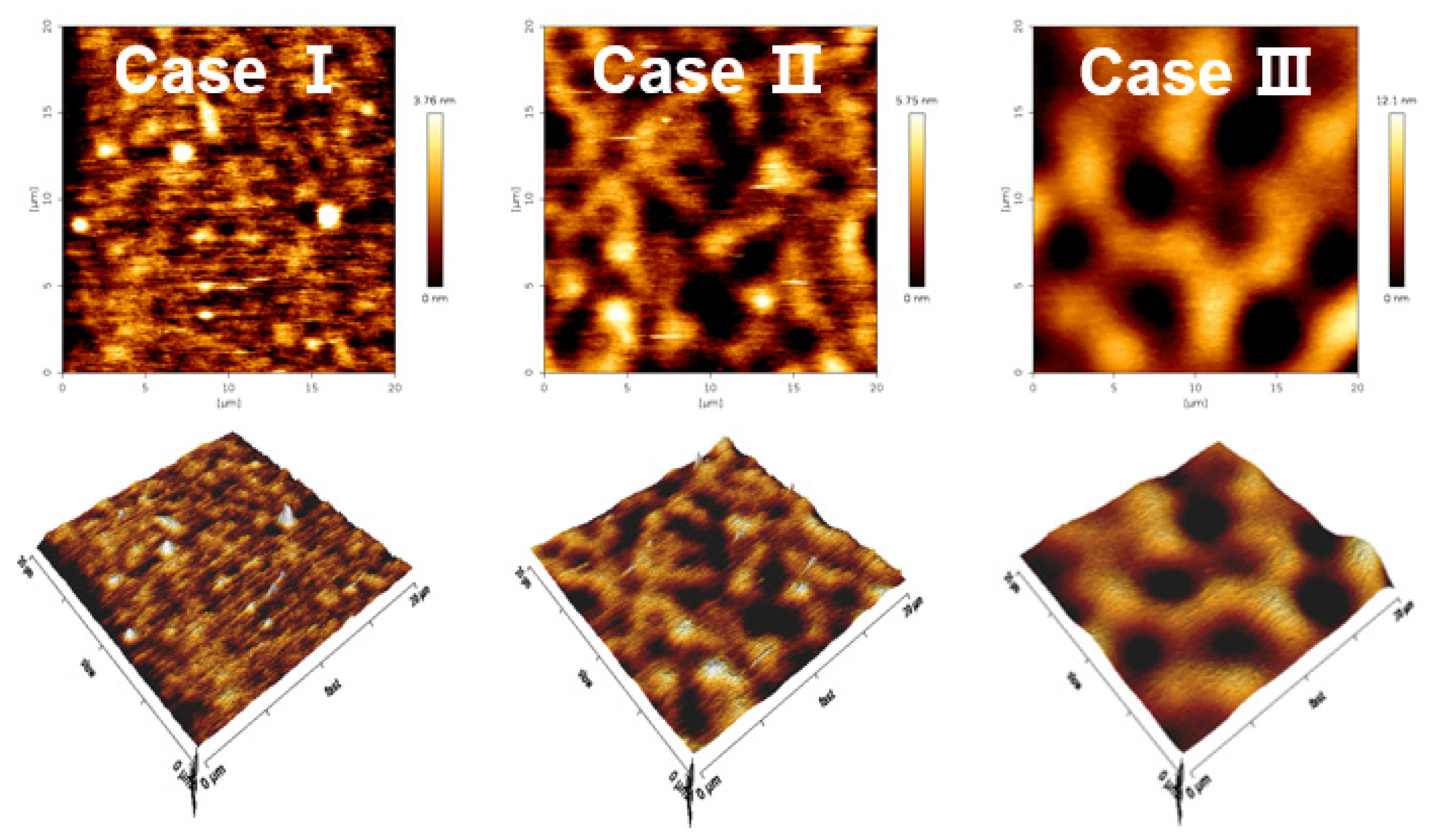
| Sample Conditions | Case I | Case II | Case III |
|---|---|---|---|
| Ra | 2.22 nm | 1.03 nm | 0.61 nm |
| Rrms | 2.75 nm | 1.31 nm | 0.85 nm |
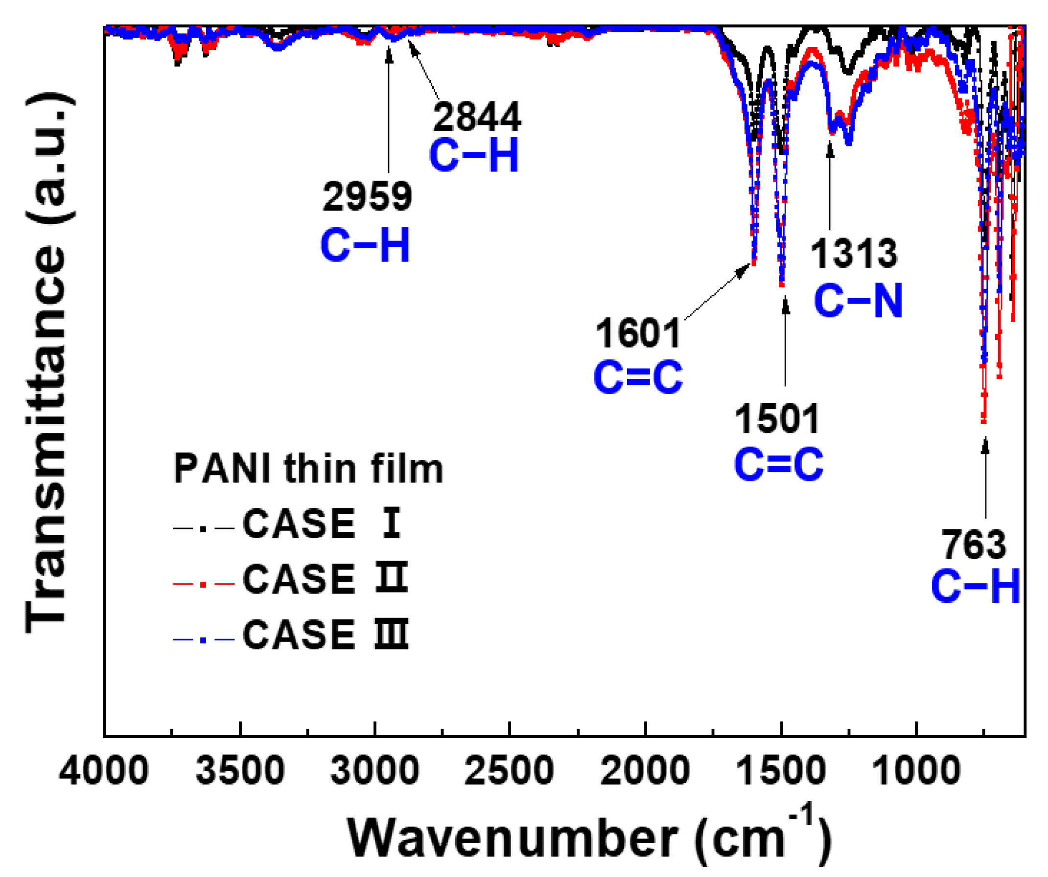
| Wavenumber | Peak Assignment |
|---|---|
| 763 cm−1 | C–H out-of-plane bending |
| 1313 cm−1 | C–N stretching vibration |
| 1501 cm−1 | C=C stretching vibrations of the benzenoid rings |
| 1601 cm−1 | C=C stretching vibrations of quinoid rings |
| 2844 cm−1 | C–H stretching vibration |
| 2959 cm−1 | C–H stretching vibration |
Publisher’s Note: MDPI stays neutral with regard to jurisdictional claims in published maps and institutional affiliations. |
© 2022 by the authors. Licensee MDPI, Basel, Switzerland. This article is an open access article distributed under the terms and conditions of the Creative Commons Attribution (CC BY) license (https://creativecommons.org/licenses/by/4.0/).
Share and Cite
Jung, E.Y.; Park, C.-S.; Jang, H.J.; Iqbal, S.; Hong, T.E.; Shin, B.J.; Choi, M.; Tae, H.-S. Optimization of Atmospheric Pressure Plasma Jet with Single-Pin Electrode Configuration and Its Application in Polyaniline Thin Film Growth. Polymers 2022, 14, 1535. https://doi.org/10.3390/polym14081535
Jung EY, Park C-S, Jang HJ, Iqbal S, Hong TE, Shin BJ, Choi M, Tae H-S. Optimization of Atmospheric Pressure Plasma Jet with Single-Pin Electrode Configuration and Its Application in Polyaniline Thin Film Growth. Polymers. 2022; 14(8):1535. https://doi.org/10.3390/polym14081535
Chicago/Turabian StyleJung, Eun Young, Choon-Sang Park, Hyo Jun Jang, Shahzad Iqbal, Tae Eun Hong, Bhum Jae Shin, Muhan Choi, and Heung-Sik Tae. 2022. "Optimization of Atmospheric Pressure Plasma Jet with Single-Pin Electrode Configuration and Its Application in Polyaniline Thin Film Growth" Polymers 14, no. 8: 1535. https://doi.org/10.3390/polym14081535