
Flexible Electromagnetic Shielding Nano-Composites Based on Silicon and NiFe2O4 Powders
 , ,
, ,
Abstract
:1. Introduction
2. Materials and Preparation Methods
2.1. Materials
- The ferrite powder was synthesized by a simple and innovative co-precipitation route, mixing suitable volumes of 10 mM solution of Fe3+ and 10 mM Ni2+ solution, in order to obtain a molar ratio of 2:1. The solution was titrated with an excess of NaOH at 90 °C, and stirred for 30 min. The obtained precipitate was washed with distilled water three times and dried. In order to increase the crystallinity degree of ferrite powders annealed at 700 °C for 3 h. The average dimension of synthesized particles was about 750 nm. The procedure is much simpler and economical compared to similar ones, co-precipitation with mechanical alloying, or sol–gel auto-combustion, as in [52,53,54], but the respective ones are destinated for achieving particles under 50 nm, very useful for other applications, as permanent magnets. However, in our case, particles with sub-micron dimensions, which are more facile and more economical to obtain, are also ideal for the proposed application and very compatible with the matrix, easy to be dispersed and creates no particle agglomeration, which is a common phenomenon at composites with particles with dimension under 100 nm.
2.2. Equipment
2.2.1. Processing Equipment
2.2.2. Characterization Equipment
- -
- Analytical balance type XS204, precision: 0.1 mg; linearity: ±0.2 mg; density kit for solids and liquids;
- -
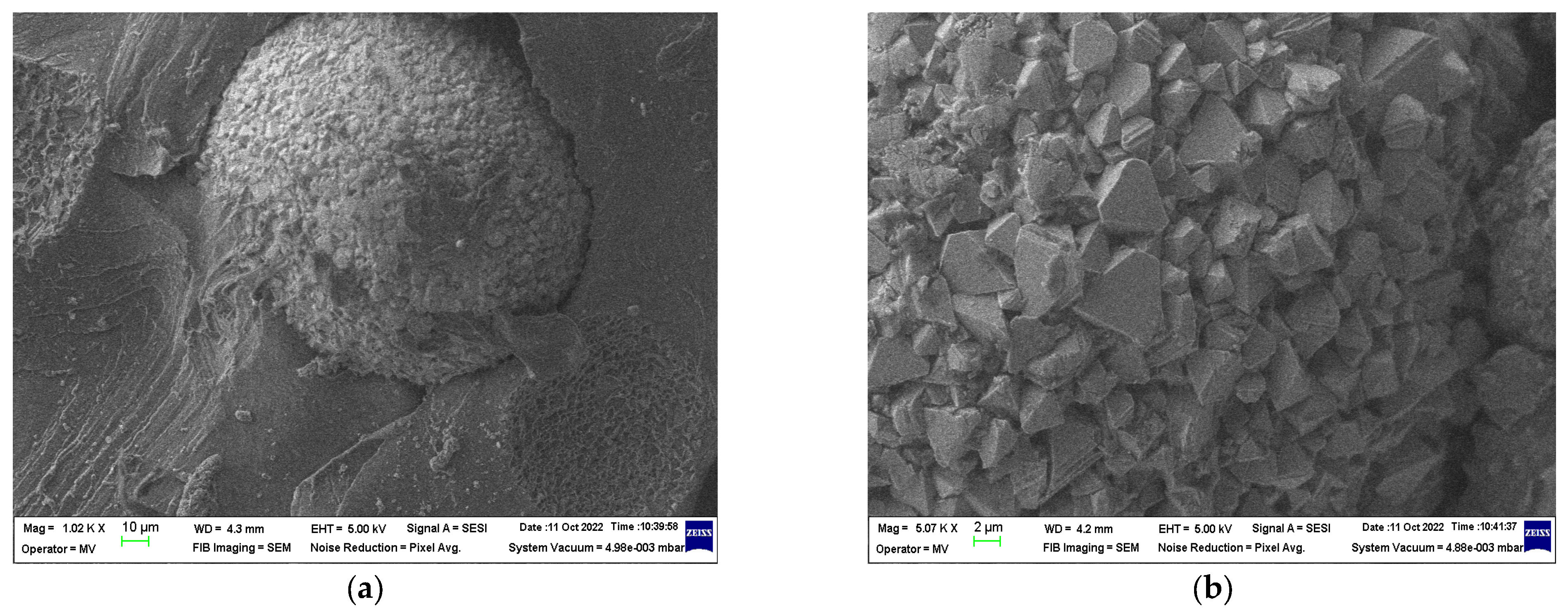
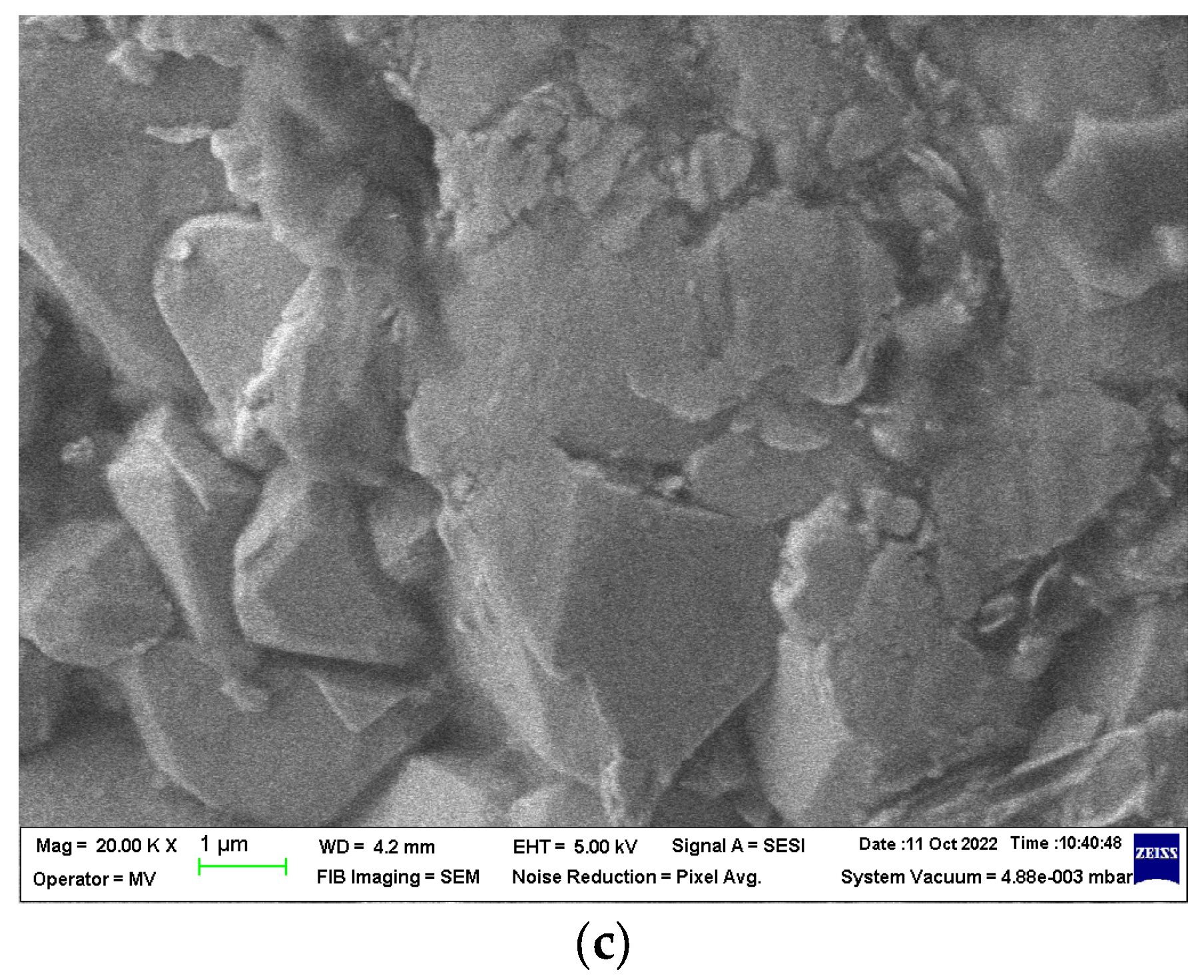
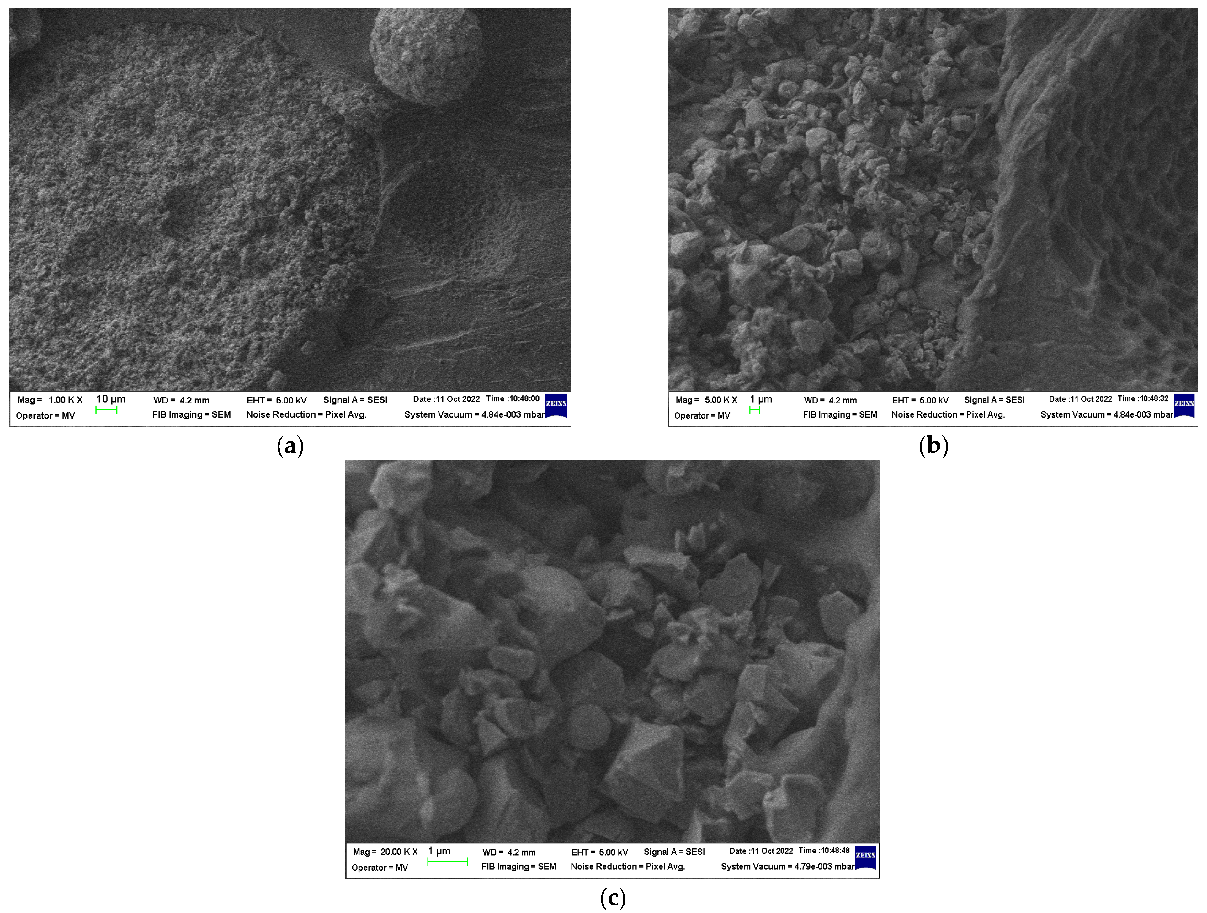
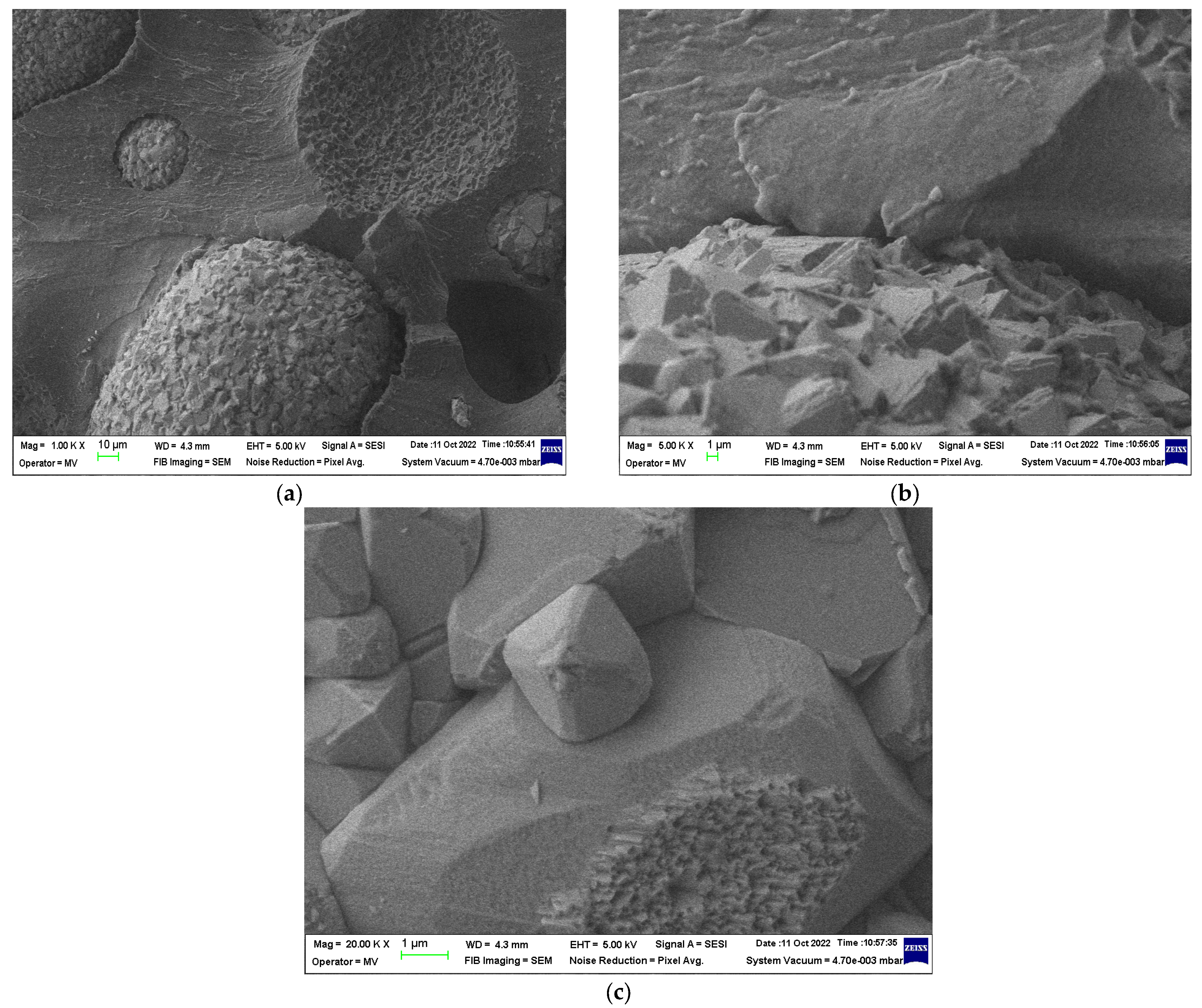
- Scanning electron microscope with field emission source and focused ion beam (SEM)—equipment dedicated to the study of microscopic structures and surfaces of different types of materials. There can be studied: inorganic samples and organic samples: polymers, plastics, polycomposite materials, electrically conductive or non-conductive materials, magnetic materials, as well as materials in compact form, powders, or thin layers. Images were taken at an accelerating voltage of 1 or 2 kV with very close proximity to the objective lens. The detector used was an Everhart Thorn-ley type secondary electron detector with a Faraday cup—resulting in micrographs highlighting the morphology and topography of the analyzed surfaces. The fields recorded in these micrographs are relatively narrow from a few hundred nm to microns, depending on the magnification used. Thus, SEM analyses were performed for all the composite materials obtained, as well as for the ferrite powder used.
- -
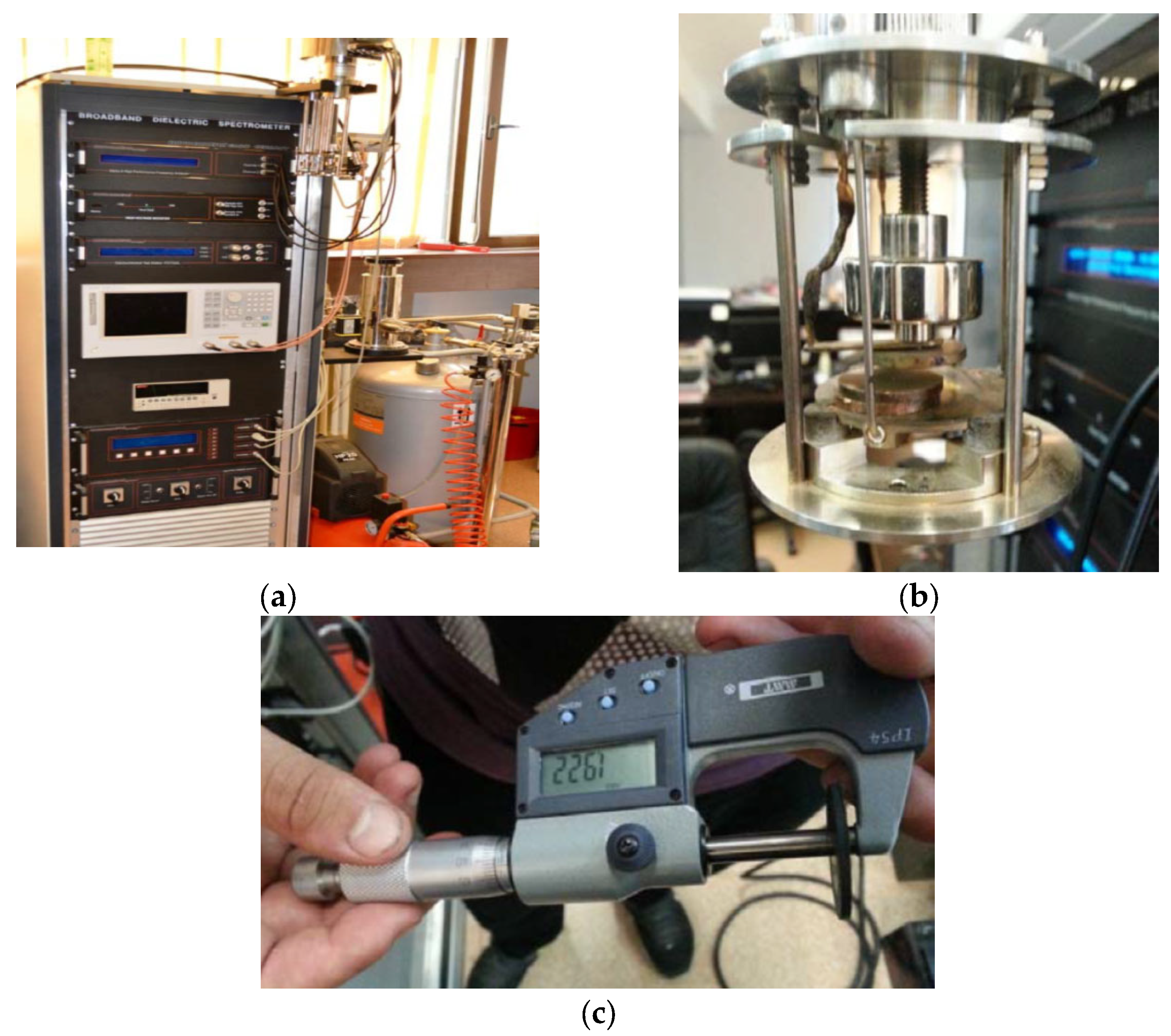
- Dielectric spectroscopy (SOLARTRON Dielectric Spectrometer, Solartron Analytical, Farnborough, UK) and the impedance analyzer type 4294A (Agilent Technology, Santa Clara, CA, USA) and the kit for measuring magnetic properties 16454A;
- -
- Signal Generator Rohde & Schwarz SMCV100B RF (Munich, Germany), min 4kHz, max 3GHz;
- -
- Signal analyzer Rohde & Schwarz FPC1500 Desktop Spectrum Analyser (Munich, Germany), 5 kHz-3 GHz; Coaxial transmission device; Anechoic chamber; Schwartzbeck antennas (Schönau, Germany);
- -
- The TG/DSC thermal analysis of composite plastic materials was performed on a STA 449 F3 Jupiter TG-DSC simultaneous thermal analyzer (NETZSCH, Selb, Germany). This analyzer allows the determination of mass variations and thermal changes for different types of materials.
2.3. Preparation Methods
2.3.1. Obtaining Composite Materials
2.3.2. Characterization of the Obtained Materials
- SEM Structural Analyses were Carried out According to [57]
- Tests to Determine Magnetic Permeability [58]

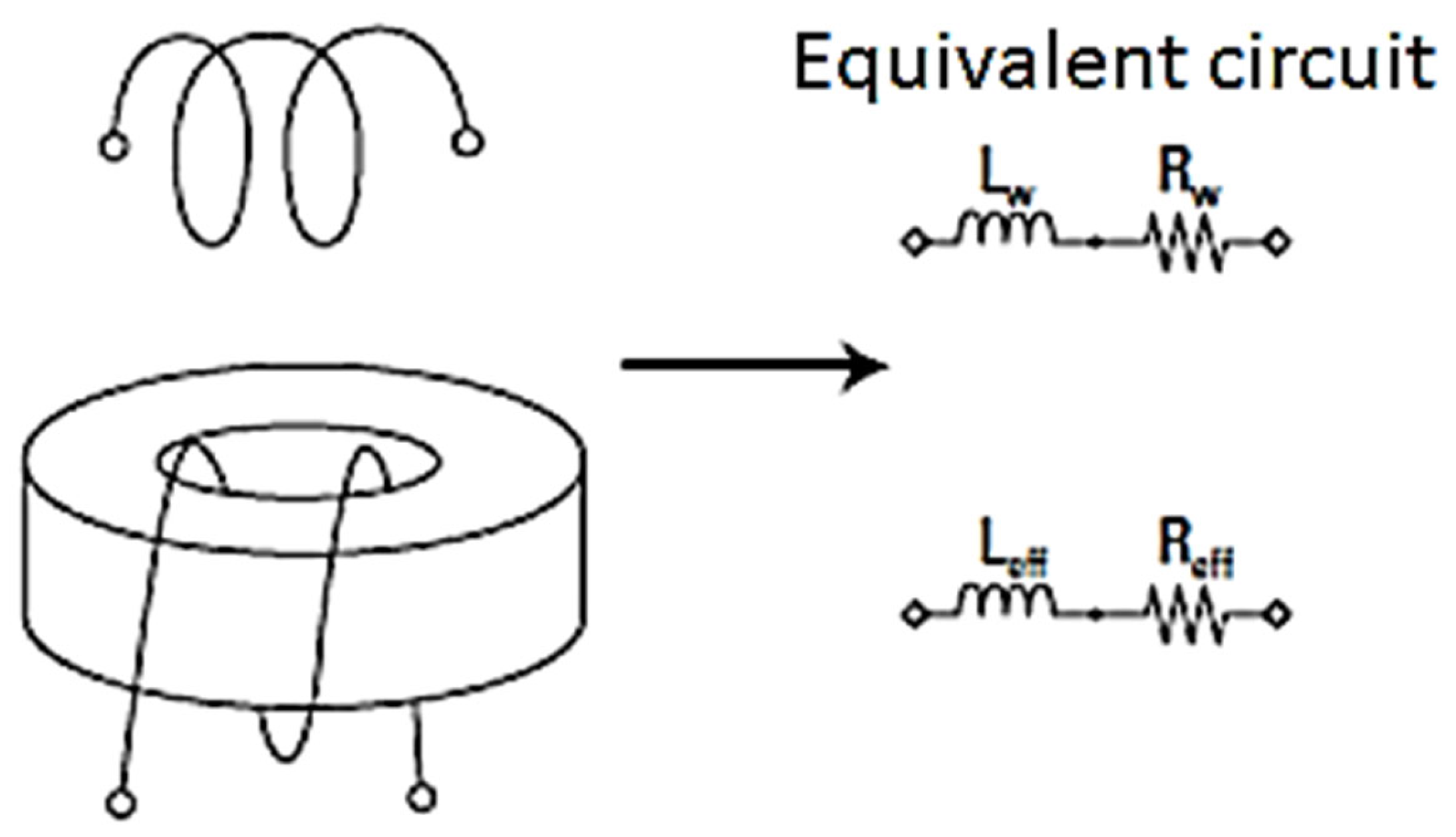
- Reff: the equivalent resistance of the magnetic core losses including the wire resistance;
- Leff: the inductance of the coil;
- N: the number of windings;
- Rw: wire resistance;
- l: average length of the magnetic core;
- A: cross-sectional area of the magnetic core;
- ω = 2πf (f—frequency)
- μ0 = 4π 107 (H/m)
- Features of the measuring device:
- Measured parameters: |Z|, |Y|, R, C, D, Q, ε*; µ*; tgδ
- The measurement frequency: 40 Hz–110 MHz;
- Configuration terminal: 7 mm
- Compensation: open, short, and load
Thermal Analysis—Differential Scanning Calorimetry
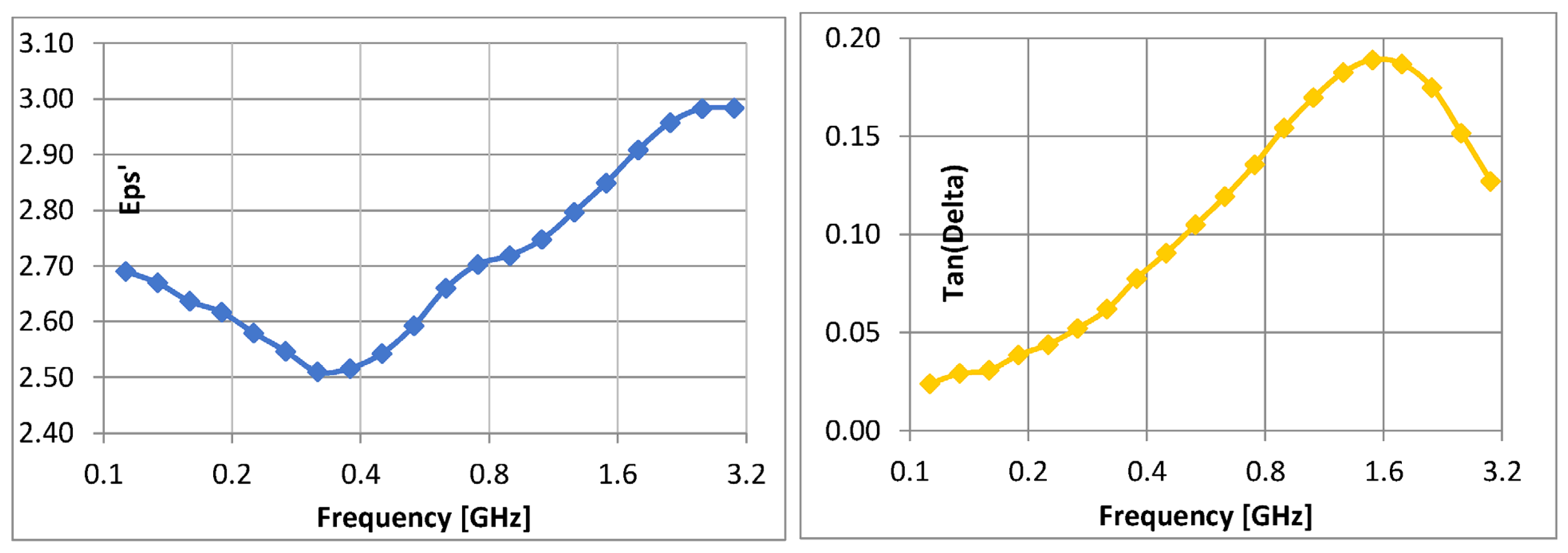
Broadband Dielectric Measurements
3. Results and Discussion
3.1. Determination of Hydrostatic Density
3.2. SEM Structural Analyses
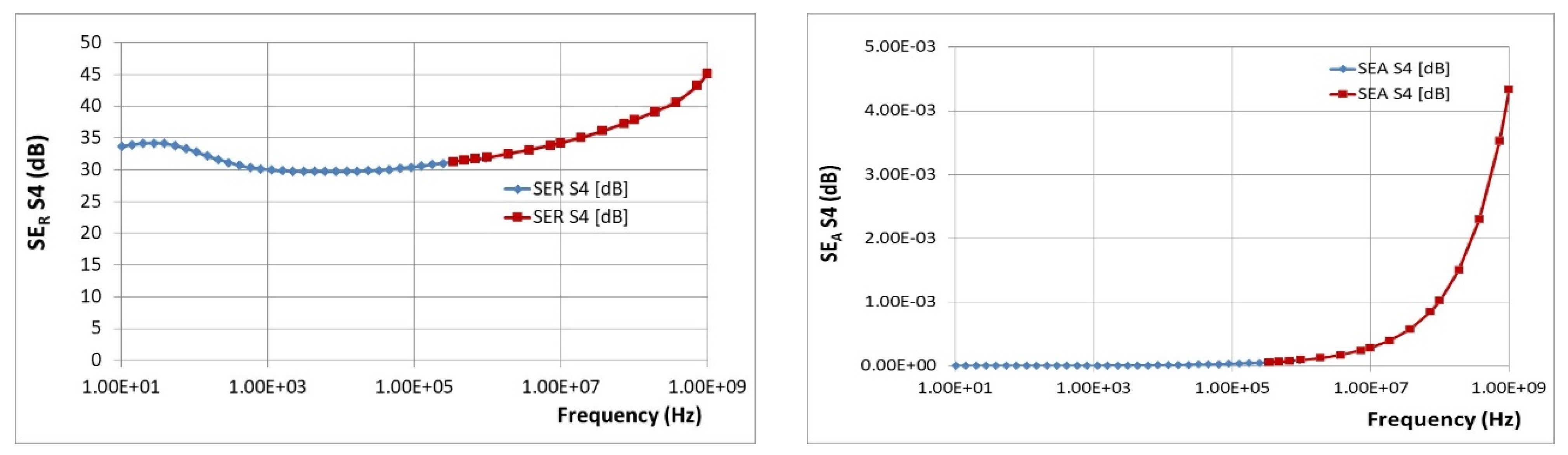
3.3. Electromagnetic Tests
3.3.1. Tests to Determine Magnetic Permeability
3.3.2. Comparative Dielectric Tests
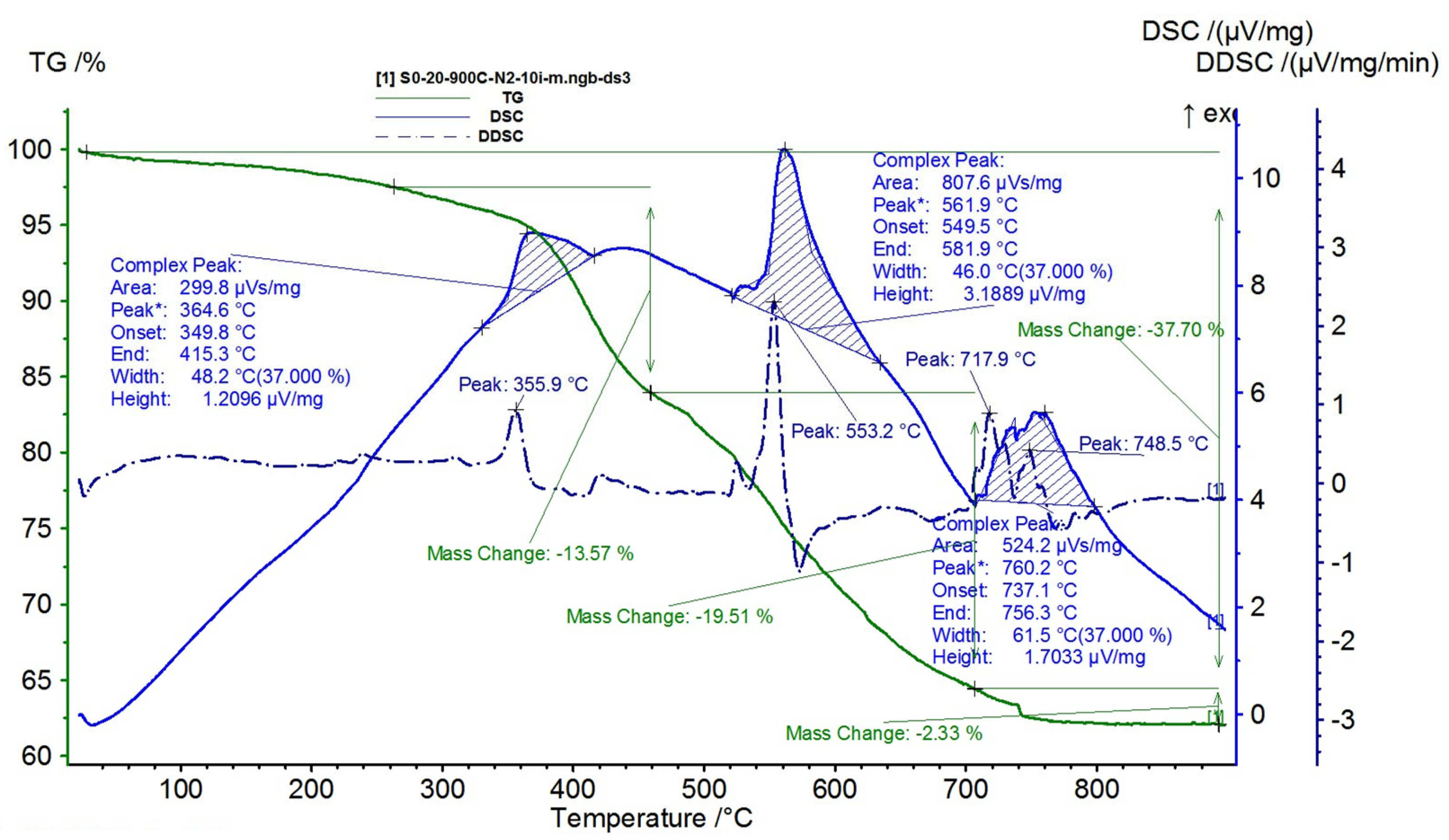
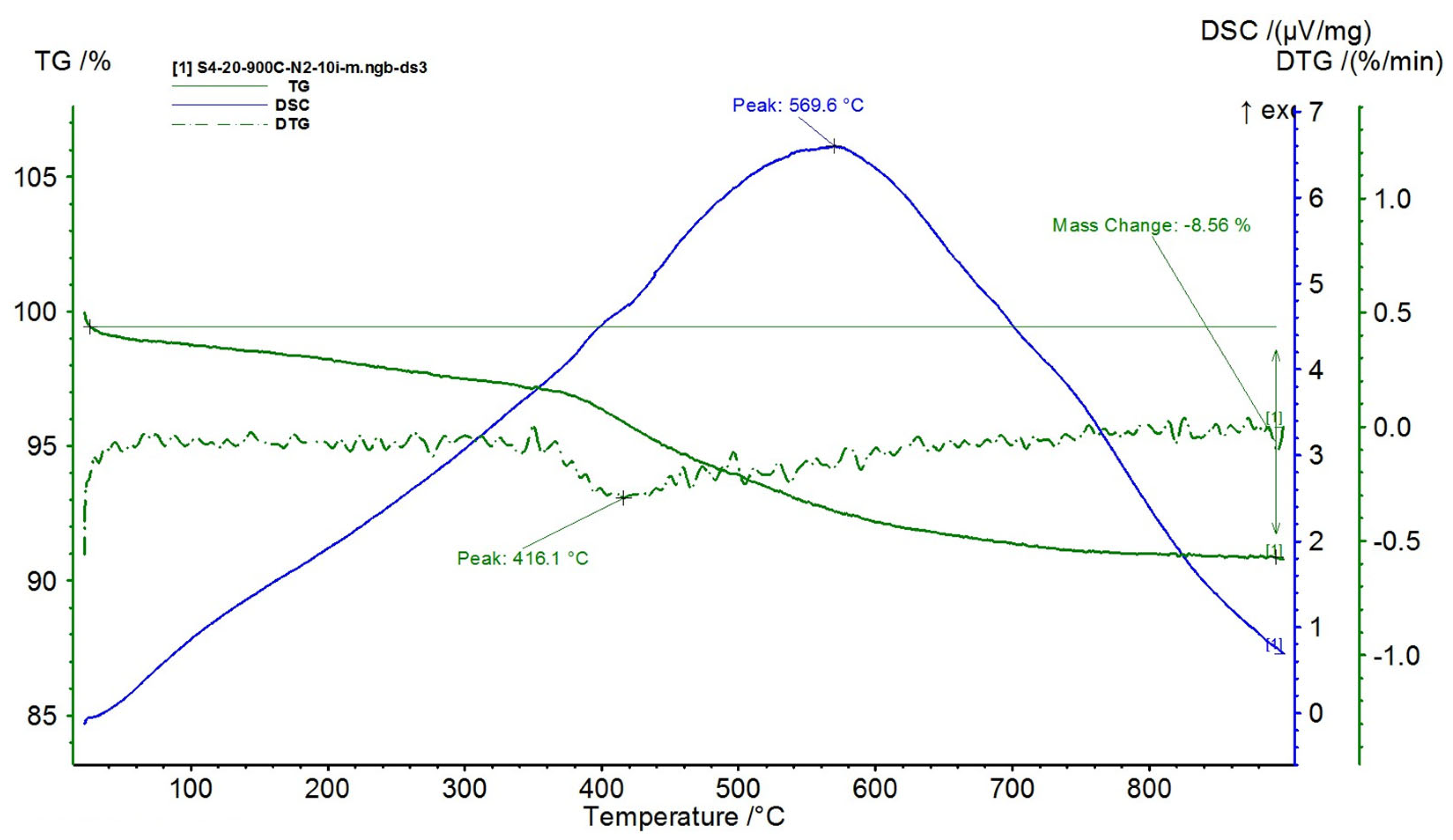
3.4. Thermal Stability
- -
- The first degradation stage takes place at the maximum temperature of 364.6 °C, which corresponds to a mass loss of 13.57%;
- -
- The second degradation stage has a higher intensity and occurs at the maximum temperature of 561.9 °C, corresponding to a mass loss of 19.51%;
- -
- The third degradation stage takes place at the maximum temperature of 760.2 °C and shows a small mass loss of 2.33%.
- -
- The first degradation stage takes place at the maximum temperature of 366.3 °C, which corresponds to a mass loss of 5.82%;
- -
- The second degradation stage occurs at the maximum temperature of 552.4 °C, corresponding to a mass loss of 11.46%;
- -
- The third degradation stage takes place at the maximum temperature of 733.2 °C and presents a mass loss of 2.24%.
- -
- For the composite with 60% NiFe2O4, a decomposition temperature of 522.9 °C was recorded, reaching a total mass loss of 17.84%;
- -
- For the composite with 70% NiFe2O4, a decomposition temperature of 545.3 °C was recorded, reaching a total mass loss of 12.08%;
- -
- For the composite with 80% NiFe2O4, a decomposition temperature of 569.6 °C was recorded, reaching a total mass loss of 8.56%.
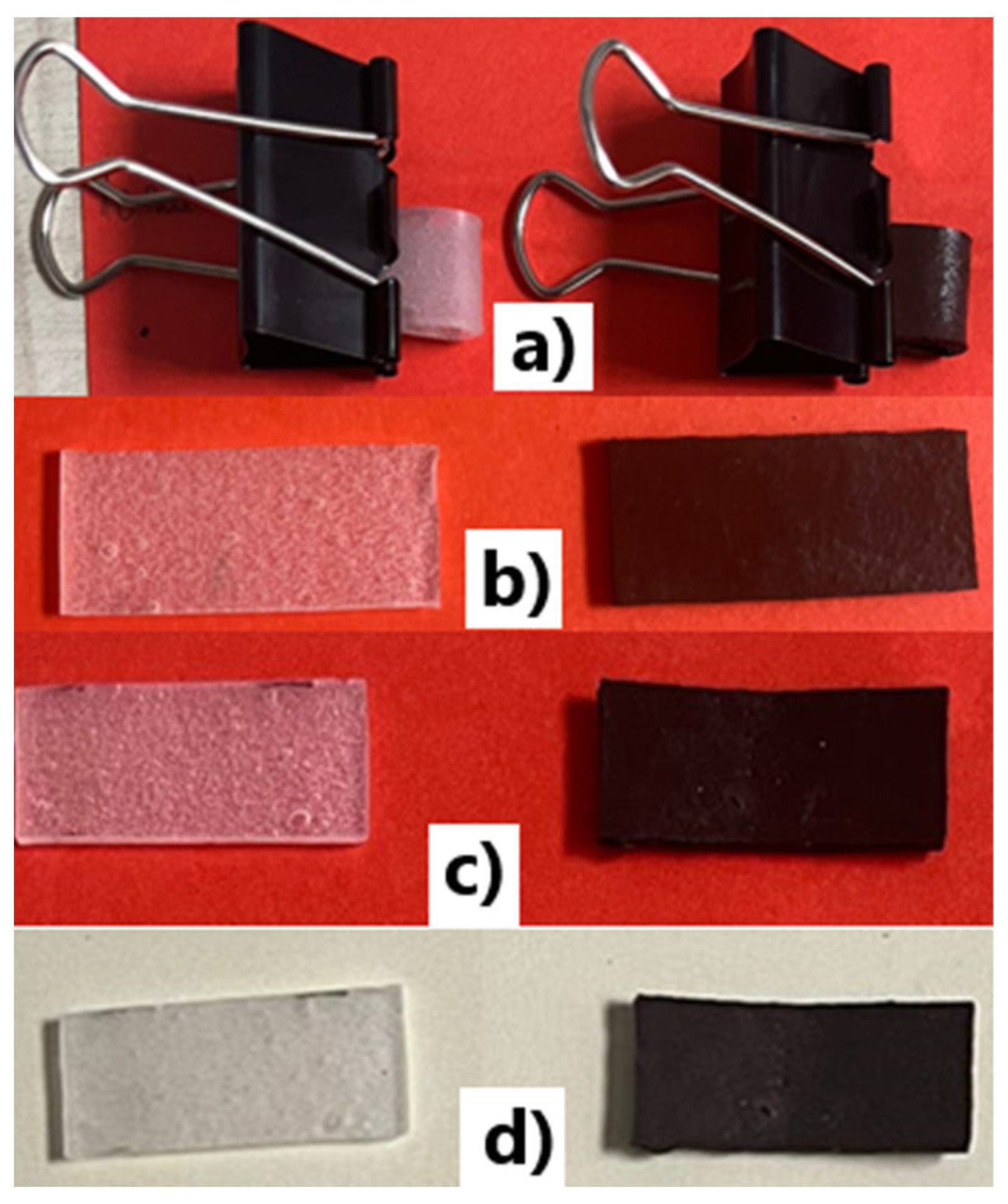
3.5. Flexibility Tests
4. Conclusions
Author Contributions
Funding
Institutional Review Board Statement
Informed Consent Statement
Data Availability Statement
Conflicts of Interest
References
- Stere, E.A.; Popa, I. Alarming Evolutions of Environment and Development for the Future of Mankind. Electroteh. Electron. Autom. EEA 2017, 65, 193–203. [Google Scholar]
- Lingvay, I.; Voina, A.; Lingvay, C.; Mateescu, C. The Impact of the Electromagnetic Pollution of the Environment on the Complex Build-Up Media. Rev. Roum. Sci. Tech. Série Électrotech. Énergétique 2008, 53, 95–111. [Google Scholar]
- Bolte, J.F.; Baliatsas, C.; Eikelboom, T.; van Kamp, I. Everyday exposure to power frequency magnetic fields and associations with non-specific physical symptoms. Environ. Pollut. 2015, 196, 224–229. [Google Scholar] [CrossRef]
- Maslanyj, M.; Simpson, J.; Roman, E.; Schüz, J. Power frequency magnetic fields and risk of childhood leukaemia: Misclassification of exposure from the use of the ‘distance from power line’ exposure surrogate. Bioelectromagnetics 2008, 30, 183–188. [Google Scholar] [CrossRef] [PubMed]
- Baliatsas, C.; Van Kamp, I.; Kelfkens, G.; Schipper, M.; Bolte, J.; Yzermans, J.; Lebret, E. Non-specific physical symptoms in relation to actual and perceived proximity to mobile phone base stations and powerlines. BMC Public Health 2011, 11, 421. [Google Scholar] [CrossRef]
- Baliatsas, C.; Van Kamp, I.; Bolte, J.; Schipper, M.; Yzermans, J.; Lebret, E. Non-Specific Physical Symptoms and Electromagnetic Field Exposure In The General Population: Can We Get More Specific? A Systematic Review. Environ. Int. 2012, 41, 15–28. [Google Scholar] [CrossRef]
- Szemerszky, R.; Zelena, D.; Barna, I.; Bárdos, G. Stress-related endocrinological and psychopathological effects of short- and long-term 50Hz electromagnetic field exposure in rats. Brain Res. Bull. 2010, 81, 92–99. [Google Scholar] [CrossRef]
- Radu, E.; Lipcinski, D.; Tănase, N.; Lingvay, I. The Influence Of The 50 Hz Electric Field On The Development And Maturation Of Aspergillus Niger. Electroteh. Electron. Autom. EEA 2015, 63, 68–74. [Google Scholar]
- Stancu, C.; Lingvay, M.; Szatmari, I.; Lingvay, I. Influence Of 50 Hz Electromagnetic Field on the Yeast (Saccharomyces Cerevisiae) Metabolism. In Proceedings of the 8th International Symposium on Advanced Topics In Electrical Engineering, Bucharest, Romania, 23–25 May 2013. [Google Scholar] [CrossRef]
- Caramitu, A.; Butoi, N.; Rus, T.; Luchian, A.M.; Mitrea, S. The Resistance to the Action of Molds of Some Painting Materials Aged by Thermal Cycling and Exposed to an Electrical Field of 50 Hz. Mater. Plast. 2017, 54, 331–337. [Google Scholar] [CrossRef]
- Lingvay, M.; Caramitu, A.-R.; Bors, A.M.; Lingvay, I.; Sa, S.U.I. Dielectric spectroscopic evaluation in the extremely low frequency range of an Aspergillus niger culture. Stud. UBB Chem. 2019, 64, 279–288. [Google Scholar] [CrossRef]
- Sandu, D.; Lingvay, I.; Lányi, S.; Micu, D.D.; Popescu, C.L.; Brem, J.; Bencze, L.C.; Paizs, C. The Effect Of Electromagnetic Fields On Baker’s Yeast Population Dynamics, Biocatalytic Activity And Selectivity. Stud. Univ. Babes-Bolyai Chem. 2009, 4, 195–201. [Google Scholar]
- Bartha, C.; Caramitu, A.; Jipa, M.; Ignat, D.M.; Tókos, A. Dielectric Behavior Of Sludge From Wastewater Treatment. Stud. UBB Chem. 2020, 65, 85–93. [Google Scholar] [CrossRef]
- Tokos, A.; Bartha, C.; Jipa, M.; Micu, D.-D.; Caramitu, A.-R.; Lingvay, I. Interactions Of Extremely Low-Frequency Electric Field With The Active Sludge Live Materia From Wastewater Treatments. In Proceedings of the 12th International Symposium On Advanced Topics In Electrical Engineering (Atee), Bucharest, Romania, 25–27 March 2021. [Google Scholar] [CrossRef]
- Geetha, S.; Kumar, K.K.S.; Rao, C.R.K.; Vijayan, M.; Trivedi, D.C.K. EMI shielding: Methods and materials—A review. J. Appl. Polym. Sci. 2009, 112, 2073–2086. [Google Scholar] [CrossRef]
- Joshi, M.; Bansala, T.; Mukhopadhyay, S. Innovations in polymer nanocomposite coatings for EMI Shielding applications. IOP Conf. Ser. Mater. Sci. Eng. 2018, 460, 012012. [Google Scholar] [CrossRef]
- Yang, J.; Liao, X.; Li, J.; He, G.; Zhang, Y.; Tang, W.; Wang, G.; Li, G. Light-weight and flexible silicone rubber/MWCNTs/Fe3O4 nanocomposite foams for efficient electromagnetic interference shielding and microwave absorption. Compos. Sci. Technol. 2019, 181, 107670. [Google Scholar] [CrossRef]
- Yu, W.-C.; Wang, T.; Liu, Y.-H.; Wang, Z.-G.; Xu, L.; Tang, J.-H.; Dai, K.; Duan, H.-J.; Xu, J.-Z.; Li, Z.-M. Superior and highly absorbed electromagnetic interference shielding performance achieved by designing the reflection-absorption-integrated shielding compartment with conductive wall and lossy core. Chem. Eng. J. 2020, 393, 124644. [Google Scholar]
- Zhang, Y.; Wang, L.; Zhang, J.; Song, P.; Xiao, Z.; Liang, C.; Qiu, H.; Kong, J.; Gu, J. Fabrication and investigation on the ultra-thin and flexible Ti3C2Tx/co-doped polyaniline electromagnetic interference shielding composite films. Compos. Sci. Technol. 2019, 183, 107833. [Google Scholar] [CrossRef]
- Yang, J.; Liao, X.; Wang, G.; Chen, J.; Tang, W.; Wang, T.; Li, G. Fabrication of a lightweight and flexible silicone rubber foams with ultra-efficient electromagnetic interference shielding and adjustable low reflectivity. J. Mater. Chem. C 2020, 8, 147–157. [Google Scholar]
- Chen, J.; Liao, X.; Xiao, W.; Yang, J.; Jiang, Q.; Li, G. Facile and Green Method To Structure Ultralow-Threshold and Lightweight Polystyrene/MWCNT Composites with Segregated Conductive Networks for Efficient Electromagnetic Interference Shielding. ACS Sustain. Chem. Eng. 2019, 7, 9904–9915. [Google Scholar] [CrossRef]
- Zhang, Z.; Liu, M.; Ibrahim, M.M.; Wu, H.; Wu, Y.; Li, Y.; Mersal, G.A.; El Azab, I.H.; El-Bahy, S.M.; Huang, M.; et al. Flexible polystyrene/graphene composites with epsilon-near-zero properties. Adv. Compos. Hybrid Mater. 2022, 5, 1054–1066. [Google Scholar] [CrossRef]
- Guohua, F.; Zhongyang, W.; Kai, S.; Yao, L.; Runhua, F. Doped ceramics of indium oxides for negative permittivity materials in MHz-kHz frequency regions. J. Mater. Sci. Technol. 2021, 61, 125–131. [Google Scholar]
- Beomsu, S.; Subhadip, M.; Minkyu, L.; Suhyun, K.; Yang-Il, H.; Changwoon, N. Flexible thermoplastic polyurethane-carbon nanotube composites for electromagnetic interference shielding and thermal management. Chem. Eng. J. 2021, 418, 129282. [Google Scholar]
- Kruželák, J.; Kvasničáková, A.; Hložeková, K.; Dosoudil, R.; Gořalík, M.; Hudec, I. Electromagnetic Interference Shielding and Physical-Mechanical Characteristics of Rubber Composites Filled with Manganese-Zinc Ferrite and Carbon Black. Polymers 2021, 13, 616. [Google Scholar] [CrossRef] [PubMed]
- Nguyen, T.; Cao, H.; Do Le Viet, H.; Nguyen, P.; Tran, T.; Phan, T.; Seiichi, K.; Toshiaki, O. Preparation of Electromagnetic Shielding Coating Based on Natural Rubber. Mater. Trans. 2020, 61, 1544–1549. [Google Scholar]
- Kruželák, J.; Kvasničáková, A.; Džuganová, M.; Hašková, L.; Dosoudil, R.; Hudec, I. Curing, Properties and EMI Absorption Shielding of Rubber Composites Based on Ferrites and Carbon Fibres. Polymers 2023, 15, 857. [Google Scholar] [CrossRef]
- Dhawan, S.K.; Anil, O.; Kuldeep, S. Designing of Nano Composites of Conducting Polymers for EMI Shielding. In Advances in Nanocomposites—Synthesis, Characterization and Industrial Applications; Reddy, B., Ed.; InTech Open: Rijeka, Croatia, 2011; ISBN 978-953-307-165-7. [Google Scholar] [CrossRef]
- Fiske, T.J.; Gokturk, H.S.; Kalyon, D. Percolation in magnetic composites. J. Mater. Sci. 1997, 32, 5551–5560. [Google Scholar] [CrossRef]
- Gokturk, H.S.; Fiske, T.J.; Kalyon, M. Percolation in magnetic composites. IEEE Trans. Mag. 1993, 29, 4170. [Google Scholar] [CrossRef]
- Al-Saleh, M.H. Influence of conductive network structure on the EMI shielding and electrical percolation of carbon nanotube/polymer nanocomposites. Synth. Met. 2015, 205, 78–84. [Google Scholar] [CrossRef]
- Fan, X.; Wang, F.; Gao, Q.; Zhang, Y.; Huang, F.; Xiao, R.; Qin, J.; Zhang, H.; Shi, X.; Zhang, G. Nature inspired hierarchical structures in nano-cellular epoxy/graphene-Fe3O4 nanocomposites with ultra-efficient EMI and robust mechanical strength. J. Mater. Sci. Technol. 2021, 103, 177–185. [Google Scholar] [CrossRef]
- Wang, Y.; Liu, R.; Zhang, J.; Miao, M.; Feng, X. Vulcanization of Ti3C2Tx MXene/natural rubber composite films for enhanced electromagnetic interference shielding. Appl. Surf. Sci. 2021, 546, 149143. [Google Scholar] [CrossRef]
- Wang, M.; Tang, X.; Cai, J.; Wu, H.; Shen, J.; Guo, S. Fabrication, mechanisms and perspectives of conductive polymer composites with multiple interfaces for electromagnetic interference shielding: A review. Carbon 2021, 177, 377–402. [Google Scholar] [CrossRef]
- Ren, W.; Yang, Y.; Yang, J.; Duan, H.; Zhao, G.; Liu, Y. Multifunctional and corrosion resistant poly (phenylene sulfide)/Ag composites for electromagnetic interference shielding. Chem. Eng. J. 2021, 415, 129052. [Google Scholar] [CrossRef]
- Fu, B.; Ren, P.; Guo, Z.; Du, Y.; Jin, Y.; Sun, Z.; Dai, Z.; Ren, F. Construction of three-dimensional interconnected graphene nanosheet network in thermoplastic polyurethane with highly efficient electromagnetic interference shielding. Compos. Part B Eng. 2021, 215, 108813. [Google Scholar] [CrossRef]
- Bors, A.M.; Lingvay, D.; Caramitu, A.R.; Iordache, I.; Lingvay, I. Comparative Studies on the Electrical and Mechanical Behavior of Some Soldering and/or Impregnation Lacquers. Mater. Plast. 2019, 56, 129. [Google Scholar] [CrossRef]
- Lingvay, I.; Stancu, C.; Et, A. Studies Concerning the Fast Ageing By Thermal Cycling Of Power Cables. In Proceedings of the 7th International Symposium on Advanced Topics In Electrical Engineering, (Atee), Bucharest, Romania, 12–14 May 2011; pp. 437–440. [Google Scholar]
- Borș, A.; Butoi, N.; Caramitu, A.; Marinescu, V.; Lingvay, I. The thermo-oxidation and resistance to molds action of some polyethylene sorts used at anticorrosive insulation of the underground pipelines. Mat. Plast. 2017, 54, 447–452. [Google Scholar] [CrossRef]
- Rus, T.; Bors, A.M.; Caramitu, A.R.; Lingvay, I.; Vaireanu, D.I. Comparative Studies on the Thermal Ageing of Some Painting Materials. Mater. Plast. 2018, 55, 168–175. [Google Scholar] [CrossRef]
- Rus, T.; Radu, E.; Lingvay, I.; Lingvay, M.; Cioboteabarbu, O.C.; Campureanu, C.; Benga, F.M.; Lazar, G.C.; Vaireanu, D.I. Resistance to the action of filamentous fungi upon some coatings materials. UPB Sci. Bull. Ser. B 2018, 79, 167–180. [Google Scholar]
- Rus, T.; Lingvay, I.; Caramitu, A.R.; Bors, A.M.; Vaireanu, D.I. Comparative Studies on the UV Radiations Resistance of Some Painting Materials. Mater. Plast. 2017, 54, 720–725. [Google Scholar] [CrossRef]
- Bors, A.M.; Caramitu, A.-R.; Marin, D.; Lingvay, I. The Hydrophily of Some Lacquers for Electrical Use. Mater. Plast. 2020, 57, 122–132. [Google Scholar] [CrossRef]
- Caramitu, A.-R.; Mitrea, S.; Marinescu, V.; Ursan, G.-A.; Aradoaie, M.; Lingvay, I. Dielectric Behavior and Morphostructural Characteristics of Some HDPE Composites/Metal Nanopowders. Mater. Plast. 2019, 56, 103–109. [Google Scholar] [CrossRef]
- Hema, S.; Sambhudevan, S. Ferrite-based polymer nanocomposites as shielding materials: A review. Chem. Pap. 2021, 75, 3697–3710. [Google Scholar] [CrossRef]
- Shabzendedar, S.; Modarresi-Alam, A.R.; Noroozifar, M.; Kerman, K. Core-shell nanocomposite of superparamagnetic Fe3O4 nanoparticles with poly(m-aminobenzenesulfonic acid) for polymer solar cells. Org. Electron. 2019, 77, 105462. [Google Scholar] [CrossRef]
- Kalia, S.; Kango, S.; Kumar, A.; Haldorai, Y.; Kumari, B.; Kumar, R. Magnetic polymer nanocomposites for environmental and biomedical applications. Colloid Polym. Sci. 2014, 292, 2025–2052. [Google Scholar] [CrossRef]
- Raheem, A.A. Preparation Of Composite Materials Of Silicon Rubber Reinforced By (Crmnxni1-Xfeo4) For Microwave Absorption At X-Band. Int. J. Eng. Res. Technol. 2018, 11, 273–285. [Google Scholar]
- Hemeda, O.M.; Henaish, A.M.A.; Salem, B.I.; El-Sbakhy, F.S.; Hamad, M.A. The dielectric and magnetic properties of RTV-silicon rubber Ni–Cr ferrite composites. Appl. Phys. A 2020, 126, 121. [Google Scholar] [CrossRef]
- Sankar, S.; Radhu, K.; Wilson, L.; Sreedha, S.; Balakrishnan, S.; Anshida, M.; Nandakumar, K. Magnetic and dielectric properties of nickel-ferrite-embedded natural rubber composites. Polym. Bull. 2018, 75, 5217–5234. [Google Scholar]
- Product Catalogue: HT 45. Available online: https://btools.ro/shop/Silicon-Aditie-RTV2-HT45 (accessed on 2 May 2023).
- Shi, Y.; Ding, J.; Liu, X.; Wang, J. NiFe2O4 ultrafine particles prepared by co-precipitation/mechanical alloying. J. Magn. Magn. Mater. 1999, 205, 249–254. [Google Scholar] [CrossRef]
- Sivakumar, P.; Ramesh, R.; Ramanand, A.; Ponnusamy, S.; Muthamizhchelvan, C. Preparation and properties of nickel ferrite (NiFe2O4) nanoparticles via sol–gel auto-combustion method. Mater. Res. Bull. 2011, 46, 2204–2207. [Google Scholar] [CrossRef]
- Seema, J.; Manoj, K.; Sandeep, C.; Geetika, S.; Mukesh, J.; Singh, V. Structural, magnetic, dielectric and optical properties of nickel ferrite nanoparticles synthesized by co-precipitation method. J. Mol. Struct. 2014, 1076, 55–62. [Google Scholar]
- BS EN ISO 3369:2010; Impermeable Sintered Metal Materials and Hardmetals. Determination of Density. Available online: https://www.en-standard.eu/bs-en-iso-3369-2010-impermeable-sintered-metal-materials-and-hardmetals-determination-of-density/ (accessed on 2 May 2023).
- Bowman, H.A.; Schoonover, R.M. Procedure for High Precision Density Determinations by Hydrostatic Weighing. J. Res. Natl. Bur. Stand. C. Eng. Instrum. 1967, 71, 3. Available online: https://nvlpubs.nist.gov/nistpubs/jres/71C/jresv71Cn3p179_A1b.pdf (accessed on 2 May 2023). [CrossRef]
- Scanning Electron Microscopy. Elemental Analysis and Imaging with X-rays; pp. 365–403, e-book; ISBN 978-3-662-13562-4. Available online: https://link.springer.com/chapter/10.1007/978-3-662-13562-4_9 (accessed on 2 May 2023).
- Simu, C.; Marza, E. Propagation of Electromagnetic Waves. In Radio Antennas; University Horizons Publishing House: Timisoara, Romania, 2001; Available online: https://www.researchgate.net/publication/318494656 (accessed on 2 May 2023).
- ASTME 794:2006; Standard Test Method for Melting and Crystallization Temperatures by Thermal Analysis. Available online: https://global.ihs.com/doc_detail.cfm?document_name=ASTM%20E794&item_s_key=00020307 (accessed on 2 May 2023).
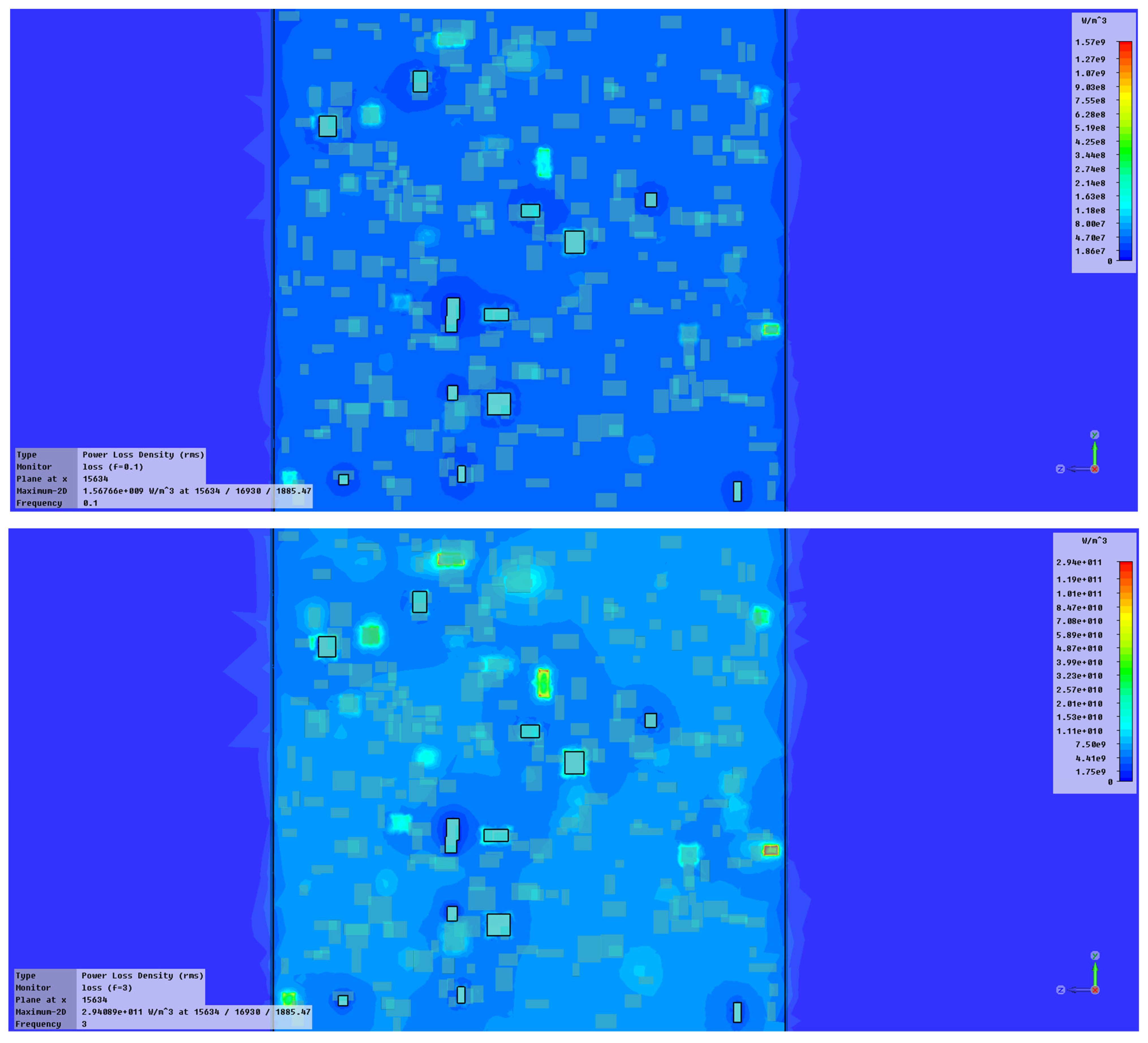
- Ciobanu, R.C.; Damian, R.F.; Schreiner, C.M.; Aradoaei, M.; Sover, A.; Raichur, A.M. Simulation of Dielectric Properties of Nanocomposites with Non-Uniform Filler Distribution. Polymers 2023, 15, 1636. [Google Scholar] [CrossRef] [PubMed]
- Golchinvafa, S.; Masoudpanah, S.M.; Alamolhoda, S. Ultra-broadband FeNi3/NiZnFe2O4/ZnO composite powders for microwave absorption. J. Mater. Res. Technol. 2022, 21, 1737–1748. [Google Scholar] [CrossRef]
- NETZSCH Gerätebau GmbH. Operating Instructions-Simultaneous TG-DTA/DSC Apparatus (STA 449F3) Jupiter; NETZSCH Gerätebau GmbH: Selb, Germany, 2008. [Google Scholar]
- Dong, J.; Wang, C.; Fan, X.; Wei, L.; Shen, G.; Sun, R.; Li, R. Mechanical and dielectric properties of a flexible anisotropic rubber-based composite. Nanomaterials 2022, 12, 2182. [Google Scholar] [CrossRef] [PubMed]
- Durometer Shore Hardness Scale. Available online: https://www.smooth-on.com/page/durometer-shore-hardness-scale/ (accessed on 16 May 2023).


| Property | Value |
|---|---|
| Hardness—Shore A (after 24 h) | 43 ± 3 |
| A/B Mix Ratio (weight parts) | 100/100 |
| Reproduction detail (micron) | 2 |
| Mixing time/minutes, at 23 °C | 2′ |
| Working time/minutes, at 23 °C | 10′–12′ |
| Total demolding time, at 23 °C (hours) | 1–1 h 30′ |
| Dimensional variation (after 24 h) | 0.05% |
| Mixture viscosity—centipoise (cP) | 4000 ± 300 |
| Elongation to break—% | 370 ± 20% |
| Breaking strength (DIE B—N/mm) | 3.5 ± 0.5 |
| Composite Material | Composition (%) HT45/NiFe2O4 |
|---|---|
| S0 | 100/0 |
| S1 | 50/50 |
| S2 | 40/60 |
| S3 | 30/70 |
| S4 | 20/80 |
| Encoding | S0 | S1 | S2 | S3 | S4 |
|---|---|---|---|---|---|
| The density (g/cm3) | 1.004 | 1.642 | 1.924 | 2.150 | 2.594 |
| Frequency (Hz) | S0 | S1 | S2 | S3 | S4 | |
|---|---|---|---|---|---|---|
| Magnetic Permeability (μ) | ||||||
| 0 | 1.99E+04 | 2.24E+04 | 9.83E+03 | 1.58E+04 | 3.71E+04 | |
| 1000 | 1.17E+01 | 7.79E+02 | 8.54E+02 | 1.52E+03 | 3.15E+03 | |
| 5000 | 9.85E−01 | 3.84E+01 | 8.01E+01 | 5.99E+02 | 9.56E+02 | |
| 10,000 | 8.99E−01 | 1.16E+02 | 8.00E+01 | 1.79E+02 | 3.78E+01 | |
| 50,000 | 1.32E+00 | 1.71E+01 | 8.37E+00 | 7.30E+00 | 1.28E+01 | |
| 100,000 | 1.28E+00 | 9.72E+00 | 7.08E+00 | 2.43E+00 | 1.84E+01 | |
| Frequency (Hz) | S0 (dB) | S1 (dB) | S2 (dB) | S3 (dB) | S4 (dB) |
| 10 | 15.82 | 50.01 | 51.86 | 53.21 | 61.30 |
| 1000 | 15.86 | 38.89 | 39.32 | 44.59 | 51.15 |
| 2000 | 15.88 | 30.64 | 37.79 | 42.91 | 46.73 |
| Average up to 2000 Hz | 16 | 40 | 43 | 47 | 53 |
| 2500 | 15.90 | 28.80 | 30.61 | 41.82 | 46.53 |
| 3000 | 15.91 | 27.08 | 32.05 | 41.67 | 41.70 |
| 3500 | 15.92 | 28.42 | 38.01 | 43.35 | 44.86 |
| 4000 | 15.92 | 28.50 | 31.67 | 40.97 | 45.20 |
| 4500 | 15.93 | 26.41 | 34.01 | 39.28 | 42.08 |
| Average up to 4500 Hz | 16 | 32 | 37 | 43 | 47 |
| Composite Material | Frequency Range (Hz) | |||||
|---|---|---|---|---|---|---|
| 102 Hz | 106 Hz | 109 Hz | ||||
| SER | SEA | SER | SEA | SER | SEA | |
| S0 | 8 | 0 | 12 | 6 × 10⁻⁴ | 24.5 | 0.08 |
| S1 | 52 | 0 | 22 | 10−4 | 39 | 0.0035 |
| S2 | 60 | 0 | 30 | 10−4 | 46 | 0.0029 |
| S3 | 41 | 0 | 28.5 | 10−4 | 41 | 0.0035 |
| S4 | 34 | 0 | 32.5 | 3 × 10⁻⁴ | 46 | 0.0044 |
| Sample Code | Hardness Value |
|---|---|
| S1 | 15 |
| S2 | 17 |
| S3 | 20 |
| S4 | 25 |
Disclaimer/Publisher’s Note: The statements, opinions and data contained in all publications are solely those of the individual author(s) and contributor(s) and not of MDPI and/or the editor(s). MDPI and/or the editor(s) disclaim responsibility for any injury to people or property resulting from any ideas, methods, instructions or products referred to in the content. |
© 2023 by the authors. Licensee MDPI, Basel, Switzerland. This article is an open access article distributed under the terms and conditions of the Creative Commons Attribution (CC BY) license (https://creativecommons.org/licenses/by/4.0/).
Share and Cite
Caramitu, A.R.; Ciobanu, R.C.; Ion, I.; Schreiner, C.M.; Aradoaei, M.; Tsakiris, V.; Pintea, J.; Marinescu, V. Flexible Electromagnetic Shielding Nano-Composites Based on Silicon and NiFe2O4 Powders. Polymers 2023, 15, 2447. https://doi.org/10.3390/polym15112447
Caramitu AR, Ciobanu RC, Ion I, Schreiner CM, Aradoaei M, Tsakiris V, Pintea J, Marinescu V. Flexible Electromagnetic Shielding Nano-Composites Based on Silicon and NiFe2O4 Powders. Polymers. 2023; 15(11):2447. https://doi.org/10.3390/polym15112447
Chicago/Turabian StyleCaramitu, Alina R., Romeo C. Ciobanu, Ioana Ion, Cristina M. Schreiner, Mihaela Aradoaei, Violeta Tsakiris, Jana Pintea, and Virgil Marinescu. 2023. "Flexible Electromagnetic Shielding Nano-Composites Based on Silicon and NiFe2O4 Powders" Polymers 15, no. 11: 2447. https://doi.org/10.3390/polym15112447