
Polypropylene-Based Polymer Locking Ligation System Manufacturing by the Ultrasonic Micromolding Process

 , , ,
, , ,  and
and
Abstract
:1. Introduction
2. Materials and Methods
2.1. Materials
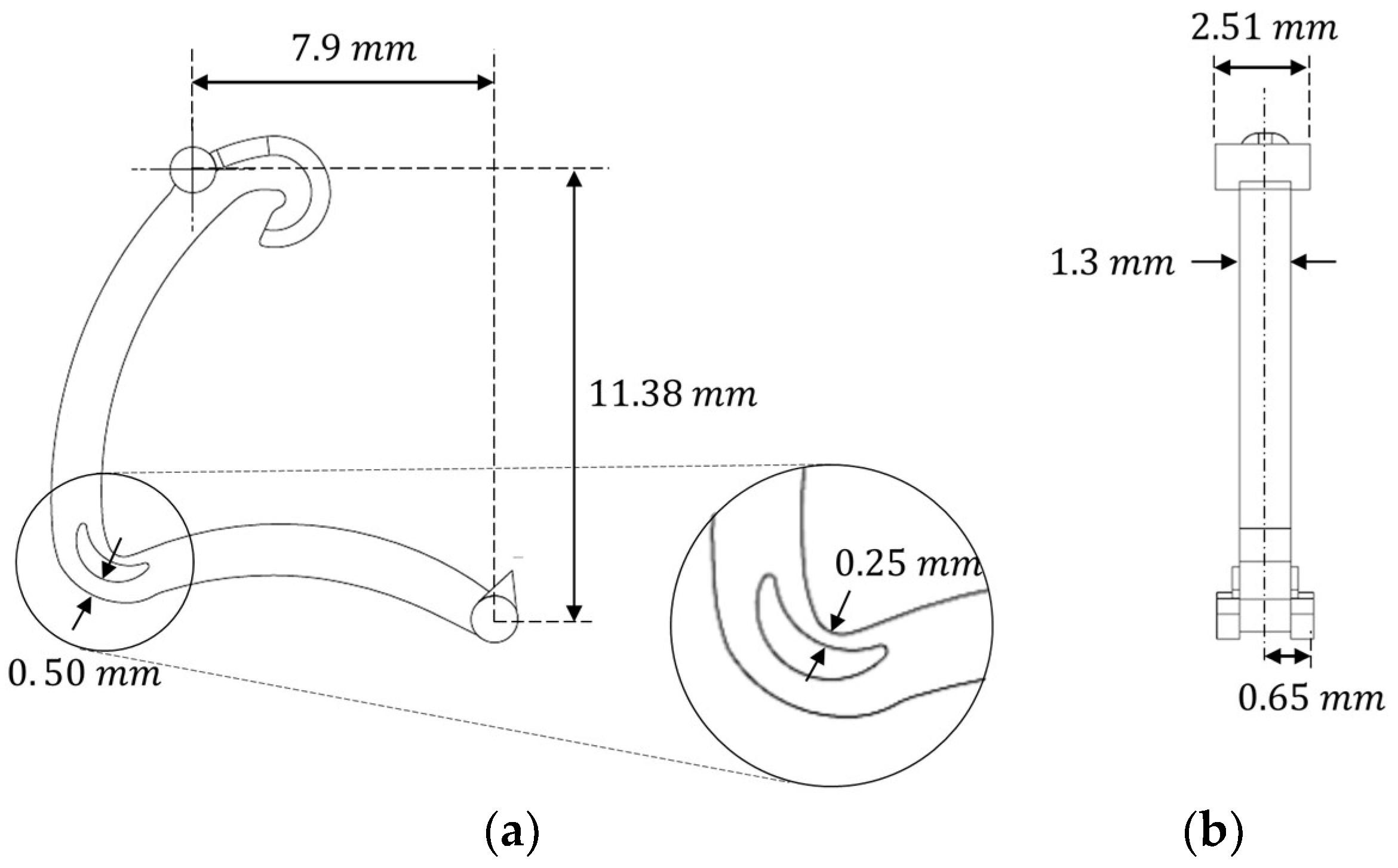
2.2. Component Selection
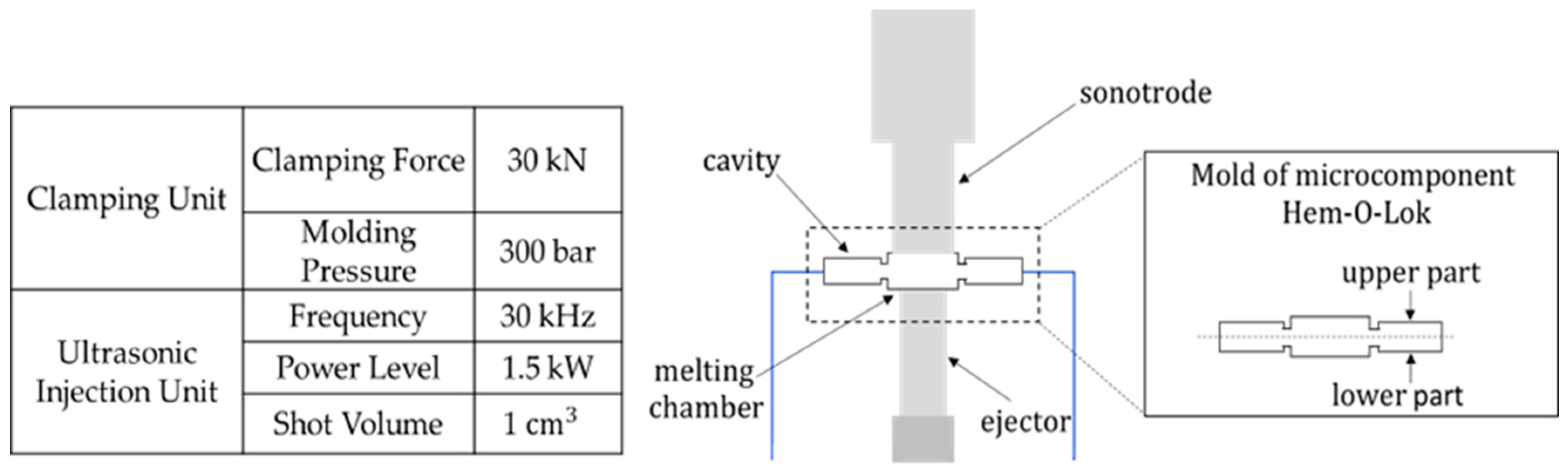
2.3. Operation of Ultrasonic Molding Machine
2.4. Mold Design and Manufacture
2.5. Ultrasonic Molding Machine Setup
2.6. Characterization Methods
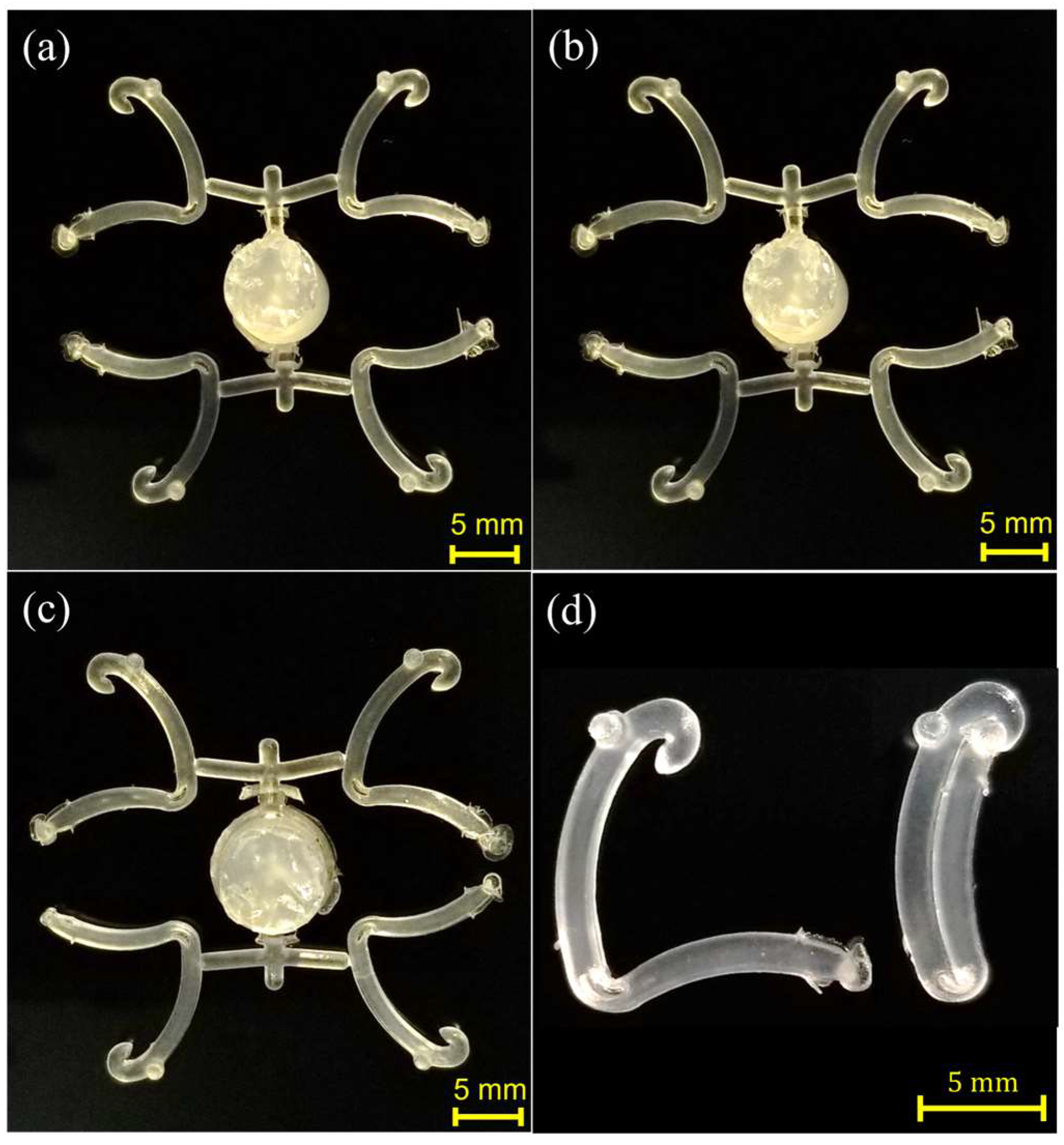
3. Results
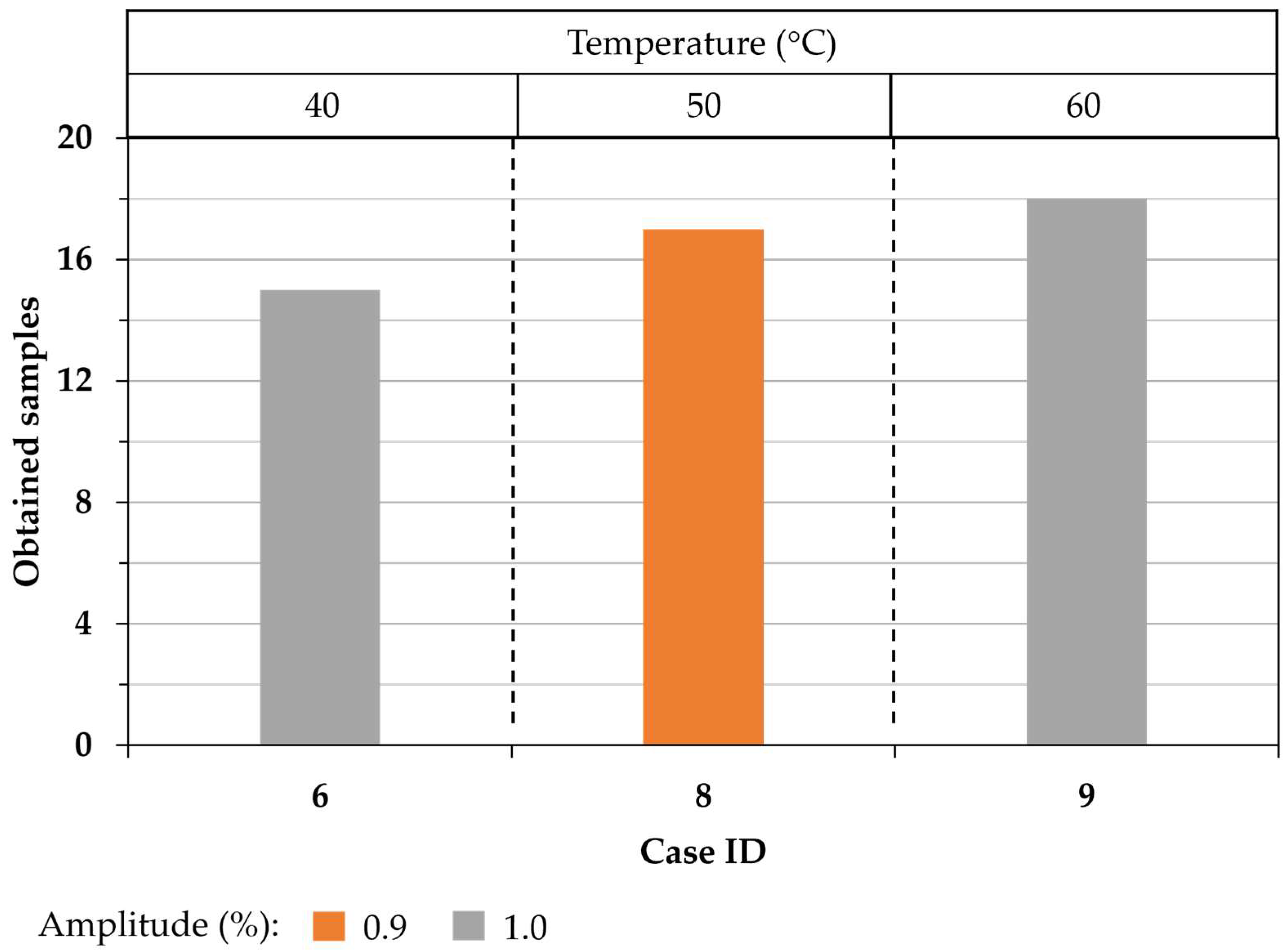
Screening
4. Conclusions
Author Contributions
Funding
Institutional Review Board Statement
Data Availability Statement
Acknowledgments
Conflicts of Interest
References
- Whiteside, B.R.; Martyn, M.T.; Coates, P.D.; Allan, P.S.; Hornsby, P.R.; Greenway, G. Micromoulding: Process characteristics and product properties. Plast. Rubber Compos. 2003, 32, 231–239. [Google Scholar] [CrossRef]
- Sackmann, J.; Burlage, K.; Gerhardy, C.; Memering, B.; Liao, S.; Schomburg, W.K. Review on ultrasonic fabrication of polymer micro devices. Ultrasonics 2015, 56, 189–200. [Google Scholar] [CrossRef] [PubMed]
- Negre, P.; Grabalosa, J.; Ferrer, I.; Ciurana, J.; Elías-Zúñiga, A.; Rivillas, F. Study of the Ultrasonic Molding Process Parameters for Manufacturing Polypropylene Parts. Procedia Eng. 2015, 132, 7–14. [Google Scholar] [CrossRef]
- Michaeli, W.; Starke, C. Ultrasonic investigations of the thermoplastics injection moulding process. Polym. Test. 2005, 24, 205–209. [Google Scholar] [CrossRef]
- Planellas, M.; Sacristán, M.; Rey, L.; Olmo, C.; Aymamí, J.; Casas, M.T.; Del Valle, L.J.; Franco, L.; Puiggalí, J. Micro-molding with ultrasonic vibration energy: New method to disperse nanoclays in polymer matrices. Ultrason. Sonochem. 2014, 21, 1557–1569. [Google Scholar] [CrossRef] [PubMed]
- Grabalosa, J.; Ferrer, I.; Martínez-Romero, O.; Elías-Zúñiga, A.; Plantá, X.; Rivillas, F. Assessing a stepped sonotrode in ultrasonic molding technology. J. Mater. Process. Technol. 2016, 229, 687–696. [Google Scholar] [CrossRef]
- Michaeli, W.; Opfermann, D. Ultrasonic Plasticising for Micro Injection Moulding; Woodhead Publishing Limited: Sawston, UK, 2006. [Google Scholar]
- Folgueral, M. New Process and Machinery for Microparts Moulding Based on Ultrasound Excitation. Final Rep. Sonoplast 2011, 1–9. [Google Scholar]
- Vázquez, E.; Amaro, A.; Ciurana, J.; Rodríguez, C.A. Process planning considerations for micromilling of mould cavities used in ultrasonic moulding technology. Precis. Eng. 2015, 39, 252–260. [Google Scholar] [CrossRef]
- Seo, Y.S.; Park, K. Direct patterning of micro-features on a polymer substrate using ultrasonic vibration. Microsyst. Technol. 2012, 18, 2053–2061. [Google Scholar] [CrossRef]
- Sato, A.; Ito, H.; Koyama, K. Study of application of ultrasonic wave to injection molding. Polym. Eng. Sci. 2009, 49, 768–773. [Google Scholar] [CrossRef]
- Wang, D.A.; Nguyen, H.D. A planar Bézier profiled horn for reducing penetration force in ultrasonic cutting. Ultrasonics 2014, 54, 375–384. [Google Scholar] [CrossRef] [PubMed]
- Zhao, P.; Wang, S.; Ying, J.; Fu, J. Non-destructive measurement of cavity pressure during injection molding process based on ultrasonic technology and Gaussian process. Polym. Test. 2013, 32, 1436–1444. [Google Scholar] [CrossRef]
- Wu, S.Y.; Wu, X.Y.; Xu, B.; Cheng, R.; Luo, F.; Ruan, S.C. A micro-ultrasonic powder moulding method to fabricate Sn-Bi alloy micro parts. J. Mater. Process. Technol. 2014, 214, 2668–2675. [Google Scholar] [CrossRef]
- Luo, W.Y.; Wu, X.Y.; Wu, S.Y.; Xu, B.; Cheng, R.; Ruan, S.C. Micro-ultrasonic powder moulding of Sn-Bi/Cu composite micro parts in semisolid form. J. Mater. Process. Technol. 2015, 223, 313–318. [Google Scholar] [CrossRef]
- Liang, X.; Liu, Y.; Liu, Z.; Ma, J.; Zhang, Z.; Ruan, W.; Ren, S.; Peng, T.; Wu, X.; Shi, H. Materials & Design Ultrasonic injection molding of glass fiber reinforced polypropylene parts using tungsten carbide-cobalt mold core. Mater. Des. 2021, 205, 109771. [Google Scholar] [CrossRef]
- Gaxiola-Cockburn, R.; Martínez-Romero, O.; Elías-Zúñiga, A.; Olvera-Trejo, D.; Reséndiz-Hernández, J.E.; Soria-Hernández, C.G. Investigation of the mechanical properties of parts fabricated with ultrasonic micro injection moldingprocess using polypropylene recycled material. Polymers 2020, 12, 2033. [Google Scholar] [CrossRef]
- Liang, X.; Liu, Y.; Ma, J.; Gong, F.; Lou, Y.; Fu, L.; Xu, B. Fabrication of micro ultrasonic powder molding polypropylene part with hydrophobic patterned surface. Materials 2020, 13, 3247. [Google Scholar] [CrossRef]
- Heredia-Rivera, U.; Ferrer, I.; Vázquez, E. Ultrasonic molding technology: Recent advances and potential applications in the medical industry. Polymers 2019, 11, 667. [Google Scholar] [CrossRef]
- Grabalosa, J.; Ferrer, I.; Elías-Zúñiga, A.; Ciurana, J. Influence of processing conditions on manufacturing polyamide parts by ultrasonic molding. Mater. Des. 2016, 98, 20–30. [Google Scholar] [CrossRef]
- Estrada, P.; Siller, H.R.; Vázquez, E.; Rodríguez, C.A.; Martínez-Romero, O.; Corona, R. Micro-injection Moulding of Polymer Locking Ligation Systems. Procedia CIRP 2016, 49, 1–7. [Google Scholar] [CrossRef]
- Rännar, L.-E. On Optimization of Injection Molding Cooling. Ph.D. Thesis, Norwegian University of Science and Technology, Trondheim, The Netherlands, 2008. [Google Scholar]
- Ko´sciuszko, A.K.; Marciniak, D.; Sykutera, D. Post-Processing Time Dependence of Shrinkage and Mechanical Properties of Injection-Molded Polypropylene. Materials 2021, 14, 22. [Google Scholar] [CrossRef]
- Gopanna, A.; Mandapati, R.N.; Thomas, S.P.; Rajan, K.; Chavali, M. Fourier transform infrared spectroscopy (FTIR), Raman spectroscopy and wide-angle X-ray scattering (WAXS) of polypropylene (PP)/cyclic olefin copolymer (COC) blends for qualitative and quantitative analysis. Polym. Bull. 2019, 76, 4259–4274. [Google Scholar] [CrossRef]
- Fang, J.; Zhang, L.; Sutton, D.; Wang, X.; Lin, T. Needleless melt-electrospinning of polypropylene nanofibres. J. Nanomater. 2012, 2012, 382639. [Google Scholar] [CrossRef]
- Sánchez-Sánchez, X.; Hernández-Avila, M.; Elizalde, L.E.; Martínez, O.; Ferrer, I.; Elías-Zuñiga, A. Micro injection molding processing of UHMWPE using ultrasonic vibration energy. Mater. Des. 2017, 132, 1–12. [Google Scholar] [CrossRef]


| Pellets per Shot | Plunger Force (N) | Work Pressure (bar) | Plunger Feeding Position (mm) | US Time (s) |
|---|---|---|---|---|
| 19 | 6500 | 3 | −15, −11, −8, −6, −3 | 4 |
| Vibration Amplitude (%) | Mold Temperature (°C) | Plunger Velocity Profile (mm/s) | ||
| 0.8, 0.9, 1.0 | 40, 50, 60 | I: 3, 3, 3, 3, 3 | ||
| 0.8, 0.9, 1.0 | 40, 50, 60 | II: 2, 2, 4, 4, 6 | ||
| 0.8, 0.9, 1.0 | 40, 50, 60 | III: 2, 2, 7, 7, 10 | ||
| Case ID | 1 | 2 | 3 | 4 | 5 | 6 | 7 | 8 | 9 | 10 | 11 | 12 | 13 | 14 | 15 | 16 | 17 | 18 | 19 | 20 | 21 | 22 | 23 | 24 | 25 | 26 | 27 |
| Vibration Amplitude | 0.8 | 0.9 | 1.0 | 0.8 | 0.9 | 1.0 | 0.8 | 0.9 | 1.0 | 0.8 | 0.9 | 1.0 | 0.8 | 0.9 | 1.0 | 0.8 | 0.9 | 1.0 | 0.8 | 0.9 | 1.0 | 0.8 | 0.9 | 1.0 | 0.8 | 0.9 | 1.0 |
| Mold Temperature (°C) | 40 | 50 | 60 | 40 | 50 | 60 | 40 | 50 | 60 | ||||||||||||||||||
| Plunger Velocity Profile (mm/s) | I | II | III | ||||||||||||||||||||||||
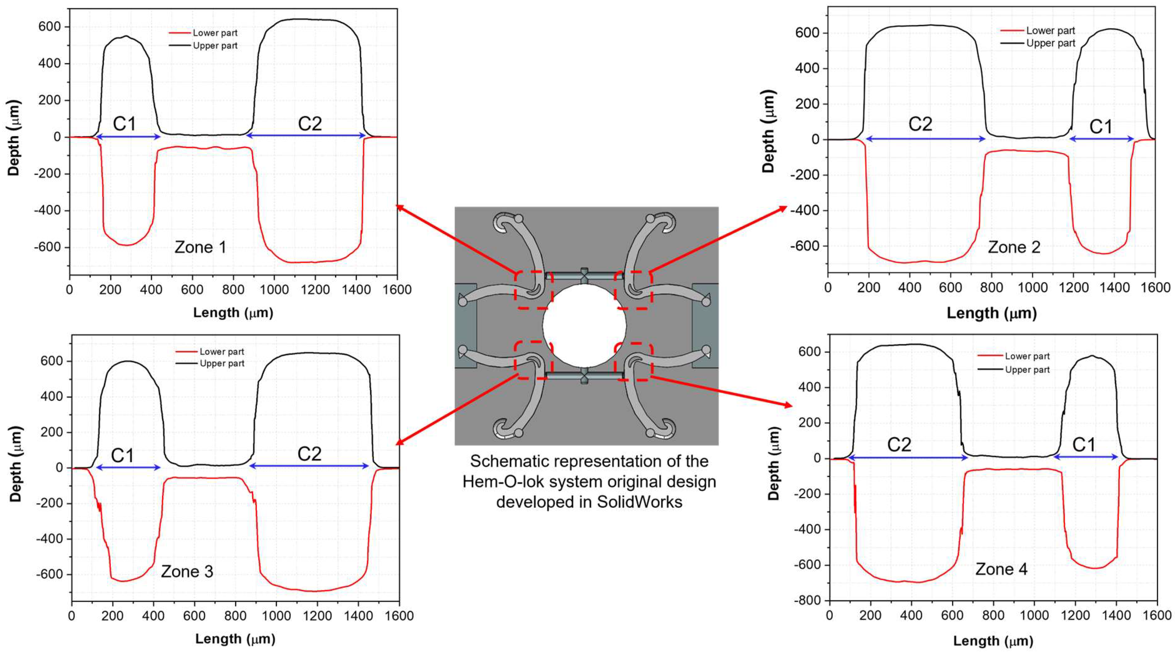
| Zone | Average | Standard Deviation | |||||
| 1 | 2 | 3 | 4 | ||||
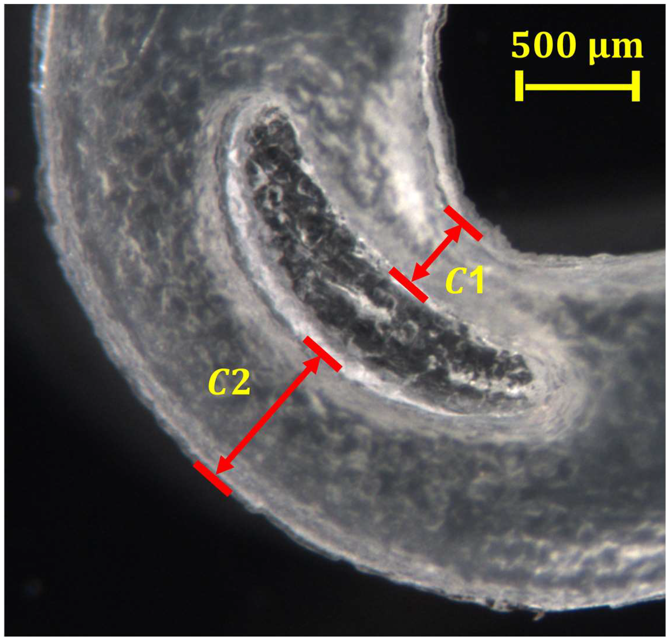
| Critical microfeature 1 | |||||||
| Microdevice samples | Lower part | 268.07 | 268.62 | 268.29 | 269.36 | 268.58 | 0.49 |
| Upper part | 260.00 | 260.02 | 313.85 | 260.20 | 273.52 | 23.28 | |
| Mold cavity | Lower part | 283.93 | 286.22 | 282.71 | 282.55 | 283.85 | 1.47 |
| Upper part | 237.59 | 343.36 | 313.21 | 269.93 | 291.02 | 40.41 | |
| Critical microfeature 2 | |||||||
| Microdevice samples | Lower part | 524.36 | 573.56 | 540.09 | 515.55 | 538.38 | 19.79 |
| Upper part | 544.88 | 544.98 | 585.49 | 542.59 | 554.49 | 20.26 | |
| Mold cavity | Lower part | 581.10 | 557.54 | 556.87 | 558.93 | 563.61 | 10.13 |
| Upper part | 509.73 | 579.07 | 577.64 | 517.00 | 545.86 | 32.60 | |
Disclaimer/Publisher’s Note: The statements, opinions and data contained in all publications are solely those of the individual author(s) and contributor(s) and not of MDPI and/or the editor(s). MDPI and/or the editor(s) disclaim responsibility for any injury to people or property resulting from any ideas, methods, instructions or products referred to in the content. |
© 2023 by the authors. Licensee MDPI, Basel, Switzerland. This article is an open access article distributed under the terms and conditions of the Creative Commons Attribution (CC BY) license (https://creativecommons.org/licenses/by/4.0/).
Share and Cite
Elías-Grajeda, A.; Vázquez-Lepe, E.; Siller, H.R.; Perales-Martínez, I.A.; Reséndiz-Hernández, E.; Ramírez-Herrera, C.A.; Olvera-Trejo, D.; Martínez-Romero, O. Polypropylene-Based Polymer Locking Ligation System Manufacturing by the Ultrasonic Micromolding Process. Polymers 2023, 15, 3049. https://doi.org/10.3390/polym15143049
Elías-Grajeda A, Vázquez-Lepe E, Siller HR, Perales-Martínez IA, Reséndiz-Hernández E, Ramírez-Herrera CA, Olvera-Trejo D, Martínez-Romero O. Polypropylene-Based Polymer Locking Ligation System Manufacturing by the Ultrasonic Micromolding Process. Polymers. 2023; 15(14):3049. https://doi.org/10.3390/polym15143049
Chicago/Turabian StyleElías-Grajeda, Alex, Elisa Vázquez-Lepe, Héctor R. Siller, Imperio Anel Perales-Martínez, Emiliano Reséndiz-Hernández, Claudia Angélica Ramírez-Herrera, Daniel Olvera-Trejo, and Oscar Martínez-Romero. 2023. "Polypropylene-Based Polymer Locking Ligation System Manufacturing by the Ultrasonic Micromolding Process" Polymers 15, no. 14: 3049. https://doi.org/10.3390/polym15143049