
Effects of Electron Irradiation and Temperature on Mechanical Properties of Polyimide Film

 and
and
Abstract
:1. Introduction
2. Materials and Methods
3. Results
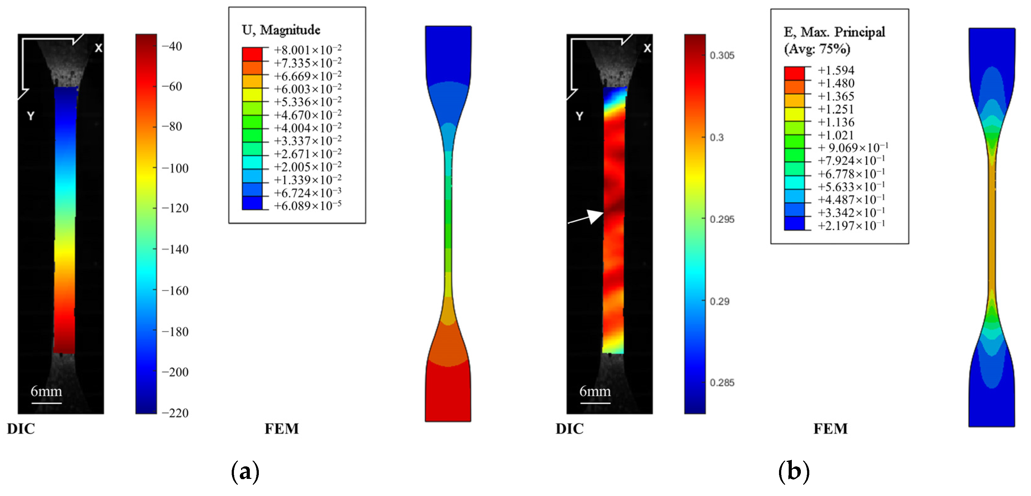
3.1. Uniaxial Tensile Test
3.1.1. Effect of Electron Irradiation
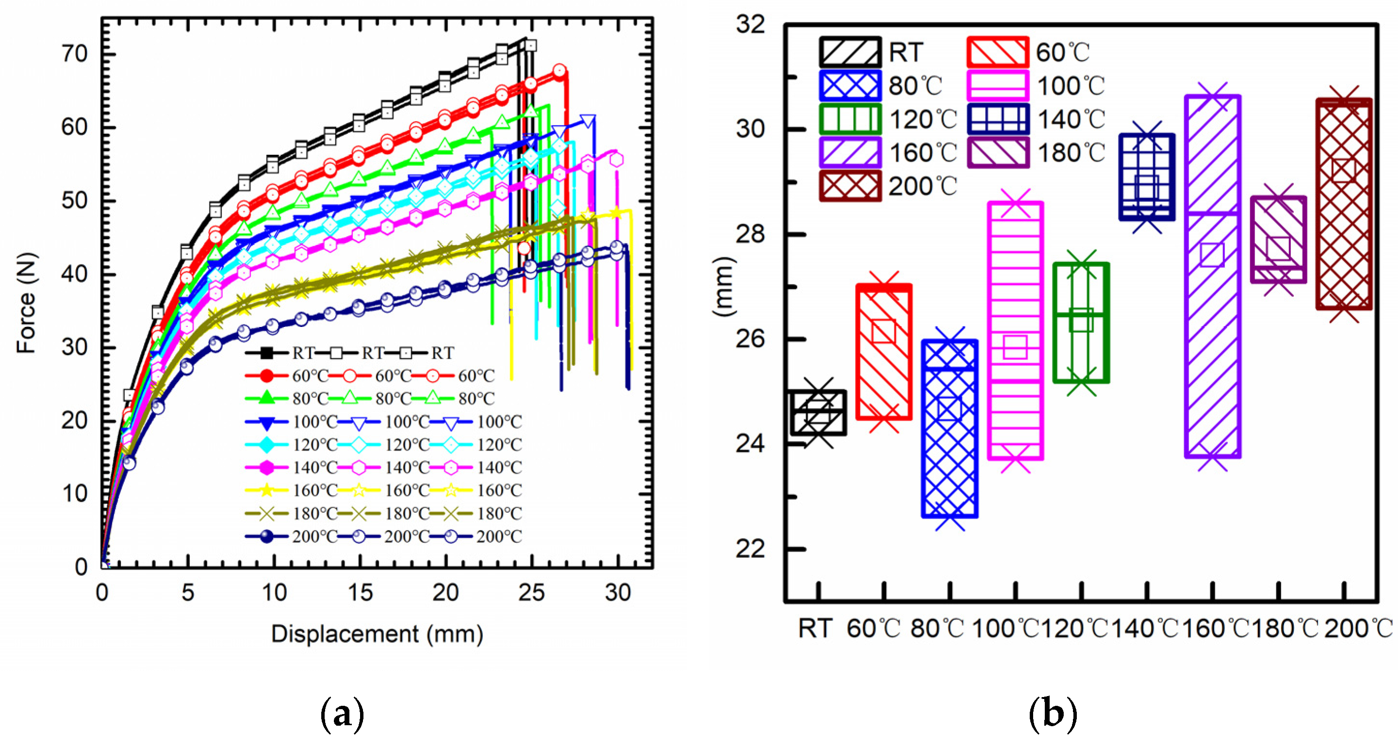
3.1.2. Effect of High Temperature
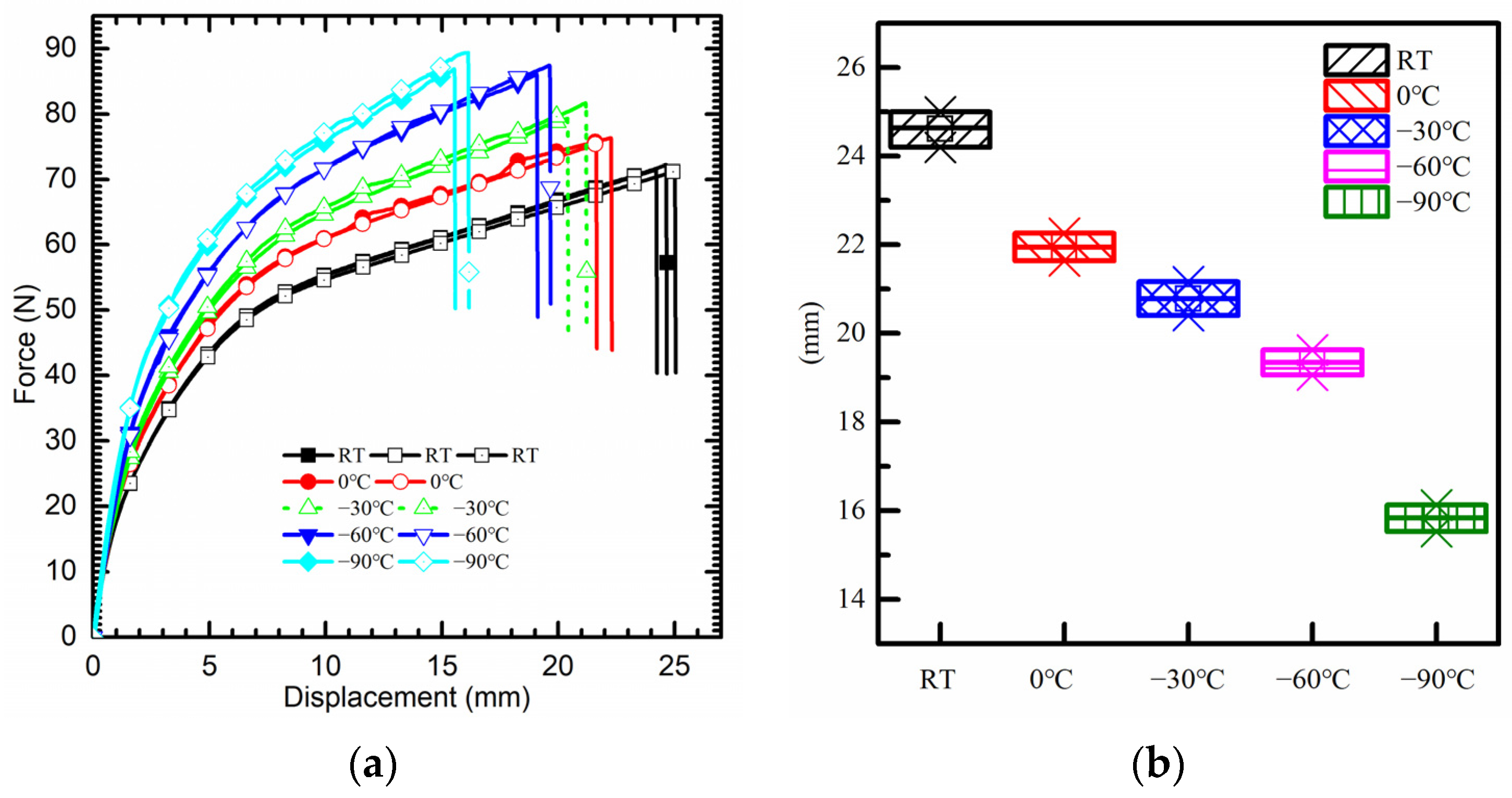
3.1.3. Effect of Low Temperature
3.2. DMA Test
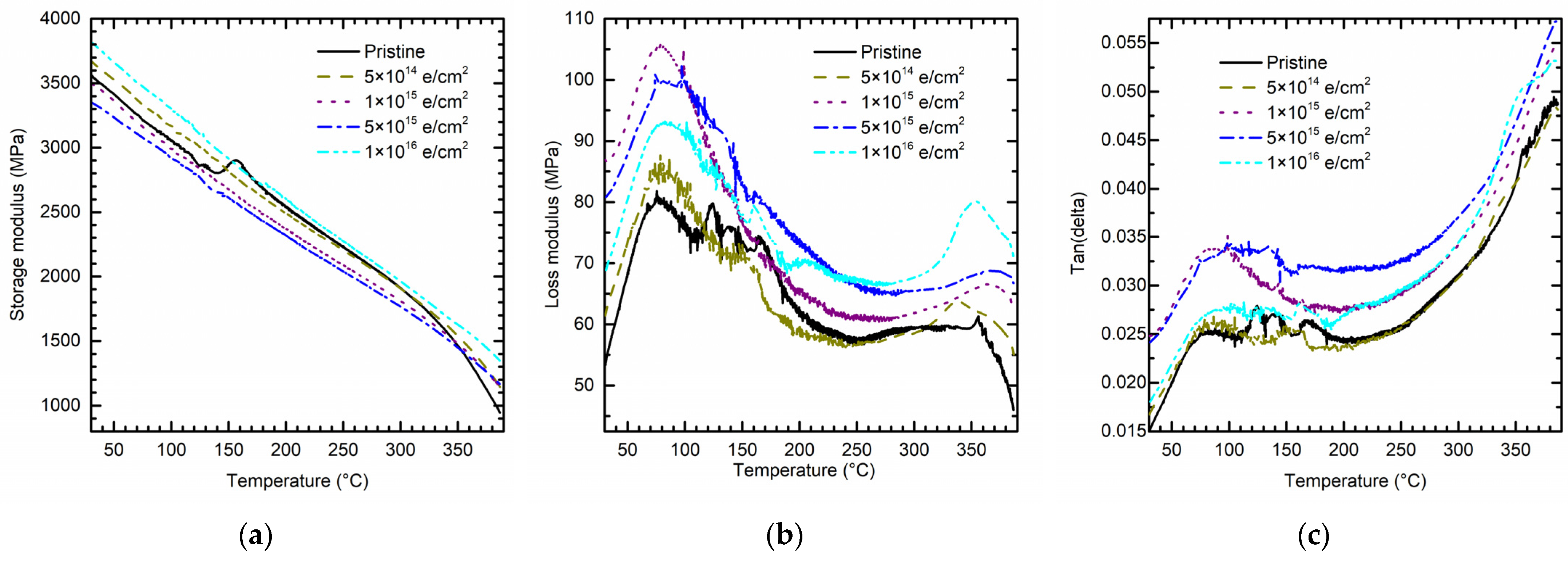
3.2.1. Effect of Electron Irradiation and High Temperature
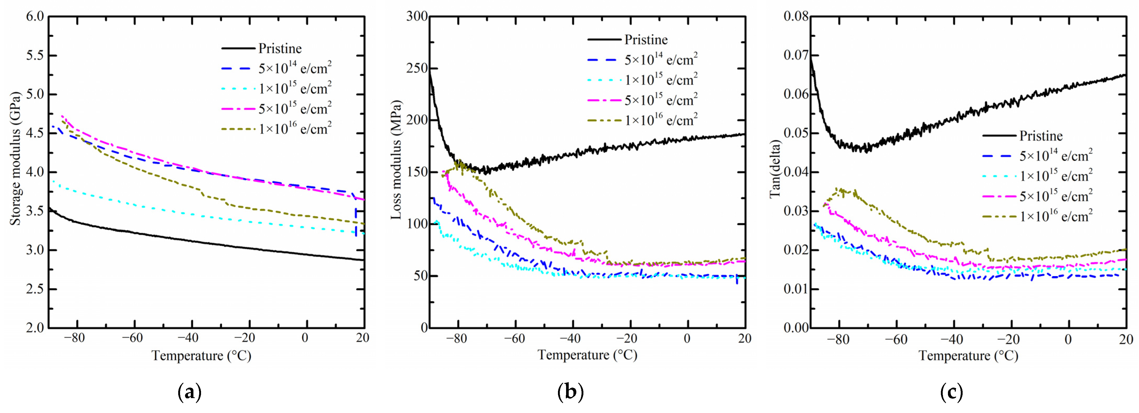
3.2.2. Effect of Electron Irradiation and Low Temperature
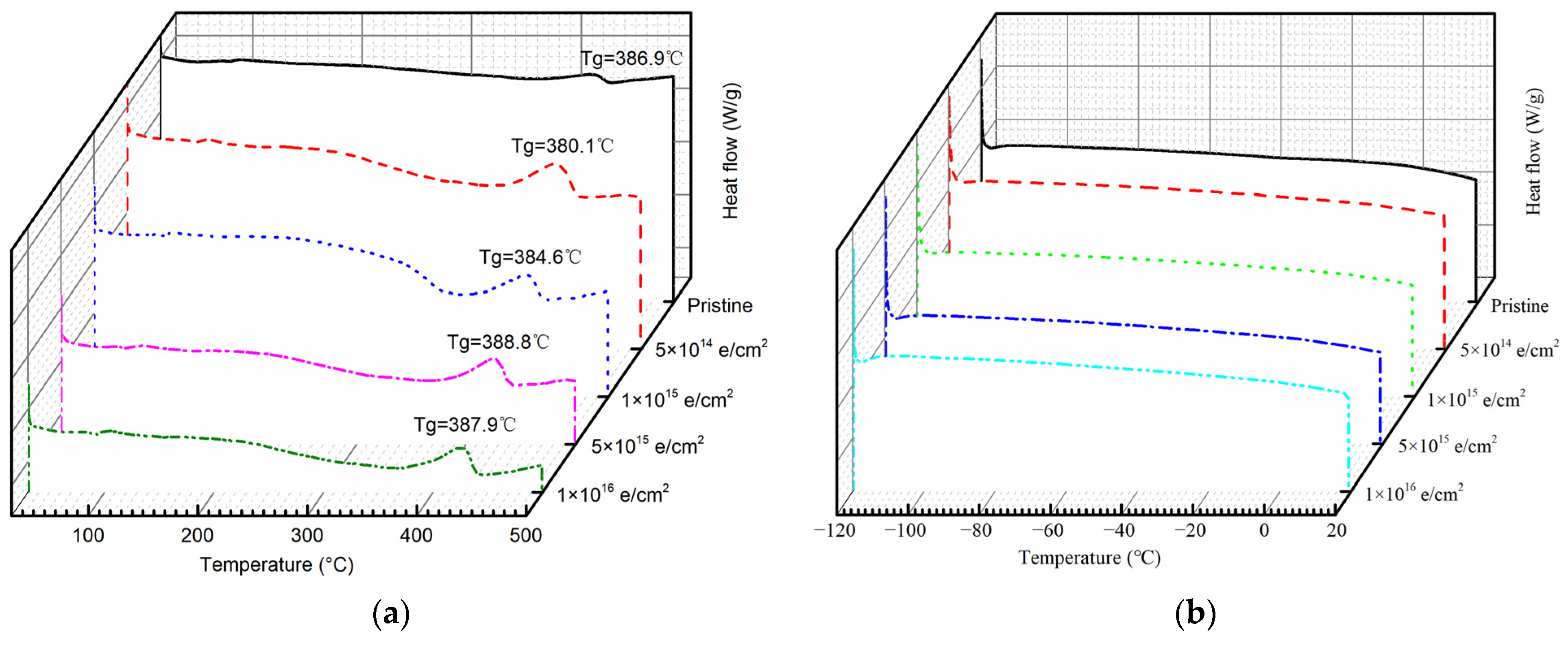
3.3. Changes in Thermal Properties
3.4. Changes in Morphology
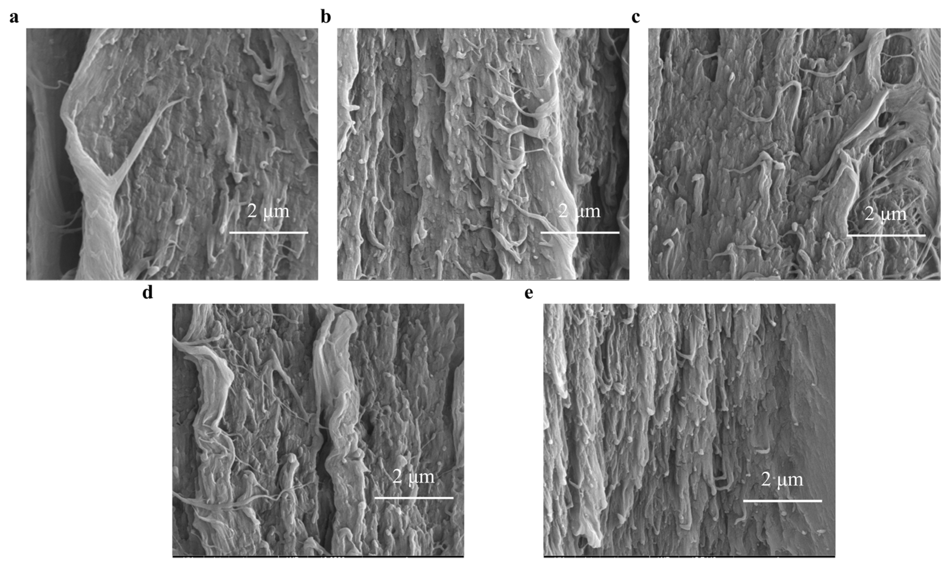
3.4.1. Morphology Changes on Fracture Surface
3.4.2. Morphology Changes on the Surface
4. Discussion and Conclusions
Author Contributions
Funding
Institutional Review Board Statement
Data Availability Statement
Acknowledgments
Conflicts of Interest
Appendix A

| Pristine | 5 × 10¹⁴ e/cm2 | 1 × 10¹⁵ e/cm2 | 5 × 10¹⁵ e/cm2 | 1 × 10¹⁶ e/cm2 | |
|---|---|---|---|---|---|
| Area 1 | 2.606 nm | 2.375 nm | 2.758 nm | 2.14 nm | 3.05 nm |
| Area 2 | 2.646 nm | 2.132 nm | 2.931 nm | 1.88 nm | 2.559 nm |
| Area 3 | 2.556 nm | 2.447 nm | 2.521 nm | 2.334 nm | 2.538 nm |
| Mean Ra | 2.603 nm | 2.318 nm | 2.737 nm | 2.118 nm | 2.716 nm |
| 0.045094346 | 0.165054536 | 0.205831242 | 0.227798156 | 0.289731773 |
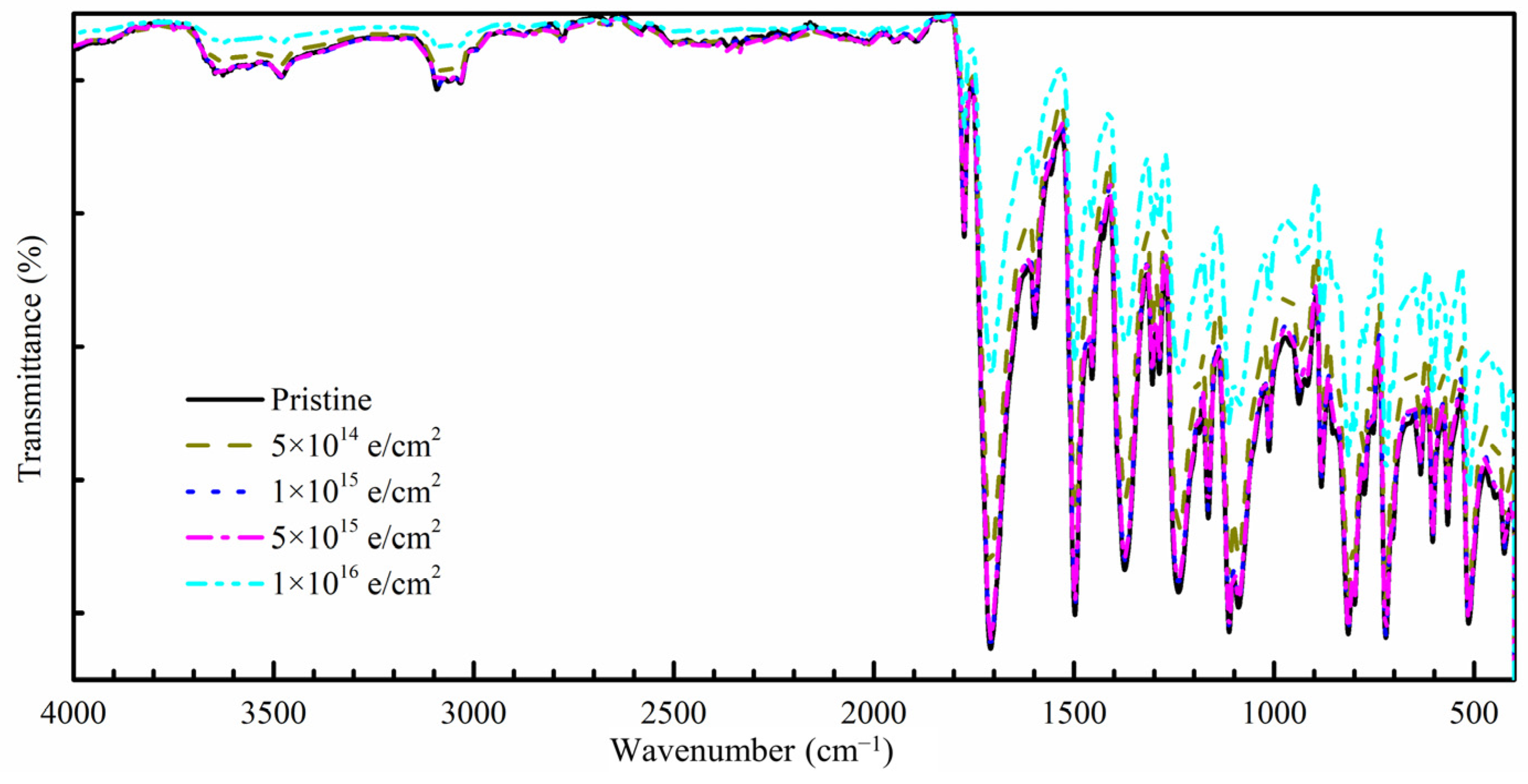
| Wavenumbers | Pristine | 5 × 10¹⁴ e/cm2 | 1 × 10¹⁵ e/cm2 | 5 × 10¹⁵ e/cm2 | 1 × 10¹⁶ e/cm2 |
|---|---|---|---|---|---|
| 2932 cm−1 | 97.2 | 97.3 | 97.4 | 97.2 | 98.3 |
| 1775 cm−1 | 67.5 | 73.3 | 68.4 | 68.4 | 83.3 |
| 1718 cm−1 | 15.0 | 26.5 | 15.7 | 16.6 | 52.0 |
| 1500 cm−1 | 11.8 | 23.6 | 13.2 | 14.0 | 49.5 |
| 1375 cm−1 | 16.7 | 27.5 | 18.1 | 18.7 | 50.9 |
| 1242 cm−1 | 13.5 | 23.3 | 14.9 | 15.5 | 46.8 |

References
- Wang, K.; Wang, X.; Qian, B.; Ma, J.; Lu, J. Recent Development OnSpace Application for High-Efficiency Solar Cells and Array Technology. Kuei Suan Jen Hsueh Pao/J. Chin. Ceram. Soc. 2022, 50, 1436–1446. [Google Scholar]
- Zhang, F.; Han, W.; Chen, H.; He, H.; Wang, X. The Design of Flexible Printed Circuit in Solar Cell Array and Experimental Study of Its Thermal Adaptability. Spacecr. Environ. Eng. 2021, 38, 670–676. [Google Scholar] [CrossRef]
- Yin, M.S.; Yang, G.; Wang, X.C.; Fan, B.; Jiang, D.P.; Yang, H.D. Strain-Testing Research of Space Solar Cell Array. Wuli Xuebao/Acta Phys. Sin. 2021, 70, 198801. [Google Scholar] [CrossRef]
- Miller, S.K.R.; Dever, J.A. Space Environment Exposure Results from the MISSE 5 Polymer Film Thermal Control Experiment on the International Space Station. In Proceedings of the 11th International Symposium on Materials in the Space Environment, Aix-en-Provence, France, 15–18 September 2009; p. 7. [Google Scholar]
- Miller, S.K.R.; Dever, J.A.; Banks, B.A.; Kline, S. MISSE 6 Polymer Film Tensile Experiment. In Proceedings of the 2010 National Space and Missile Materials Symposium (NSMMS), Scottsdale, AZ, USA, 28 June–1 July 2010; p. 13. [Google Scholar]
- Miller, S.K.R.; Banks, B.A.; Sechkar, E. An Investigation of Stress Dependent Atomic Oxygen Erosion of Black Kapton Observed on MISSE 6. In Proceedings of the 2010 National Space and Missile Materials Symposium (NSMMS), Scottsdale, AZ, USA, 28 June–1 July 2010; p. 8. [Google Scholar]
- Miller, S.K.R.; Sechkar, E.A. An Examination of Radiation Induced Tensile Failure of Stressed and Unstressed Polymer Films Flown on MISSE 6. 2013. Available online: https://ntrs.nasa.gov/api/citations/20130001603/downloads/20130001603.pdf (accessed on 8 September 2023).
- Shimamura, H.; Nakamura, T. Investigation of Degradation Mechanisms in Mechanical Properties of Polyimide Films Exposed to a Low Earth Orbit Environment. Polym. Degrad. Stab. 2010, 95, 21–33. [Google Scholar] [CrossRef]
- Shimamura, H.; Yamagata, I. Degradation of Mechanical Properties of Polyimide Film Exposed to Space Environment. J. Spacecr. Rocket. 2012, 46, 15–21. [Google Scholar] [CrossRef]
- Shen, Z.; Liang, G.; Ziliang, M.; Yu, B.; Yigang, D.; Yenan, L.; Zhihao, W. Mechanical Property Degradation of Polyimide Film under Gamma Ray Radiation. Spacecr. Environ. Eng. 2016, 33, 100–104. [Google Scholar]
- Dong, S.S.; Shao, W.Z.; Yang, L.; Ye, H.J.; Zhen, L. Surface Characterization and Degradation Behavior of Polyimide Films Induced by Coupling Irradiation Treatment. RSC Adv. 2018, 8, 28152–28160. [Google Scholar] [CrossRef]
- Dong, S.S.; Shao, W.Z.; Yang, L.; Ye, H.J.; Zhen, L. Microstructure Evolution of Polyimide Films Induced by Electron Beam Irradiation-Load Coupling Treatment. Polym. Degrad. Stab. 2018, 155, 230–237. [Google Scholar] [CrossRef]
- Manas, D.; Mizera, A.; Manas, M.; Ovsik, M.; Hylova, L.; Sehnalek, S.; Stoklasek, P. Mechanical Properties Changes of Irradiated Thermoplastic Elastomer. Polymers 2018, 10, 87. [Google Scholar] [CrossRef]
- Manas, D.; Ovsik, M.; Mizera, A.; Manas, M.; Hylova, L.; Bednarik, M.; Stanek, M. The Effect of Irradiation on Mechanical and Thermal Properties of Selected Types of Polymers. Polymers 2018, 10, 158. [Google Scholar] [CrossRef]
- Stelescu, M.D.; Airinei, A.; Manaila, E.; Craciun, G.; Fifere, N.; Varganici, C.; Pamfil, D.; Doroftei, F. Effects of Electron Beam Irradiation on the Mechanical, Thermal, and Surface Properties of Some EPDM/Butyl Rubber Composites. Polymers 2018, 10, 1206. [Google Scholar] [CrossRef]
- Qiu, J.; Heini, M.; Ma, J.; Han, W.; Wang, X.; Yin, J.; Shi, Y.; Gao, C. Mechanical Properties of Multi-Scale Germanium Specimens from Space Solar Cells under Electron Irradiation. Chin. J. Aeronaut. 2023; in press. [Google Scholar] [CrossRef]
- Plis, E.A.; Engelhart, D.P.; Cooper, R.; Johnston, W.R.; Ferguson, D.; Hoffmann, R. Review of Radiation-Induced Effects in Polyimide. Appl. Sci. 2019, 9, 1999. [Google Scholar] [CrossRef]
- Zhang, H.; Liu, H.W.; Hu, Z.Y.; Zhang, W. On-Orbit Load Analysis of Solar Wing with Flexible Characteristics. Yuhang Xuebao/J. Astronaut. 2019, 40, 139–147. [Google Scholar] [CrossRef]
- Sibin, K.P.; Mary Esther, A.C.; Shashikala, H.D.; Dey, A.; Sridhara, N.; Sharma, A.K.; Barshilia, H.C. Environmental Stability of Transparent and Conducting ITO Thin Films Coated on Flexible FEP and Kapton® Substrates for Spacecraft Applications. Sol. Energy Mater. Sol. Cells 2018, 176, 134–141. [Google Scholar] [CrossRef]
- Cherkashina, N.I.; Pavlenko, V.I.; Noskov, A.V. Synthesis and Property Evaluations of Highly Filled Polyimide Composites under Thermal Cycling Conditions from −190 °C to +200 °C. Cryogenics 2019, 104, 102995. [Google Scholar] [CrossRef]
- Kang, P.H.; Jeon, Y.K.; Jeun, J.P.; Shin, J.W.; Nho, Y.C. Effect of Electron Beam Irradiation on Polyimide Film. J. Ind. Eng. Chem. 2008, 14, 672–675. [Google Scholar] [CrossRef]
- Mishra, R.; Tripathy, S.P.; Dwivedi, K.K.; Khathing, D.T.; Ghosh, S.; Müller, M.; Fink, D. Spectroscopic and Thermal Studies of Electron Irradiated Polyimide. Radiat. Meas. 2003, 36, 621–624. [Google Scholar] [CrossRef]
- Sasuga, T. Electron Irradiation Effects on Dynamic Viscoelastic Properties and Crystallization Behaviour of Aromatic Polyimides. Polymer 1991, 32, 1539–1544. [Google Scholar] [CrossRef]
- Hirade, T.; Hama, Y.; Sasuga, T.; Seguchi, T. Radiation Effect of Aromatic Thermoplastic Polyimide (New-TPI). Polymer 1991, 32, 2499–2504. [Google Scholar] [CrossRef]
- Kupchishin, A.I.; Muradov, A.D.; Omarbekova, Z.A.; Taipova, B.G. Mechanooptical Investigations of Polyimide Films Exposed to Electrons, Mechanical Loads, and Temperatures. Russ. Phys. J. 2007, 50, 153–160. [Google Scholar] [CrossRef]
- Space Systems—Space Solar Cells—Electron and Proton Irradiation Test Methods. 2018, Volume 9. Available online: https://www.iso.org/standard/69495.html (accessed on 8 September 2023).
- China, S.A. of Test Method of Electron Irradiation Aerospace Solar Cells. 2019. Available online: http://c.gb688.cn/bzgk/gb/showGb?type=online&hcno=B3F21AA1A502A459C4E7208AD380B3B8 (accessed on 8 September 2023).
- China, S.A. of Plastics—Determination of Tensile Properties—Part 3: Test Conditions for Films and Sheets. 2006. Available online: https://openstd.samr.gov.cn/bzgk/gb/newGbInfo?hcno=39C9E88D2852DFAF876475C8AB7A97E2 (accessed on 8 September 2023).
- Rahnamoun, A.; Engelhart, D.P.; Humagain, S.; Koerner, H.; Plis, E.; Kennedy, W.J.; Cooper, R.; Greenbaum, S.G.; Hoffmann, R.; van Duin, A.C.T. Chemical Dynamics Characteristics of Kapton Polyimide Damaged by Electron Beam Irradiation. Polymer 2019, 176, 135–145. [Google Scholar] [CrossRef]
- Ennis, C.P.; Kaiser, R.I. Mechanistical Studies on the Electron-Induced Degradation of Polymethylmethacrylate and Kapton. Phys. Chem. Chem. Phys. 2010, 12, 14902–14915. [Google Scholar] [CrossRef] [PubMed]
- Zhao, F.; Zhang, H.; Zhang, D.; Wang, X.; Wang, D.; Zhang, J.; Cheng, J.; Gao, F. Molecular Insights into the ‘Defects’ Network in the Thermosets and the Influence on the Mechanical Performance. RSC Adv. 2022, 12, 22342–22350. [Google Scholar] [CrossRef] [PubMed]
- Plis, E.A.; Bengtson, M.T.; Engelhart, D.P.; Badura, G.P.; Cowardin, H.M.; Reyes, J.A.; Hoffmann, R.C.; Sokolovskiy, A.; Ferguson, D.C.; Shah, J.R.; et al. Characterization of Novel Spacecraft Materials under High Energy Electron and Atomic Oxygen Exposure. In Proceedings of the AIAA Science and Technology Forum and Exposition, AIAA SciTech Forum 2022, Virtual, 3–7 January 2022; AIAA: San Diego, CA, USA, 2022; pp. 1–12. [Google Scholar]
- Cherkashina, N.I.; Pavlenko, V.I.; Noskov, A.V.; Romanyuk, D.S.; Sidelnikov, R.V.; Kashibadze, N.V. Effect of Electron Irradiation on Polyimide Composites Based on Track Membranes for Space Systems. Adv. Sp. Res. 2022, 70, 3249–3256. [Google Scholar] [CrossRef]
- Blaber, J.; Adair, B.; Antoniou, A. Ncorr: Open-Source 2D Digital Image Correlation Matlab Software. Exp. Mech. 2015, 55, 1105–1122. [Google Scholar] [CrossRef]
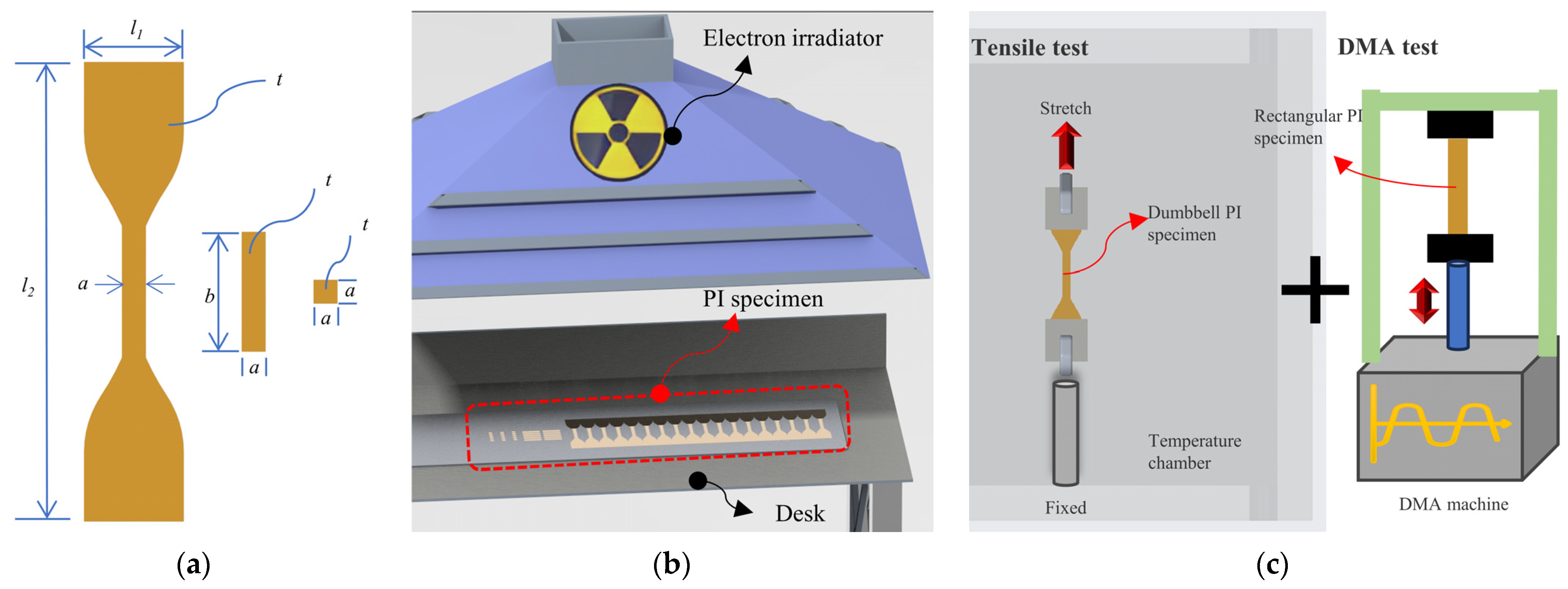


| Shape/Type | Test Type | Dimension (mm) | Quantity/Pieces |
|---|---|---|---|
| Dumbbell | Uniaxial tensile test | l1 = 25; l2 = 115; a = 6; t = 0.05 | 15 |
| Dumbbell | Tensile test with temperature | l1 = 25; l2 = 115; a = 6; t = 0.05 | 35 |
| Rectangular | Dynamic mechanical analysis | a = 6; b = 30; t = 0.05 | 10 |
| Square | AFM surface topography | a = 6; t = 0.05 | 5 |
| Flux | Electron Fluence (e/cm2) | Quantity/Pieces | ||
|---|---|---|---|---|
| Dumbbell | Rectangular | Square | ||
| 1 × 10¹² e/(cm2·s) | 5 × 10¹⁴ | 3 | 2 | 1 |
| 1 × 10¹⁵ | 3 | 2 | 1 | |
| 5 × 10¹⁵ | 3 | 2 | 1 | |
| 1 × 10¹⁶ | 3 | 2 | 1 | |
Disclaimer/Publisher’s Note: The statements, opinions and data contained in all publications are solely those of the individual author(s) and contributor(s) and not of MDPI and/or the editor(s). MDPI and/or the editor(s) disclaim responsibility for any injury to people or property resulting from any ideas, methods, instructions or products referred to in the content. |
© 2023 by the authors. Licensee MDPI, Basel, Switzerland. This article is an open access article distributed under the terms and conditions of the Creative Commons Attribution (CC BY) license (https://creativecommons.org/licenses/by/4.0/).
Share and Cite
Qiu, J.; Ma, J.; Han, W.; Wang, X.; Wang, X.; Heini, M.; Li, B.; Sun, D.; Zhang, R.; Shi, Y.; et al. Effects of Electron Irradiation and Temperature on Mechanical Properties of Polyimide Film. Polymers 2023, 15, 3805. https://doi.org/10.3390/polym15183805
Qiu J, Ma J, Han W, Wang X, Wang X, Heini M, Li B, Sun D, Zhang R, Shi Y, et al. Effects of Electron Irradiation and Temperature on Mechanical Properties of Polyimide Film. Polymers. 2023; 15(18):3805. https://doi.org/10.3390/polym15183805
Chicago/Turabian StyleQiu, Jian, Jusha Ma, Wenjia Han, Xiao Wang, Xunchun Wang, Maliya Heini, Bingyang Li, Dongyang Sun, Ruifeng Zhang, Yan Shi, and et al. 2023. "Effects of Electron Irradiation and Temperature on Mechanical Properties of Polyimide Film" Polymers 15, no. 18: 3805. https://doi.org/10.3390/polym15183805