
Advancing Smart Textiles: Structural Evolution of Knitted Piezoresistive Strain Sensors for Enabling Precise Motion Capture
 ,
,  , , and
Abstract
:1. Introduction
- The knitted pattern in [25] consists of only one elastic yarn, and the influence of inserting the strain sensor in stitch wale or stitch course directions is not analyzed. For this reason, the knitting direction of the sensors is considered as a criterion for selecting the correct sensor design.
- Only a few of the studies presented here investigate the electro-mechanical properties of strain sensors under multi-cyclic mechanical deformation and thereby verify their suitability as strain sensors for motion capture a.o. in medical applications.
2. Materials and Methods
3. Results
3.1. Analysis of Various Piezoresistive Strain Sensors in Stitch Wale and Stitch Course Directions
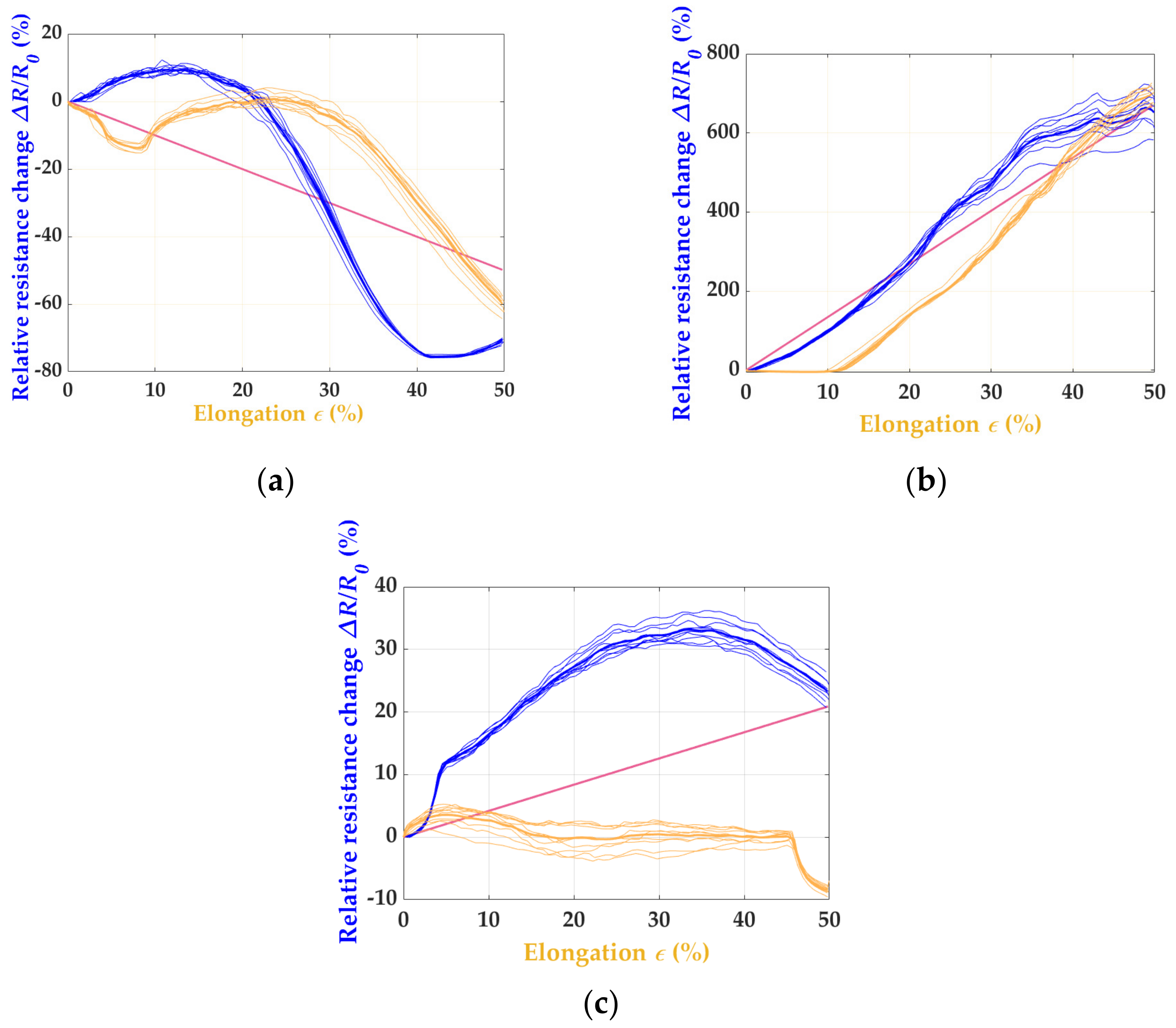
3.2. Analysis of Various Patterns and their Piezoresistive Strain Sensors
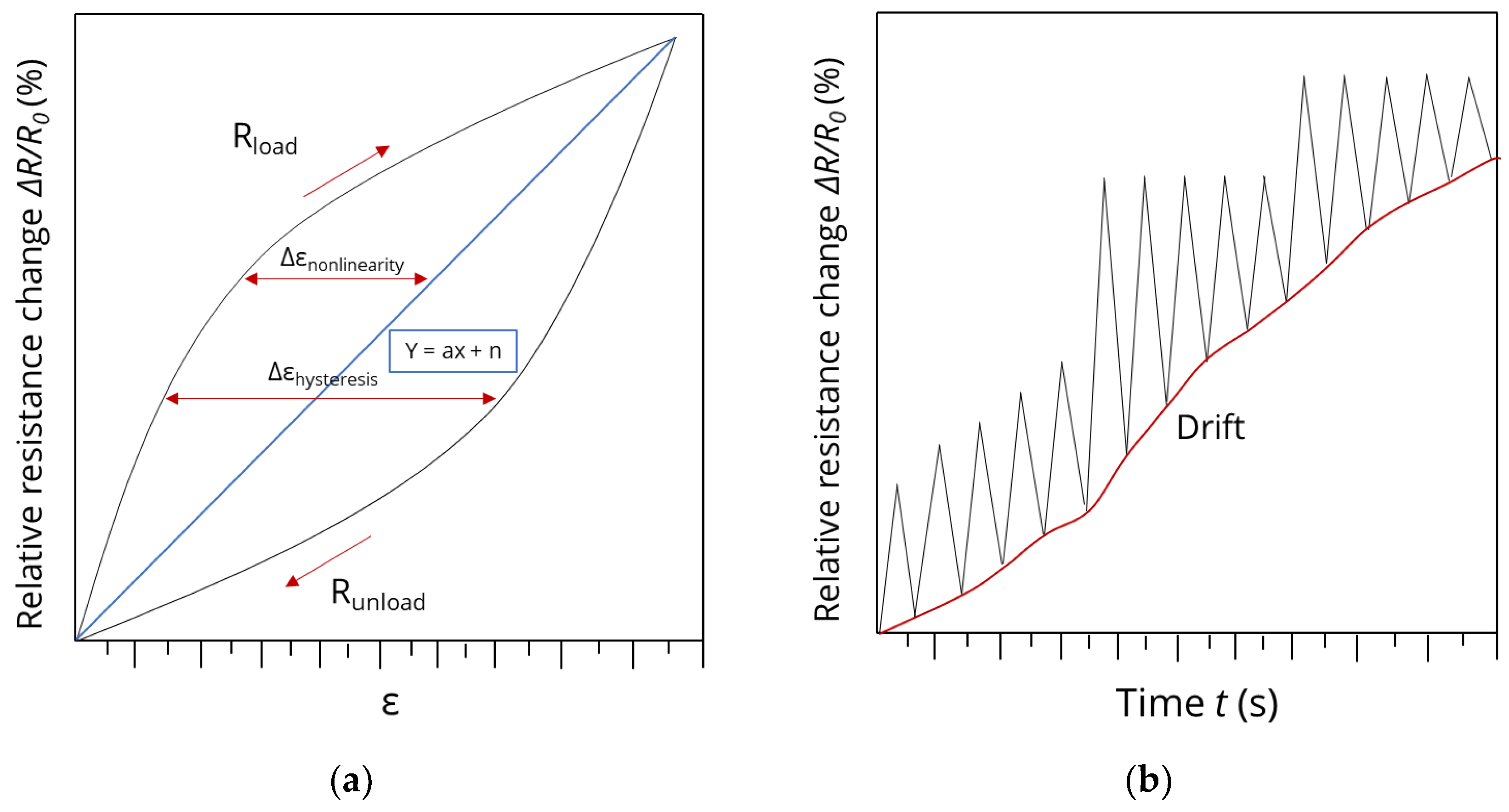
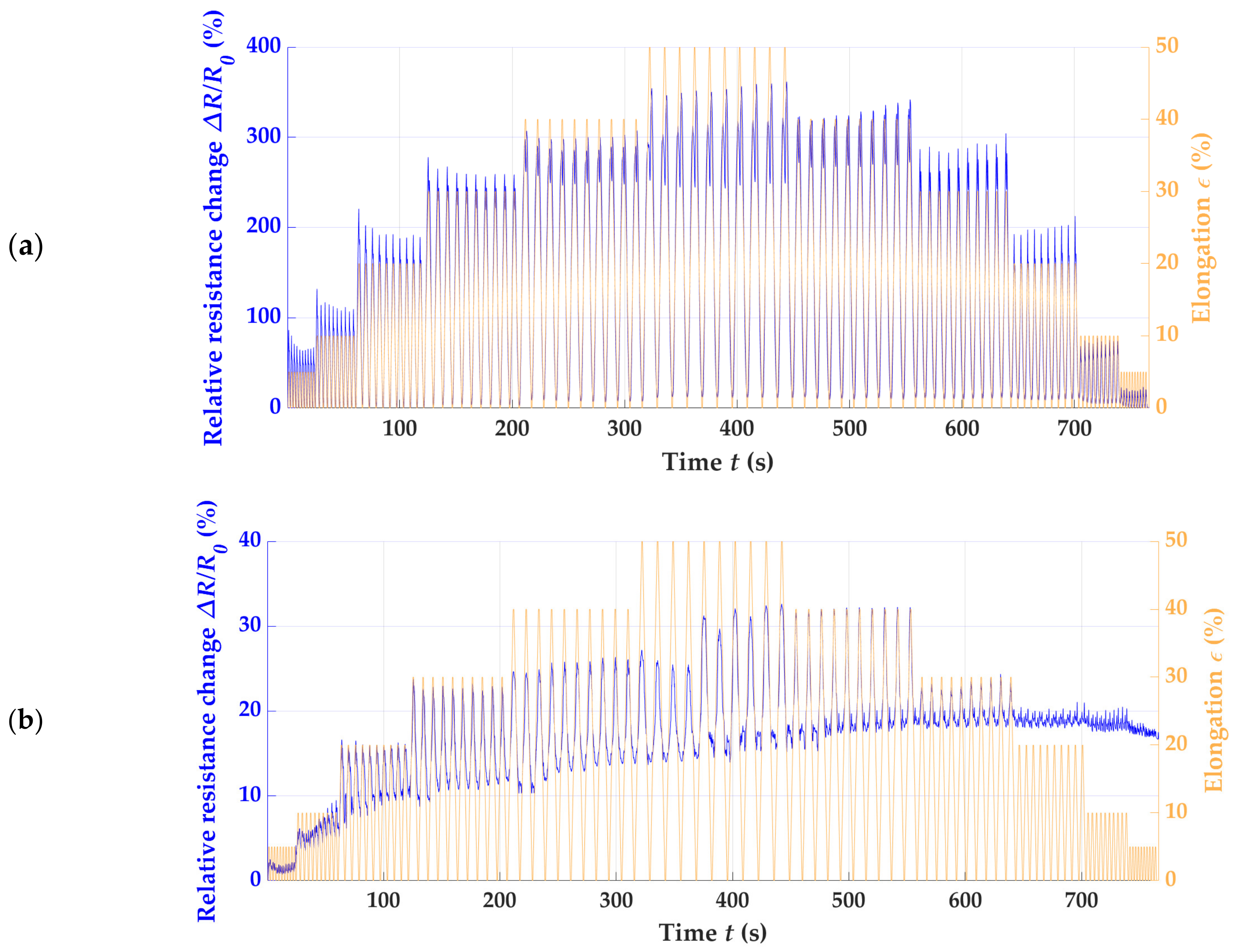
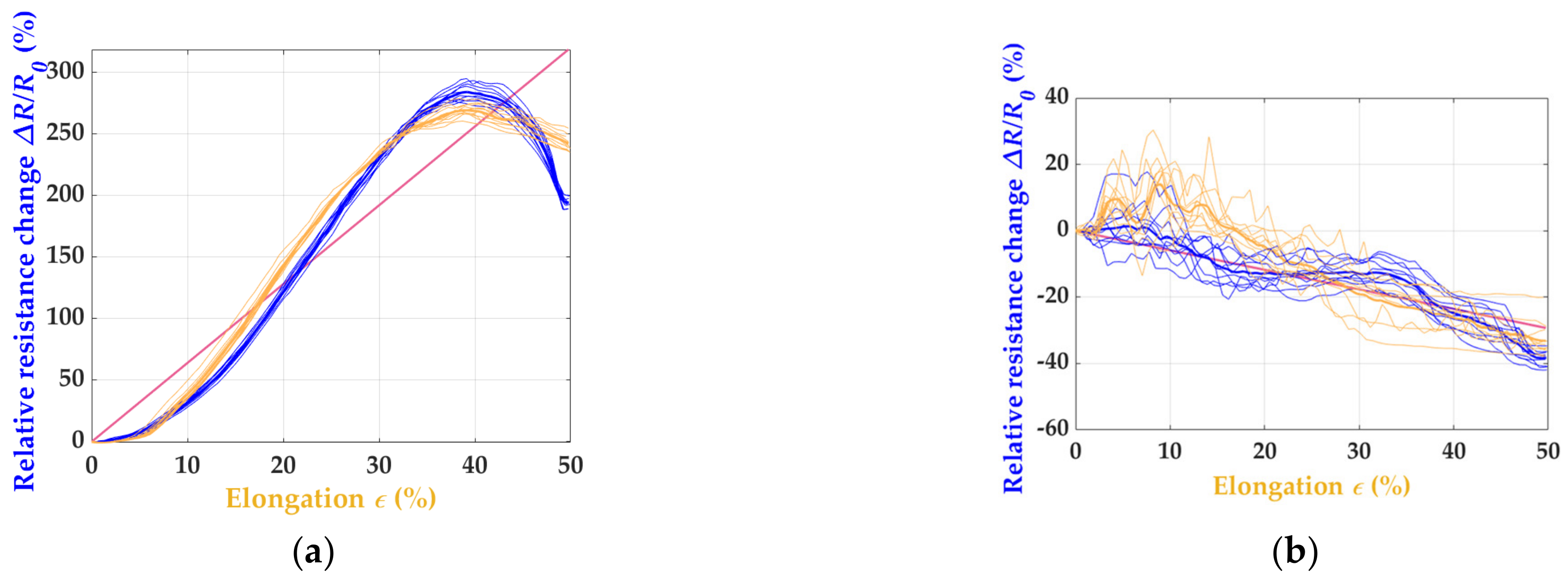
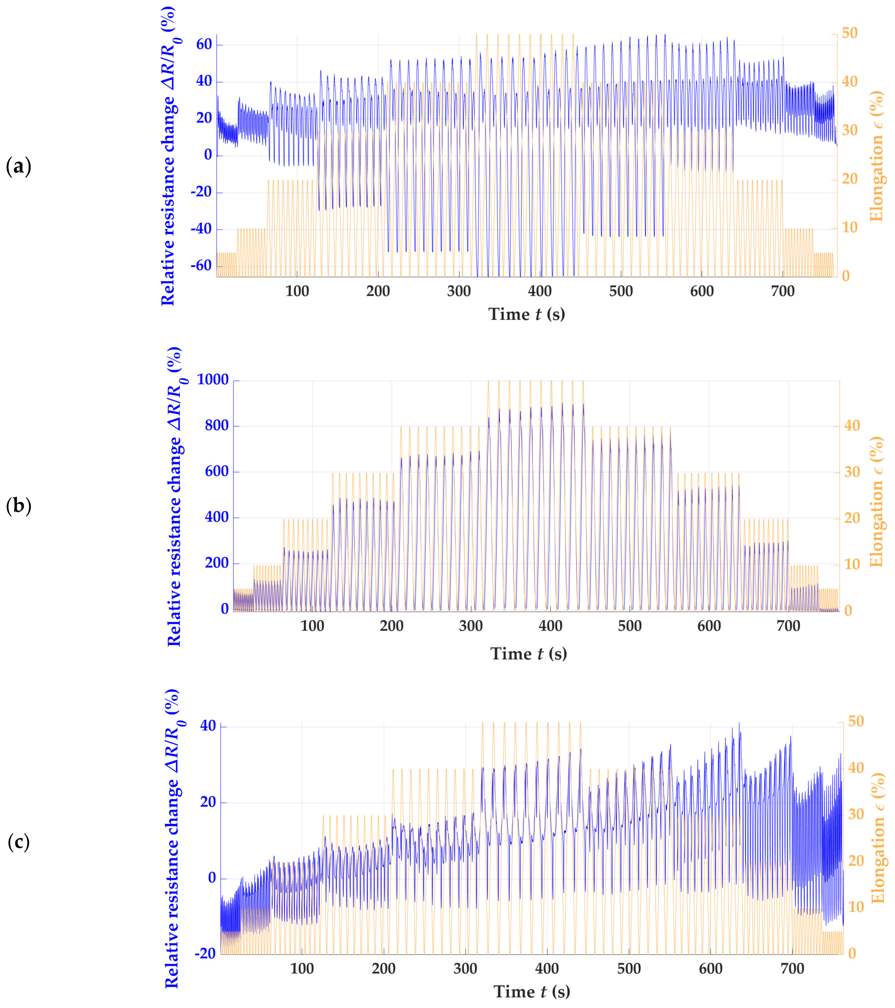
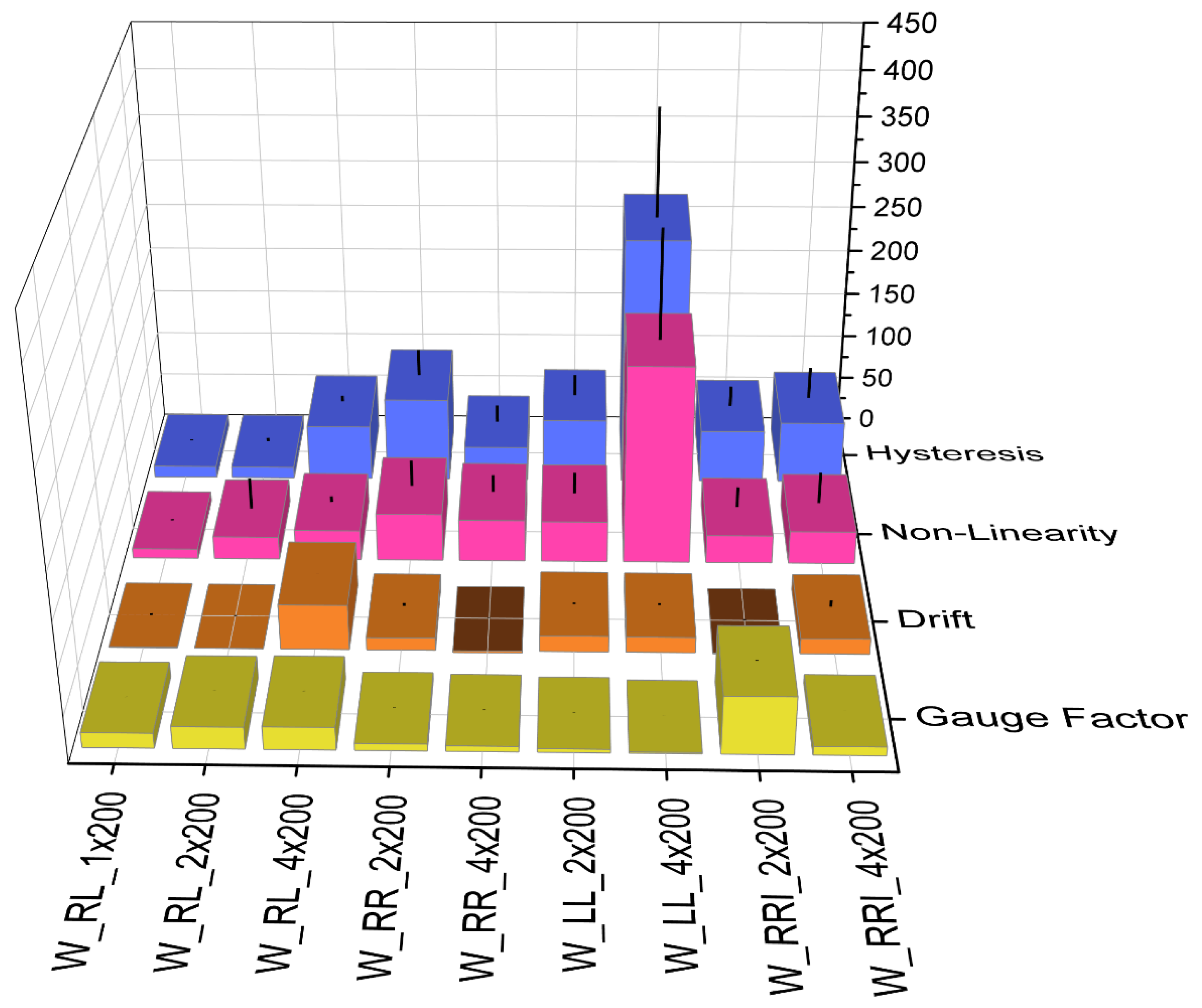
3.3. Analysis of the Nonlinearity, Gauge Factor, Drift, and Hysteresis of Various Patterns and Its Piezoresistive Strain Sensors
4. Discussion
5. Conclusions
Author Contributions
Funding
Institutional Review Board Statement
Data Availability Statement
Conflicts of Interest
References
- Li, M.; Xiong, W.; Li, Y. Wearable Measurement of ECG Signals Based on Smart Clothing. Int. J. Telemed. Appl. 2020, 2020, 6329360. [Google Scholar] [CrossRef] [PubMed]
- Kubicek, J.; Fiedorova, K.; Vilimek, D.; Cerny, M.; Penhaker, M.; Janura, M.; Rosicky, J. Recent Trends, Construction, and Applications of Smart Textiles and Clothing for Monitoring of Health Activity: A Comprehensive Multidisciplinary Review. IEEE Rev. Biomed. Eng. 2022, 15, 36–60. [Google Scholar] [CrossRef] [PubMed]
- Scilingo, E.P.; Gemignani, A.; Paradiso, R.; Taccini, N.; Ghelarducci, B.; de Rossi, D. Performance evaluation of sensing fabrics for monitoring physiological and biomechanical variables. IEEE Trans. Inf. Technol. Biomed. 2005, 9, 345–352. [Google Scholar] [CrossRef] [PubMed]
- Gao, W.; Emaminejad, S.; Nyein, H.Y.Y.; Challa, S.; Chen, K.; Peck, A.; Fahad, H.M.; Ota, H.; Shiraki, H.; Kiriya, D.; et al. Fully integrated wearable sensor arrays for multiplexed in situ perspiration analysis. Nature 2016, 529, 509–514. [Google Scholar] [CrossRef]
- Castano, L.M.; Flatau, A.B. Smart fabric sensors and e-textile technologies: A review. Smart Mater. Struct. 2014, 23, 53001. [Google Scholar] [CrossRef]
- Miller, L.; Mattison, P.; Paul, L.; Wood, L. The effects of transcutaneous electrical nerve stimulation (TENS) on spasticity in multiple sclerosis. Mult. Scler. 2007, 13, 527–533. [Google Scholar] [CrossRef]
- Holleczek, T.; Ru, A.; Harms, H.; Tro, G. Textile pressure sensors for sports applications. In Proceedings of the Sensors, 2010, Waikoloa, HI, USA, 1–4 November 2010; pp. 732–737. [Google Scholar]
- Shu, L.; Hua, T.; Wang, Y.; Qiao Li, Q.; Feng, D.D.; Tao, X. In-shoe plantar pressure measurement and analysis system based on fabric pressure sensing array. IEEE Trans. Inf. Technol. Biomed. 2010, 14, 767–775. [Google Scholar] [CrossRef]
- Xu, W.; Huang, M.-C.; Amini, N.; Liu, J.J.; He, L.; Sarrafzadeh, M. Smart insole: A wearable system for gait analysis. In Proceedings of the 5th International Conference on Pervasive Technologies Related to Assistive Environments, Heraklion, Greece, 6–8 June 2012; pp. 1–4. [Google Scholar]
- Poincloux, S.; Adda-Bedia, M.; Lechenault, F. Geometry and Elasticity of a Knitted Fabric. Phys. Rev. X 2018, 8, 021075. [Google Scholar] [CrossRef]
- Chen, J.; Zhang, J.; Hu, J.; Luo, N.; Sun, F.; Venkatesan, H.; Zhao, N.; Zhang, Y. Ultrafast-Response/Recovery Flexible Piezoresistive Sensors with DNA-Like Double Helix Yarns for Epidermal Pulse Monitoring. Adv. Mater. 2022, 34, e2104313. [Google Scholar] [CrossRef]
- Park, S.Y.; Lee, J.-H. Machine Embroidered Sensors for Limb Joint Movement-Monitoring Smart Clothing. Sensors 2021, 2, 949. [Google Scholar] [CrossRef]
- Kan, C.-W.; Lam, Y.-L. Future Trend in Wearable Electronics in the Textile Industry. Appl. Sci. 2021, 11, 3914. [Google Scholar] [CrossRef]
- Huang, C.-T.; Shen, C.-L.; Tang, C.-F.; Chang, S.-H. A wearable yarn-based piezo-resistive sensor. Sens. Actuators Phys. 2008, 141, 396–403. [Google Scholar] [CrossRef]
- Taccini, N.; Loriga, G.; Pacelli, M.; Paradiso, R. Wearable monitoring system for chronic cardio-respiratory diseases. In Proceedings of the 2008 30th Annual International Conference of the IEEE Engineering in Medicine and Biology Society, Vancouver, BC, Canada, 20–25 August 2008; pp. 3690–3693. [Google Scholar] [CrossRef]
- Amjadi, M.; Kyung, K.-U.; Park, I.; Sitti, M. Stretchable, Skin-Mountable, and Wearable Strain Sensors and Their Potential Applications: A Review. Adv. Funct. Mater. 2016, 26, 1678–1698. [Google Scholar] [CrossRef]
- Xie, J.; Long, H.; Miao, M. High sensitivity knitted fabric strain sensors. Smart Mater. Struct. 2016, 25, 105008. [Google Scholar] [CrossRef]
- Watson, A.; Sun, M.; Pendyal, S.; Zhou, G. TracKnee: Knee angle measurement using stretchable conductive fabric sensors. Smart Health 2020, 15, 100092. [Google Scholar] [CrossRef]
- Ancans, A.; Greitans, M.; Cacurs, R.; Banga, B.; Rozentals, A. Wearable Sensor Clothing for Body Movement Measurement during Physical Activities in Healthcare. Sensors 2021, 21, 2068. [Google Scholar] [CrossRef]
- Liang, A.; Stewart, R.; Bryan-Kinns, N. Analysis of Sensitivity, Linearity, Hysteresis, Responsiveness, and Fatigue of Textile Knit Stretch Sensors. Sensors 2019, 19, 3618. [Google Scholar] [CrossRef]
- Atalay, O.; Tuncay, A.; Husain, M.D.; Kennon, W.R. Comparative study of the weft-knitted strain sensors. J. Ind. Text. 2017, 46, 1212–1240. [Google Scholar] [CrossRef]
- Raji, R.K.; Miao, X.; Zhang, S.; Li, Y.; Wan, A.; Boakye, A. Knitted piezoresistive strain sensor performance, impact of conductive area and profile design. J. Ind. Text. 2020, 50, 616–634. [Google Scholar] [CrossRef]
- Atalay, O.; Kennon, W.R. Knitted strain sensors: Impact of design parameters on sensing properties. Sensors 2014, 14, 4712–4730. [Google Scholar] [CrossRef]
- Molinaro, N.; Massaroni, C.; Lo Presti, D.; Saccomandi, P.; Di Tomaso, G.; Zollo, L.; Perego, P.; Andreoni, G.; Schena, E. Wearable textile based on silver plated knitted sensor for respiratory rate monitoring. In Proceedings of the 2018 40th Annual International Conference of the IEEE Engineering in Medicine and Biology Society (EMBC), Honolulu, HI, USA, 18–21 July 2018; pp. 2865–2868. [Google Scholar] [CrossRef]
- Bozali, B.; Ghodrat, S.; Plaude, L.; van Dam, J.J.F.; Jansen, K.M.B. Development of Low Hysteresis, Linear Weft-Knitted Strain Sensors for Smart Textile Applications. Sensors 2022, 22, 7688. [Google Scholar] [CrossRef] [PubMed]
- Ayodele, E.; Raza Zaidi, S.A.; Scott, J.; Zhang, Z.; Hayajneh, A.; Shittu, S.; McLernon, D. A Weft Knit Data Glove. IEEE Trans. Instrum. Meas. 2021, 70, 3068173. [Google Scholar] [CrossRef]
- Bozali, B.; Ghodrat, S.; Jansen, K.M.B. Development of a Knitted Strain Sensor for Health Monitoring Applications. Eng. Proc. 2023, 30, 10. [Google Scholar]
- Tognetti, A.; Bartalesi, R.; Lorussi, F.; de Rossi, D. Body segment position reconstruction and posture classification by smart textiles. Trans. Inst. Meas. Control 2007, 29, 215–253. [Google Scholar] [CrossRef]
- Lorussi, F.; Galatolo, S.; de Rossi, D.E. Textile-Based Electrogoniometers for Wearable Posture and Gesture Capture Systems. IEEE Sens. J. 2009, 9, 1014–1024. [Google Scholar] [CrossRef]
- Zhao, K.; Niu, W.; Zhang, S. Highly stretchable, breathable and negative resistance variation textile strain sensor with excellent mechanical stability for wearable electronics. J. Mater. Sci. 2020, 55, 2439–2453. [Google Scholar] [CrossRef]
- Abu-Rous, M.; Dabolina, I.; Lapkovska, E. Fabric physical properties and clothing comfort. IOP Conf. Ser. Mater. Sci. Eng. 2018, 459, 12028. [Google Scholar] [CrossRef]
- Deusches Institut für Normung. Textilien und Textile Erzeugnisse—Elektrisch Leitfähige Textilien—Bestimmung des Linea-ren Elektrischen Widerstands von Leiterbahnen (EN 16812:2016); Beuth Verlag Gmbh: Berlin, Germany, 2016. [Google Scholar]
- Bureau International des Poids et Mesures. Evaluation of Measurement Data—Guide to The Expression of Uncertainty in Measurement: GUM 1995 with Minor Corrections. JCGM 2008, 100, 1–116. Available online: https://www.bipm.org/documents/20126/2071204/JCGM_100_2008_E.pdf/cb0ef43f-baa5-11cf-3f85-4dcd86f77bd6 (accessed on 24 August 2023).
- Cherif, C. (Ed.) Textile Materials for Lightweight Constructions: Technologies-Methods-Materials-Properties; Springer: Berlin/Heidelberg, Germany, 2016; ISBN 9783662463413. [Google Scholar]


| Producer | Name | Composition | Linear Density (dtex) | Resistance (Ω·m−1) | Nomenclature |
|---|---|---|---|---|---|
| Gebr. Otto GmbH + Co. KG | TENCEL Lyocell Std. Ringgarn | TENCEL Lyocell | 25 | - | TL |
| Jörg Lederer GmbH Elastic-Garne | Dorlastan 160 DC | Dorlastan/PA 6.6 | 270 | - | EY |
| Amann & Söhne GmbH & Co. KG | Silver-tech + 150 | PA 6.6 | 220 | <300 | SY |
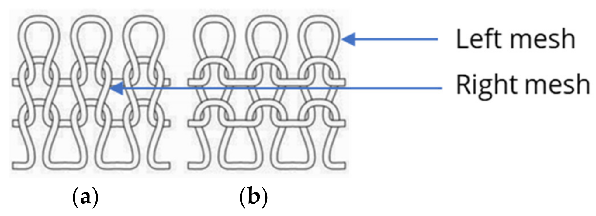
| Knitting Direction | Pattern | Strain Sensor Width (mm) | Strain Sensor Length (mm) | Nomenclature |
|---|---|---|---|---|
| Stitch wale direction | right–left | 1 | 200 | W_RL_1 × 200 |
| Stitch wale direction | right–left | 2 | 200 | W_RL_2 × 200 |
| Stitch wale direction | right–left | 4 | 200 | W_RL_4 × 200 |
| Stitch wale direction | right–right | 2 | 200 | W_RR_2 × 200 |
| Stitch wale direction | right–right | 4 | 200 | W_RR_4 × 200 |
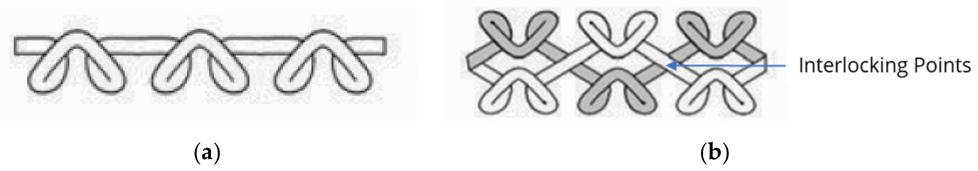
| Stitch wale direction | right–right–interlock | 2 | 200 | W_RRI_2 × 200 |
| Stitch wale direction | right–right–interlock | 4 | 200 | W_RRI_4 × 200 |
| Stitch wale direction | left–left | 2 | 200 | W_LL_2 × 200 |
| Stitch wale direction | left–left | 4 | 200 | W_LL_4 × 200 |
| Stitch course direction | right–left | 200 | 2 | C_RL_2 × 200 |
| W_RL_2 × 200 | W_RR_2 × 200 | W_LL_2 × 200 | W_RRI_2 × 200 | C_RL_2 × 200 | |
|---|---|---|---|---|---|
| Face side |  |  |  |  | 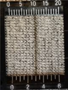 |
| Reverse side | 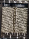 | 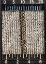 |  | 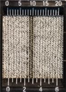 | 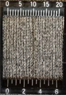 |
| Parameter | |
|---|---|
| Clamping length | 200 mm |
| Preload | 0.5 N |
| Testing speed | 1000 mm/min |
| Strain in the range from | 0% to 5%, 0% to 10%, 0% to 20%, 0% to 30%, 0% to 40%, 0% to 50% and 50% to 0%, 40% to 0%, 30% to 0%, 20% to 0%, 10% to 0%, 5% to 0%, |
| Release control | elongation limits |
| No. of cycles | 10 |
Disclaimer/Publisher’s Note: The statements, opinions and data contained in all publications are solely those of the individual author(s) and contributor(s) and not of MDPI and/or the editor(s). MDPI and/or the editor(s) disclaim responsibility for any injury to people or property resulting from any ideas, methods, instructions or products referred to in the content. |
© 2023 by the authors. Licensee MDPI, Basel, Switzerland. This article is an open access article distributed under the terms and conditions of the Creative Commons Attribution (CC BY) license (https://creativecommons.org/licenses/by/4.0/).
Share and Cite
Warncke, M.N.; Böhmer, C.H.; Sachse, C.; Fischer, S.; Häntzsche, E.; Nocke, A.; Mersch, J.; Cherif, C. Advancing Smart Textiles: Structural Evolution of Knitted Piezoresistive Strain Sensors for Enabling Precise Motion Capture. Polymers 2023, 15, 3936. https://doi.org/10.3390/polym15193936
Warncke MN, Böhmer CH, Sachse C, Fischer S, Häntzsche E, Nocke A, Mersch J, Cherif C. Advancing Smart Textiles: Structural Evolution of Knitted Piezoresistive Strain Sensors for Enabling Precise Motion Capture. Polymers. 2023; 15(19):3936. https://doi.org/10.3390/polym15193936
Chicago/Turabian StyleWarncke, Mareen N., Carola H. Böhmer, Carmen Sachse, Susanne Fischer, Eric Häntzsche, Andreas Nocke, Johannes Mersch, and Chokri Cherif. 2023. "Advancing Smart Textiles: Structural Evolution of Knitted Piezoresistive Strain Sensors for Enabling Precise Motion Capture" Polymers 15, no. 19: 3936. https://doi.org/10.3390/polym15193936