Abstract
Strontium-doped calcium phosphate/chitosan films were synthetized on silicon substrates using the radio-frequency magnetron sputtering technique and the matrix-assisted pulsed laser evaporation technique. The deposition conditions associated with the radio-frequency magnetron sputtering discharge, in particular, include the high temperature at the substrate, which promotes the formation of strontium-doped tetra calcium phosphate layers. The physical and chemical processes associated with the deposition of chitosan on strontium-doped calcium phosphate layers were investigated using Fourier Transform Infrared Spectroscopy, Energy Dispersive X-ray Spectroscopy, and Scanning Electron Microscopy. Mass spectrometry coupled with laser induced ablation of the composite films proved to be a useful tool in the detection of the molecular ions characteristic to chitosan chemical structure.
1. Introduction
Calcium phosphates (CaPs) have been intensely studied for their biomedical applications. Examples of CaPs are: dicalcium phosphate anhydride [DCPA; CaHPO4; Ca/P = 1], dicalcium phosphate dehydrate [DCPD; CaHPO4 × 2 H2O; Ca/P = 1], octacalcium phosphate [OCP; Ca8(HPO4)2(PO4)4 × 5 H2O; Ca/P = 1.33], α- and β-tricalcium phosphate [α-TCP and β-TCP; Ca3(PO4)2; Ca/P = 1.5], tetra calcium phosphate [TTCP; Ca4(PO4)2O; Ca/P = 2], and hydroxyapatite [Hap; Ca10(PO4)6(OH)2; Ca/P = 1.67]. Among them, HAp is the main mineral phase in solid tissues. Biological HAp is calcium deficient [CDHA; Ca10-x(HPO4)x(PO4)6-x(OH)2-x, 0 ≤ x ≤ 1; Ca/P = 1.5–1.67] and carbonate (CO32−) substituted [1]. Several vicarious ions such as Mg2+ (0.60–0.72 wt%), Sr2+ (0.00–0.05 wt%), Zn2+ (0.00–39.00 ppm), Cl− (0.1–0.13), F− (0.03–0.10 wt%), Na+ (0.9–1.00 wt%), K+(0.03–0.07 wt%), and CO32− (4.8–7.40 wt%) are present in bone apatites [2].
Synthetic HAp can be obtained using different methods: dry (solid state and mechanochemical), wet (chemical precipitation, hydrothermal, hydrolysis, sol-gel, emulsion, and sonochemical), and high-temperature (combustion and pyrolysis), or a combination of these. Each synthesis technique has its advantages and disadvantages, which influence the properties of the final product (e.g., morphology, phase composition, crystallinity, mechanical, and biological properties, etc.). The hydrothermal synthesis of HAp implies the use of an aqueous solution containing the calcium and phosphate precursors, which is sealed in a reaction vessel and subjected to a high-temperature and high-pressure treatment [3,4,5]. The microwave assisted hydrothermal synthesis uses microwaves for heating, compensating for the drawback of temperature unevenness characteristic of hydrothermal synthesis [6,7].
HAp coatings can be obtained via several deposition techniques such as electrochemical [8,9] and electrophoretic [10] depositions, dip coating [11], biomimetic coating [12], plasma spraying [13], flame spraying [11], electron beam physical vapor deposition [14], pulsed laser deposition [15], chemical vapor deposition [14], or radio frequency magnetron sputtering [16]. The advantages and drawbacks of these methods, including cost-and time-efficiency, uniformity of the layer, layer thickness, the ability to cover complicated shapes, and/or additional pre- and post-treatment requirements, must be considered before choosing a specific coating technique for a desired application [11].
HAp can be substituted with anionic and cationic ions. Anionic substitution occurs at the PO43− (e.g., CO32−, SiO44−, SO42−) or OH− (e.g., CO32−, Cl−, F−, Br−) sites, while cationic substitution occurs at the Ca2+ site (e.g., bivalent cations: Sr2+, Mg2+, Zn2+; monovalent cations: Ag+, Na+, K+) [2,17,18].
HAp is a stable calcium phosphate with a Ca/P ratio equal to 1.67. The most common form of HAp is the hexagonal phase in the P63/m space group. The ions in the HAp lattice (Ca2+, PO43−, and OH−) are arranged in two symmetric parts of the unit cell. A unit cell contains 10 Ca2+ ions, from which four Ca2+ ions type I [Ca(I)—arranged in columns parallel to the OH− channels and the c-axis], six Ca2+ type 2 [Ca(II)—arranged in a triangular array], 6 PO43− (tetrahedron) ions, and two OH− ions can be found. The Ca(I) is bonded to nine oxygen atoms (belonging to 6 PO43−). Six of these bonds are strong and three are weaker, with a Ca(I)-O bond length of 0.255 nm. The Ca(II) is bonded to seven oxygen atoms (belonging to 5 PO43− and OH−), with a Ca(II)-O bond length of 0.245 nm [2,17,18,19,20].
Strontium substitution influences the biological properties of HAp, promoting the osteoblast differentiation and proliferation, the alkaline phosphatase (ALP) activity, and the production of collagen type I, decreasing the osteoclast activity, and improving the antimicrobial activity against Lactobacillus, Staphylococcus aureus, and Escherichia coli [2]. Strontium substitution occurs at both calcium sites, Ca(I) and Ca(II), considering their similar ionic radius: 1.00 Å for Ca2+ and 1.18 Å for Sr2+. At low Sr concentrations (1.00–3.5 at.%) the Ca(I) substitution is favored, while at higher concentrations (5 at.%) Ca(II) substitution is preferred [2,21].
Radio frequency magnetron sputtering (RF-MS) discharge is a plasma technique used to deposit various materials on different substrates [22]. The plasma processes involve the bombardment of a sputtering target by energetic ions created in the discharge plasma. The process causes the removal of the target atoms or ions which further are deposed on a substrate as a thin film. The secondary electrons emitted from the target play an important role in maintaining the plasma and in the formation of the coating chemical structure [23]. The advantages of this technique are the good adhesion between the substrate and film, the control of the film chemical composition, the control of temperature during the deposition process, and the control of the uniformity and density of the coatings [24]. The coating composition depends on the discharge power, the deposition time, and the thickness of the film [22].
Matrix Assisted Pulsed Laser Evaporation (MAPLE) is a laser assisted deposition technique which involves the evaporation of a frozen target that consists of a delicate compound dissolved in a volatile solvent. The deposition mechanism implies the fact that the solvent initially absorbs the laser energy, thus preventing the molecules of interest from being damaged by the laser radiation. Further, by continuous laser energy absorbing, the solvent evaporates, and the target molecules are transferred to the substrate and placed in the way of molecular movement, forming a nucleation center, thus the thin film is formed layer by layer. Moreover, due to a low adhesion coefficient, the solvent molecules are pumped away by the pumping system [22,25].
Among other compounds of CaPs, TTCP has the highest Ca/P ratio and it was also obtained as coatings from plasma and laser deposition techniques. Its solubility is higher than that of HAp and it is a biodegradable and biocompatible CaP. It can easily hydrolyse to HAp in humid or aqueous environments, which is why it can only be obtained in dry-air or vacuum environments. As a biomaterial, it is usually used as bone cement [26,27,28].
Mass spectrometry (MS) is an analytical method used for the detection of chemical compounds by measuring the intensities of the collected ions as a function of the mass-to-charge ratio [29]. The recording of the mass spectra after the laser induced ablation (LIA-QMS) of a coating layer allows the detection with high sensitivity of its chemical structure.
This work reports on the synthesis of strontium-doped calcium phosphate (CaPSr)/chitosan films by coupling a plasma deposition technique and a laser evaporation technique. We characterized the films using the following spectral methods: Fourier Transform Infrared Spectroscopy, Energy Dispersive X-ray Spectroscopy, and LIA-QMS, which reveal the processes associated to the chemical and physical structure of the composite layers as function of the deposition conditions. The morphologies of layers were investigated using Scanning Electron Microscopy (SEM).
2. Materials and Methods
2.1. Materials
Si samples (10 × 10 mm2), with a thickness of 2 mm, were used as substrates.
Calcium nitrate tetrahydrate [Ca(NO3)2·4H2O; Sigma-Aldrich; CAS number: 13477-34-4; Molecular weight: 236.15 g/mol], diammonium hydrogen phosphate [(NH4)2HPO4; Fulka; CAS number: 7783-28-0; Molecular weight: 132.06 g/mol], and strontium nitrate [Sr(NO)3; 211.63 g/mol] were used as precursors for Ca2+, PO43−, and Sr2+, respectively. Ammonium hydroxide [NH4OH; 35.04 g/mol] was used to adjust the pH of the solution.
Low molecular weight chitosan (C12H24N2O9; Sigma-Aldrich, St. Louis, MO, USA; CAS number: 9012-76-4; Molecular weight: 50,000–190,000 Da; Source: shrimp shells; Deacetylation degree: 75–85%) was used to prepare the targets for the MAPLE deposition. The chemical structure is presented in Figure 1.
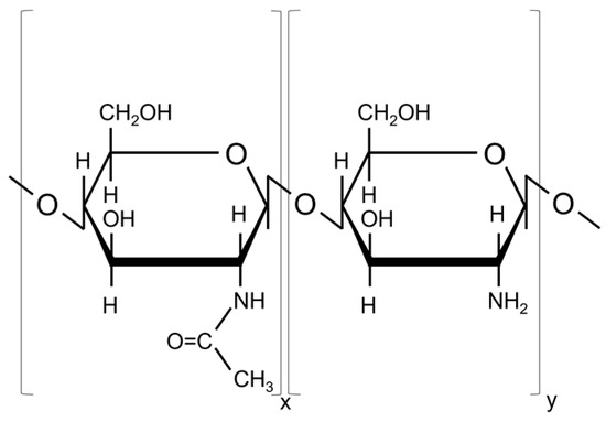
Figure 1.
Chemical structure of chitosan (N-acetyl glucosamine and glucosamine units).
2.2. Synthesis Technique
Microwave-Assisted Hydrothermal Synthesis of Sr-Doped Hydroxyapatite
The 3% strontium-doped hydroxyapatite (HApSr; theoretical formula: Ca9.7Sr0.3(PO4)6(OH)2) was synthetized using microwave-assisted hydrothermal synthesis. Two aqueous solutions of Ca(NO3)2 + Sr(NO3)2 and (NH4)2HPO4, respectively, were obtained by dissolving, under continuous stirring, the proper amount of the precursors in distilled water in order to keep the Sr/(Ca + Sr) molar ratio equal to 0.03, and the (Ca+ Sr)/P molar ratio equal to 1.67. The (NH4)2HPO4 solution was added dropwise to the Ca(NO3)2 + Sr(NO3)2 solution under continuous stirring using a peristaltic pump set to 50 rpm. The pH of the final solution was adjusted to 10 using NH4OH. The hydrothermal synthesis was conducted using the Milestone synthWAVE microwave synthesis system. The solution was heated to 200 °C for 15 min, and maintained at this temperature for 30 min, while the pressure was set to 16 bar. After the synthesis, the equipment was cooled and depressurized. The precipitate was washed with distilled water three times using centrifugal equipment (6000 rpm, 10 min) and dried at 50 °C. After drying, the white powder was mechanically pressed and sputtering targets with diameters of 5 cm and thickness of 4 mm were prepared.
2.3. Deposition Techniques
2.3.1. Sr-Substituted Calcium Phosphate Deposition by Radio-Frequency Magnetron Sputtering
The CaPSr layers were deposited on Si substrates using the RF-MS technique, with a magnetron plasma source purchased from K.J. Lesker Company (Jefferson Hills, PA, USA). The depositions were conducted in Ar gas flow (6 mln/min), at a working power of 100 W and a working pressure of ~10−2 mbar (base pressure ~10−5), for 10 h. The distance between the substrate holder and the magnetron head was set to ~8.5 cm. The thickness of the CaPSr layers is about 300 nm and was calculated after the measurement of the deposition rate [22].
The temperature at the substrate during the deposition process was measured using a single ended thermocouple probe (acquired from K.J. Lesker Company) placed on the substrate surface. After a deposition process of 10 h, it reaches the value of about 200 °C from 25 °C room temperature. The increase of the temperature from 25 °C to 200 °C is due to the energy of particles that attain the substrate: atoms sputtered from the target, argon atoms reflected from the target, and secondary electrons from the target [30].
A homemade electronically controlled oven was used for additional heat for the substrate holder during RF-MS deposition from room temperature (25 °C) (CaPSr_1) up to 100 °C (CaPSr_2) and 400 °C (CaPSr_3). These values were measured when plasma was stopped. The results show that the temperature of the substrate during the deposition process varies between 225 and 600 °C. The RF-MS experimental setup schematic representation was previously reported in ref. [22].
2.3.2. Chitosan Deposition by Matrix-Assisted Pulsed Laser Evaporation
The chitosan targets were prepared using a 2% chitosan solution. The chitosan powder was mixed with distilled water under continuous magnetic stirring for 6 h. Acetic acid (200 µL) was also added during the stirring period for complete chitosan dissolution. The MAPLE targets were frozen in liquid N2. A KrF* excimer laser source (COMPexPro 205 Lambda Physics-Coherent, λ = 248 nm, τFWHM = 25 ns, Coherent, Santa Clara, CA, USA) was used for the MAPLE depositions. The experiments were conducted at room temperature, at a pressure of 0.1 Pa inside the deposition chamber, under a laser fluence of 300 mJ/cm2, and a laser repetition rate of 10 Hz. The substrate-to-target distance was set to 5 cm. During the deposition, the target was rotated to avoid drilling and its temperature was lowered by adding liquid N2 into the cooling system. The chitosan layers were deposited onto the CaPSr-coated Si substrates. The MAPLE experimental setup schematic representation was previously reported in ref. [22].
2.4. Characterization Techniques
The surface morphology was evaluated using Scanning Electron Microscopy (SEM) and the elemental composition using Energy Dispersive X-ray Spectroscopy (EDX) with a ThermoFisher Apreo S Scanning Electron Microscope (1.3 × 10⁻³ Pa and 8 kV, Waltham, MA, USA) and a SiLi EDX detector.
The Fourier Transform Infrared Spectroscopy (FTIR) was used for analyzing the molecular structure of CaPSr and CaPSr_CS layers. The ATR-FTIR spectra were acquired in the range of 4000–400 cm−1, with a 4 cm−1 resolution, using a Perkin-Elmer SP 100 FTIR spectrometer. The IR transmission spectra were transformed into absorption spectra using the SPECTRUM software(version 6.3.5.0176), while the curve-fitting of the spectra was performed using the MagicPlotPro software (version 2.9), as described in ref. [31].
The chitosan contained in the CaPSr_CS samples produced in different experimental conditions was structurally and chemically evidenced by laser induced ablation (LIA) of the layers. The species expelled from the layers were analyzed using Quadrupole Mass Spectrometry (QMS). Details on the working procedure and set-up are presented in ref. [32]. A Q-switched laser source was used during the experiments. The laser parameters were the following: pulse repetition rate of 1 kHz, 1053 nm wavelength, 10 ns pulse duration, 350 μJ pulse energy, and 31 J/cm2 laser fluence in the focal spot on the target surface. The laser beam profile has a Gaussian shape and the experiments were conducted at an ambience temperature of 16 °C [32]. The mass spectrometer (Pfeiffer QMG 220, Pfeiffer Vacuum, Aßlar, Germany) collected the currents of the following ions characteristic to CaPSr, chitosan, and Si substrate: Si+ (m/q = 28), Ca+ (m/q = 40), P+ (m/q = 31), O+ (m/q = 16), C+ (m/q = 12), N+ (m/q = 14), CaOH+ (m/q = 57), PO4+ (m/q = 95), C6H11+ (m/q = 83), NHCOCH3+ (m/q = 58), C5H5O+ (m/q = 81), Sr+ (m/q = 87.6), CaSr+ (m/q = 127.6), SrOH+ (m/q = 104.6), and C6H11NO4+ (m/q = 161), as a function of time. The Multiple Ions Detection (MID) working mode of the mass spectrometer was used to acquire the data (time resolution 5 ms ± 5%). The Sr+, CaSr+ and C6H11NO4+ ions were not identified during the QMS analysis.
3. Results
3.1. Scanning Electron Microscopy
The surface morphology of the CaPSr layers deposited on Si substrates is presented in Figure 2.
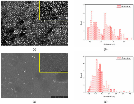
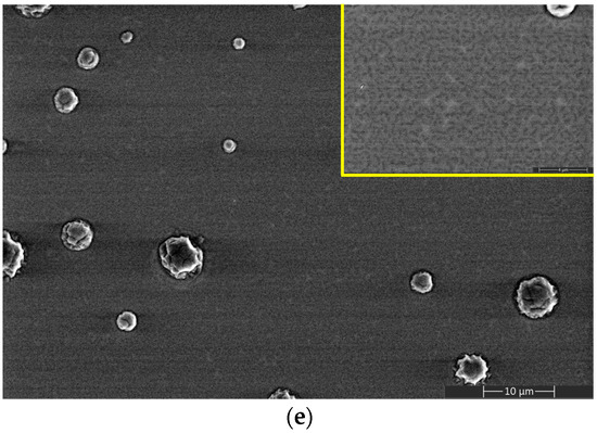
Figure 2.
SEM image of CaPSr_1 (a), CaPSr_2 (c), and CaPSr_3 (e) and grain size distribution of CaPSr_1 (b) and CaPSr_2 (d).
By controlling the temperature of the Si substrate during the RF-MS deposition, CaPSr layers with different surface morphologies were obtained (Figure 2).
A grain-like structure was identified for the CaPSr coating surfaces deposited at room temperature (Figure 2a) and 100 °C (Figure 2c), the grain sizes ranged between 0.4–2.3 μm (Figure 2b), and 0.1–0.8 μm (Figure 2d), respectively. As the temperature of the substrate is oven increased from 25 °C to 100 °C, the grain sizes decrease, and their morphologies change from irregular shapes to quasi-spherical shapes (Figure 2a,c). At the 100 °C substrate temperature, zones where the CaPSr layer partially exfoliates (Figure 2c) were observed. At the substrate temperature of 400 °C, the SEM images (Figure 2e) reveal no grain formation, only microchannels structures, which is possibly due to the coalescence of the grains. As the temperature of the substrate increases, the deposited atoms or molecules gain more thermal energy, migrate to the surface, and rearrange. A similar topography of CaP layers deposited by radio frequency magnetron sputtering technique was also obtained by Bramowicz et al. [33].
Additionally, some spherical structures with diameters ranging between 1 and 7 μm were observed (see Figure 2e). This surface morphology may be caused by the blistering of the layers after the end of the deposition procedure, during the cooling of the substrate holder. The mismatch between the thermal conductivity of the Si substrate and the deposited layers usually produces such effects.
The morphology of the chitosan layer deposited by MAPLE on the Si substrate is presented in Figure 3a. During the MAPLE deposition of the chitosan layer some spherical particles, ranging between 0.3 and 0.7 μm in diameter, were formed. Such structures appear due to the splashing of chitosan during laser evaporation [34].
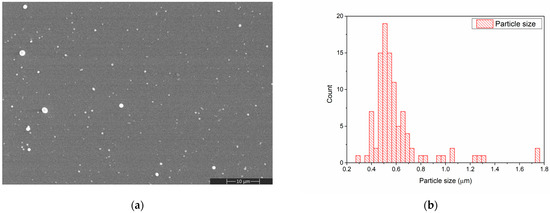
Figure 3.
SEM image of CS deposited on Si substrate (a) and CS particle size distribution determined from the SEM image (b).
The morphology of the CaPSr layers (Figure 2a,c,e) is changed after the chitosan deposition (Figure 4a,c,e). The embedding of chitosan during the MAPLE deposition into the CaPSr layers is confirmed by the SEM images. After chitosan deposition onto the CaPSr layers is obtained at substrate temperatures of 25 °C (CaPSr_CS_1) and 100 °C (CaPSr_CS_2), the edges of the grains are smother (Figure 4a,c) compared to those observed for the corresponding CaPSr layers: CaPSr_1 and CaPSr_2 (Figure 2a,c). These findings confirm that chitosan was embedded between the CaPSr grains. Moreover, the changes in the grain size distribution (Figure 2b,d and Figure 4b,d) sustain the above ascertainment. The thicknesses of the layers increased following the chitosan deposition, with lower values for CaPSr_CS_1, ~370 nm, and higher values for CaPSr_CS_2, ~398 nm. These results may indicate a deeper embedding of the chitosan layer into the CaPSr coating deposited without oven-controlled heating of the substrate. The embedding of chitosan into the CaPSr layer deposited at a substrate temperature of 400 °C is evidenced by the SEM images, as the microchannels observed for CaPSr_3 (Figure 2e) were no longer observed for CaPSr_CS_3 (Figure 4e). However, the cross-sectional SEM images (not showed here) evidenced that the chitosan was mainly deposited at the surface as microparticles, leading to a layer thickness of up to ~700 nm. These results are sustained by our previous research [22] in which calcium phosphate/chitosan composite layers were obtained on Ti samples using the RF-MS and MAPLE techniques. As the temperature of the substrate was increased, the CaP layers became more compact and chitosan was mainly deposited at the surface of the samples. Chitosan microparticles were also observed in the SEM images for the CaPSr_CS layer surfaces.
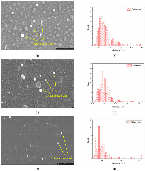
Figure 4.
SEM image of CaPSr_CS_1 (a), CaPSr_CS_2 (c), and CaPSr_CS_3 (e) and grain size distribution of CaPSr_CS_1 (b), CaPSr_CS_2 (d), and CaPSr_CS_3 (f).
3.2. Energy Dispersive X-ray Spectroscopy
The specific chemical elements in CaPSr (Ca, P, O, Sr), along with Si, characteristic of the substrate, were identified in all the EDX spectra of the CaPSr coatings. The atomic ratios for the HApSr powder obtained through the Microwave-assisted Hydrothermal synthesis, calculated from the EDX measurements, are 1.70 for the (Ca + Sr)/P ratio and 0.024 for the Sr/(Ca + Sr) ratio. The slightly lower Sr/(Ca + Sr) ratio may indicate that part of the Sr ions remained in the solution during the synthesis [35].
The EDX spectrum of the CaPSr_1 coating is presented in Figure 5.
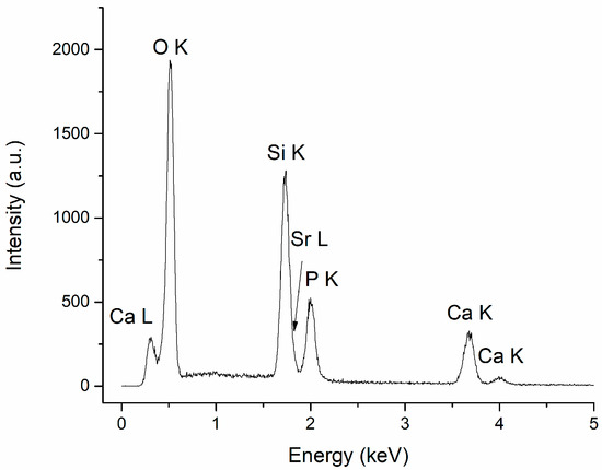
Figure 5.
EDX spectrum of CaPSr_1.
The atomic ratios for (Ca + Sr)/P and Sr/(Ca + Sr) calculated for the CaPSr coatings, following the EDX measurements, are presented in Table 1. The (Ca + Sr)/P ratios are similar for all coatings (~2), regardless of the substrate temperature, as an indication of Sr-doped TTCP. We suppose that the high temperature from the substrate during the deposition process does not allow the incorporation of hydroxyl groups in the apatite structure, which is essential for the recovery of the Sr-doped HAp structure on the substrate. It is known that, during the RF magnetron sputtering deposition, HAp decomposition may appear, leading to TTCP formation, which increases the Ca/P ratio [27].

Table 1.
EDX (Ca + Sr)/P and Sr/(Ca + Sr) atomic ratios for the CaPSr coatings.
The Sr/(Ca + Sr) ratio has the lowest value for the CaPSr coating deposited without oven heating of the substrate during the RF-MS deposition (CaPSr_1) and the highest value for the CaPSr coating deposited at a substrate temperature of 100 °C. The Sr/(Ca + Sr) atomic ratio calculated for the CaPSr coating deposited without oven heating of the substrate (0.030 ± 0.003) was the closest to the theoretical value of 0.03.
The specific chemical elements in CaPSr (Ca, P, O, Sr) and chitosan (C, N), along with Si, characteristic of the substrate, were identified in all the EDX spectra of the CaPSr_CS coatings. The EDX spectrum of the CaPSr_CS_1 is presented in Figure 6.
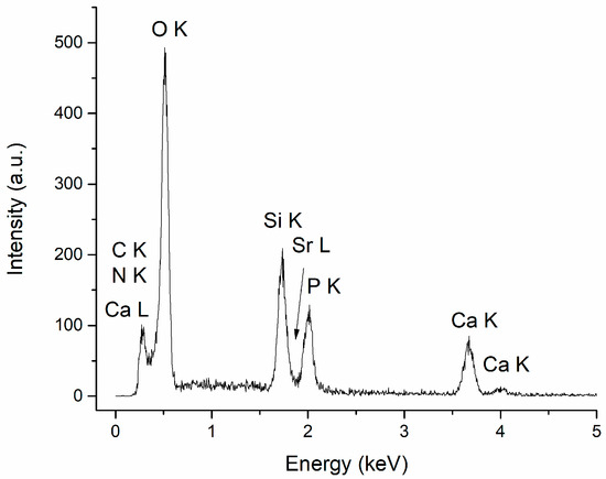
Figure 6.
EDX spectrum of CaPSr_CS_1.
The atomic ratios for the CaPSr_CS coatings, calculated from the EDX measurements, are presented in Table 2. The (Ca + Sr)/P ratios for the coatings deposited without oven-controlled heating of the substrate (CaPSr_CS_1) and by oven heating of the substrate at 100 °C (CaPSr_CS_2) are similar to those reported for the CaPSr coatings without CS (CaPSr_1 and CaPSr_2, respectively). For the coating deposited at a substrate temperature of 400 °C, the (Ca + Sr)/P ratio decreased from 2.09 ± 0.05 for the CaPSr coating to 1.76 ± 0.04 for the CaPSr_CS coating.

Table 2.
EDX (Ca + Sr)/P and Sr/(Ca + Sr) atomic ratios for the CaPSr_CS coatings.
3.3. Fourier Transform Infrared Spectroscopy
The FTIR analysis was required in order to identify the chemical groups characteristic of CaPSr and CaPSr_CS. The main functional group that manifests vibrations specific to the doped or undoped CaP is PO43−. In CaP, the P-O bonds’ vibration frequencies in the PO43− group are identified as: 1120–1000 cm−1 (ν3), 960 cm−1 (ν1), 600–550 cm−1 (ν4), and 470 cm−1 (ν2) [1,36]. There are several papers that have previously indicated that the doping of calcium phosphate compounds or their formation in multiple physical states (α-TCP and β-TCP, Ca3(PO4)2, Ca/P = 1.5; TTCP, Ca4(PO4)2O, Ca/P = 2; CaHPO4, Ca/P = 1; CaHPO4 × 2 H2O, Ca/P = 1; Ca8(HPO4)2(PO4)4 × 5 H2O, Ca/P = 1.33) leads to the occurrence of P-O bond vibrations at certain wavenumbers.
Figure 7 presents the FTIR spectra of the CaPSr coatings deposited on Si at different substrate temperatures in the wavenumber range of 1200–500 cm−1. We did not observe absorption bands at 3570 cm−1 (characteristic of the stretching mode of the OH group in the lattice water), and 1640 cm−1 (characteristic of the bending mode of the OH group in the water adsorbed on the film surface).
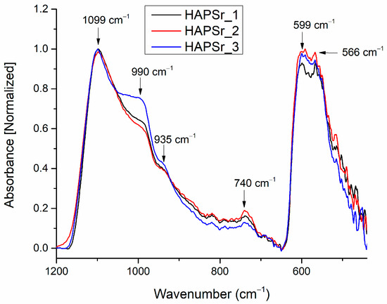
Figure 7.
FTIR spectra of the CaPSr coatings deposited on Si substrates at different substrate temperatures (CaPSr_1, CaPSr_2, and CaPSr_3).
In the wavenumber range 1200–800 cm−1 (see Figure 7), IR bands were identified at the following wavenumbers: 1099 and 990 cm−1, characteristic of the asymmetric stretching of the phosphate ion (ν3 PO43−) [27,28,35]; 935 cm−1, characteristic for the symmetric stretching (ν1) of PO43− [22]; and 740 cm−1, characteristic of P2O74−, possible formed during the plasma deposition [1]. Paper [28] reports findings of the symmetric stretching of PO43− ions at 941 cm−1. In our previous paper [37], which reported the generation of CaPCS layers with magnetron sputtering technique from a CaPCS target, the (ν1) vibrational mode of the phosphate ion was identified at 940 cm−1. Therefore, we suppose that the doping of CaP with Sr or the deposition conditions of the layers leads to shifts in the wavenumber of the IR bands specific to CaPSr samples.
In the wavenumber range 650–400 cm−1 (see Figure 1), two absorption bands, characteristic of the bending mode of PO43− ions in apatite structure, were identified: at 599 cm−1 and 566 cm−1 [21,35,38,39]. There are no absorption bands at 630 cm−1, characteristic of OH groups in HAp structures.
The results presented above indicate that the high temperature from the substrate was conducive to the absence of the OH groups in the CaPSr films. These insights, together with the measured ratio of the (Ca + Sr)/P of ~2, indicate the synthesis of CaPSr layers as Sr-doped TTCP.
The addition of chitosan to the CaPSr samples leads to the modification of the wavenumber positions of the P-O vibrations in PO43− groups. Figure 8 presents the FTIR spectra of the CaPSr_CS samples.
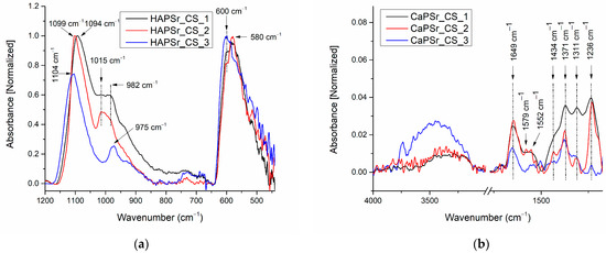
Figure 8.
FTIR spectra of the CaPSr_CS composite coatings deposited on Si substrates at different substrate temperatures (CaPSr_CS_1, CaPSr_CS_2, and CaPSr_CS_3) in the wavenumber range 1200–450 cm−1 (a) and 4000–1200 cm−1 (b).
In the wavenumber range 1200–800 cm−1, it can be observed that, as the substrate was oven heated from room temperature to 400 °C, the 1094 cm−1 IR band (CaPSr_CS_1 sample) was shifted to higher wavenumbers up to 1104 cm−1. For the CaPSr_CS_2 sample, this absorption band is at the same wavenumber as in the case of the CaPSr_2 sample (1099 cm−1). On the contrary, the IR bands observed in the IR spectra of the CaPSr samples at ~990 cm−1, shift to lower wavenumber values: 982 cm−1. A peak at 1015 cm−1, characteristic of the saccharide structure of chitosan [40], was identified for the CaPSr_CS_1 and CaPSr_CS_2 samples (see Figure 8).
In the wavenumber range 650–400 cm−1, the absorption bands specific to the ν4 vibrational mode of PO43− ions are slightly different than those presented in Figure 7. In the case of the CaPSr_CS_1 and CaPSr_CS_2 samples, an absorption band centered at 580 cm−1 is observed, while for the CaPSr_CS_3 sample the absorption band appears at 600 cm−1.
We suppose that the decrease in the intensity of the 1200–900 cm−1 IR band can be attributed to the reduced number of P-O vibrations in the ν3 mode, due to chitosan addition (see Figure 2 and Figure 4). Additionally, the position modifications of the IR band, characteristic of the bending modes of PO43− ions in apatite structures, suggest that the physicochemical processes are encountered between the CaPSr layer and the chitosan.
In Figure 8b and Table 3 are presented the IR bands characteristic of chitosan identified in the 4000–1200 cm−1 spectral range.

Table 3.
The assignment of FTIR absorption bands for the CaPSr_CS coatings in the wavenumber domains: 4000–1200 cm−1.
3.3.1. Peak Fitting Analysis of FTIR Spectra of CaPSr Coatings s
A peak fitting analysis was conducted for revealing the molecular structure of CaPSr and the embedding of chitosan into the CaPSr layers. In addiiton, the influence of the substrate temperature on the layers molecular structure was analyzed.
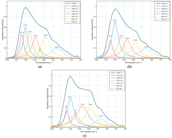
Figure 9.
Deconvoluted FTIR spectra of the CaPSr coatings deposited at different substrate temperatures: CaPSr_1 (a), CaPSr_2 (b), and CaPSr_3 (c) in the 1200–800 cm−1 wavenumber range.
The CaPSr_1, CaPSr_2, and CaPSr_3 samples have similar peak area percentages (Figure 9) for the absorption bands identified at 1120, 1124, and 1119 cm−1, respectively. Previously, Gadaleta et al. assigned the bands at 1127 cm−1 to non-stoichiometric apatite [22,47].
The absorption band at 1022 cm−1 (see Figure 9a) was no longer observed when the substrate was oven heated during the deposition process (see Figure 9b,c). As the substrate temperature was oven increased up to 400 °C, this absorption band seems to have shifted to ~1030 cm−1 (see Figure 9b), while the peak area percentage increased from 18 to 27% (Figure 9b,c). The 1030 cm−1 IR band was formerly attributed to the formation of the CaPSr structure [28,39]. These results suggest that, as the temperature of the substrate is oven increased, Sr-doped apatite structure formation is promoted.
The absorption bands at ~990 cm−1 and ~935 cm−1 had no major shifts in the analyzed samples, with peak area percentages ranging between 15–22% and 11–16%, respectively.

Table 4.
The assignment of FTIR absorption bands for the CaPSr and CaPSr_CS coatings in the wavenumber domain 1200–800 cm−1.
Table 4.
The assignment of FTIR absorption bands for the CaPSr and CaPSr_CS coatings in the wavenumber domain 1200–800 cm−1.
| Wavenumber (cm−1) | FTIR Band Assignment | Ref. | |||||
|---|---|---|---|---|---|---|---|
| CaPSr_1 | CaPSr_2 | CaPSr_3 | CaPSr_CS_1 | CaPSr_CS_2 | CaPSr_CS_3 | ||
| 1134 | Asymmetric stretching of C-O-C | [41,48] | |||||
| 1120 | 1124 | 1119 | 1111 | 1108 | 1119 | P-O vibration in non-apatite phosphate structure | [47] |
| 1099,1075, 1045, 1022 | 1099,1068, 1033 | 1099, 1075,1034 | 1094,1073, 1047 | 1099, 1080,1055, | 1104, 1082, 1055 | ν3 PO43− | [21,35,38,39,49,50,51] |
| 990 | 989 | 990 | 982 | 982 | 976 | ν3 PO43− in TTCP | [27,28] |
| 52 | 1015 | 1015 | polysaccharide structure of CS | [40] | |||
| 930 | 935 | 935 | 934 | 929 | 929 | ν1 PO43− | [22,37] |
3.3.2. Peak Fitting Analysis of FTIR Spectra of CaPSr_CS Coatings
The peak fitting analysis of the CaPSr_CS samples FTIR spectra are presented in Figure 10 and Table 4. Slight modifications of the deconvoluted IR band positions, as functions of the oven-controlled temperature at the substrate during the deposition process of the CaPSr layers, can be observed. The addition of chitosan on their surface is conducive to these modifications due to some physicochemical interactions. In Figure 10a,b the deconvoluted IR band from 1015 cm−1, specific to chitosan structure, is evidenced. Although this band did not appear in the deconvoluted spectrum of the CaPSr_CS_3 sample, a new deconvolution band was observed at 1134 cm−1 which that could be attributed to the asymmetric stretching of C-O-C bonds of the chitosan structure [41,48].
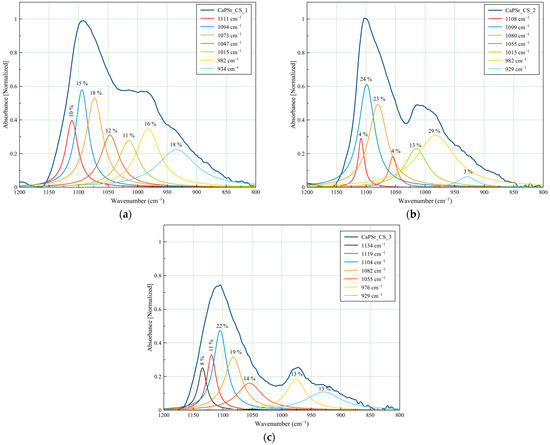
Figure 10.
Deconvoluted FTIR spectra of the CaPSr coatings deposited at different substrate temperatures: CaPSr_CS_1 (a), CaPSr_CS_2 (b), and CaPSr_CS_3 (c) in the 1200–800 cm−1 wavenumber range.
3.4. QMS Monitoring of the Species Released from the CaPSr_CS Coatings during LIA Process
The ion currents of the species released during the laser–sample interaction from the CaPSr_CS layers deposited on Si substrates are presented in Figure 11.
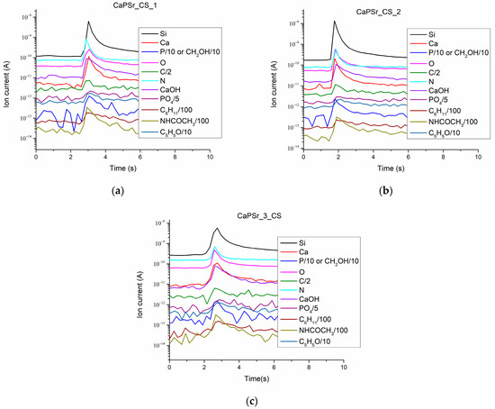
Figure 11.
Ion current as a function of time for the species released from the CaPSr_CS coatings during LIA at nominal laser pulse energy: CaPSr_1_CS (a), CaPSr_2_CS (b), and CaPSr_3_CS (c).
The collected Ca+ (m/q = 40), CaOH+ (m/q = 57), P+ (m/q = 31), and PO4+ (m/q = 95) ion currents are characteristic of the apatite structure of the layers. These positive molecular ions specific to calcium phosphate were previous identified by time-of-flight secondary ion mass spectrometry [52,53,54,55,56,57].
The presence of chitosan in the CaPSr_CS coatings is highlighted mainly by the detection of the following molecular ions: C6H11+ (m/q = 83), NHCOCH3+ (m/q = 58), C5H5O (m/q = 81). The detection of NHCOCH3+ (m/q = 58) is due to the N-acetyl glucosamine unit of the chitosan structure.
The C+, N+, O+ ions were also identified. The signal of the Si+ ion current confirms that, during the laser ablation of the layers, the substrate is attained. This means that chitosan is embedded in the CaPSr layers, except, perhaps the microparticles formed on their surfaces. Moreover, the simultaneous detection of ions characteristic both of CaPs and chitosan and the SEM analysis of the layer morphologies sustain the above ascertainment.
4. Conclusions
Strontium-doped calcium phosphate/chitosan composite layers were synthetized using plasma and laser techniques, namely radio-frequency magnetron sputtering and matrix-assisted pulsed laser evaporation.
The formation of strontium-doped tetra calcium phosphate layers was possible by tuning the temperature of the substrate during the magnetron sputtering deposition processes. The morphology of the layer surfaces evolves from grain structures to microchannels structures, with increases in the temperature of the substrate.
The FTIR and EDX spectral analysis indicated the absence of OH groups from apatite structure (no molecular bands at 3570 and 630 cm−1) and the (Ca+Sr)/P atomic ratio of ~2, that are characteristic of tetra calcium phosphate compounds. The further deposition of chitosan on strontium-doped calcium phosphate layers does not change these data.
The presence of chitosan in the layers was highlighted by SEM, FTIR spectroscopy, and LIA—QMS analysis. All the IR bands characteristic of chitosan were revealed. The collected mass spectra showed C6H11+ (m/q = 83), NHCOCH3+ (m/q = 58), and C5H5O+ (m/q = 81) ions, specific to the chitosan chemical structure.
Author Contributions
Conceptualization, A.G., B.B. and I.N.; investigation, A.G., M.E.Z., S.A.Y.-A., B.B. and I.N.; resources, A.G., B.B. and I.N.; validation, A.G., M.E.Z., S.A.Y.-A., B.B. and I.N.; writing—original draft preparation, A.G. and M.E.Z.; writing—review and editing, A.G., M.E.Z., S.A.Y.-A., B.B. and I.N.; visualization, A.G. and M.E.Z.; supervision, A.G. All authors have read and agreed to the published version of the manuscript.
Funding
This research was supported by Romanian Ministry of Research, Innovation and Digitalization under Romanian National Core Program LAPLAS VII—contract no. 30N/2023.
Institutional Review Board Statement
Not applicable.
Data Availability Statement
The data presented in this study are available on request from the corresponding author.
Acknowledgments
This research was supported (or financed) by the Romanian Ministry of Research, Innovation and Digitalization under Romanian National Core Program LAPLAS VII—contract no. 30N/2023. I.N. acknowledges the support of a grant from the Ministry of Research, Innovation and Digitization, CNCS—UEFISCDI, project number PN-III-P1-1.1-PD-2021-0598 within PNCDI III. M.E.Z. expresses thanks to Eng. Ecaterina Andronescu for the guidance and for the fruitful discussions regarding the research subject of dopped calcium phosphates. M.E.Z. gives thanks to Alexandra Catalina Birca and Cristina Chircov for the help provided during the Microwave-assisted Hydrothermal synthesis.
Conflicts of Interest
The authors declare no conflict of interest. The funders had no role in the design of the study; in the collection, analyses, or interpretation of data; in the writing of the manuscript, or in the decision to publish the results.
References
- Berzina-Cimdina, L.; Borodajenko, N. Research of calcium phosphates using fourier transform infrared spectroscopy. In Infrared Spectroscopy—Materials Science, Engineering and Technology; InTech: Houston, TX, USA, 2012. [Google Scholar]
- Antoniac, I.V. Handbook of Bioceramics and Biocomposites; Springer: Berlin/Heidelberg, Germany, 2016; ISBN 9783319124605. [Google Scholar]
- Mohd Pu’ad, N.A.S.; Haq, R.H.A.; Mohd Noh, H.; Abdullah, H.Z.; Idris, M.I.; Lee, T.C. Selection and Peer-Review under Responsibility of 4th Advanced Materials Conference; Elsevier: Amsterdam, The Netherlands, 2018. [Google Scholar] [CrossRef]
- Balhuc, S.; Campian, R.; Labunet, A.; Negucioiu, M.; Buduru, S.; Kui, A. Dental Applications of Systems Based on Hydroxyapatite Nanoparticles—An Evidence-Based Update. Crystals 2021, 11, 674. [Google Scholar] [CrossRef]
- Schmidt, R.; Gonjal, J.P.; Morán, E. Microwaves: Microwave-Assisted Hydrothermal Synthesis of Nanoparticles. In CRC Concise Encyclopedia of Nanotechnology; CRC Press: Boca Raton, FL, USA, 2016; pp. 588–599. ISBN 9781466580343. [Google Scholar]
- Yang, G.; Park, S.J. Conventional and Microwave Hydrothermal Synthesis and Application of Functional Materials: A Review. Materials 2019, 12, 1177. [Google Scholar] [CrossRef] [PubMed]
- Solomon, G.; Mazzaro, R.; Morandi, V.; Concina, I.; Vomiero, A. Microwave-Assisted vs. Conventional Hydrothermal Synthesis of MoS2 Nanosheets: Application towards Hydrogen Evolution Reaction. Crystals 2020, 10, 1040. [Google Scholar] [CrossRef]
- Lu, M.; Chen, H.; Yuan, B.; Zhou, Y.; Min, L.; Xiao, Z.; Zhu, X.; Tu, C.; Zhang, X. Electrochemical Deposition of Nanostructured Hydroxyapatite Coating on Titanium with Enhanced Early Stage Osteogenic Activity and Osseointegration. Int. J. Nanomed. 2020, 15, 6605–6618. [Google Scholar] [CrossRef]
- Popa, M.V.; Moreno, J.M.C.; Popa, M.; Vasilescu, E.; Drob, P.; Vasilescu, C.; Drob, S.I. Electrochemical Deposition of Bioactive Coatings on Ti and Ti–6Al–4V Surfaces. Surf. Coatings Technol. 2011, 205, 4776–4783. [Google Scholar] [CrossRef]
- Stoch, A.; Brożek, A.; Kmita, G.; Stoch, J.; Jastrzębski, W.; Rakowska, A. Electrophoretic Coating of Hydroxyapatite on Titanium Implants. J. Mol. Struct. 2001, 596, 191–200. [Google Scholar] [CrossRef]
- Beig, B.; Liaqat, U.; Niazi, M.F.K.; Douna, I.; Zahoor, M.; Niazi, M.B.K. Current Challenges and Innovative Developments in Hydroxyapatite-Based Coatings on Metallic Materials for Bone Implantation: A Review. Coatings 2020, 10, 1249. [Google Scholar] [CrossRef]
- Bigi, A.; Boanini, E.; Bracci, B.; Facchini, A.; Panzavolta, S.; Segatti, F.; Sturba, L. Nanocrystalline Hydroxyapatite Coatings on Titanium: A New Fast Biomimetic Method. Biomaterials 2005, 26, 4085–4089. [Google Scholar] [CrossRef]
- Kowalski, S.; Gonciarz, W.; Belka, R.; Góral, A.; Chmiela, M.; Lechowicz, Ł.; Kaca, W.; Żórawski, W. Plasma-Sprayed Hydroxyapatite Coatings and Their Biological Properties. Coatings 2022, 12, 1317. [Google Scholar] [CrossRef]
- Jeong, Y.H.; Choe, H.C.; Eun, S.W. Hydroxyapatite Coating on the Ti-35Nb-XZr Alloy by Electron Beam-Physical Vapor Deposition. Thin Solid Film. 2011, 519, 7050–7056. [Google Scholar] [CrossRef]
- Man, H.C.; Chiu, K.Y.; Cheng, F.T.; Wong, K.H. Adhesion Study of Pulsed Laser Deposited Hydroxyapatite Coating on Laser Surface Nitrided Titanium. Thin Solid Film. 2009, 517, 5496–5501. [Google Scholar] [CrossRef]
- Nelea, V.; Morosanu, C.; Iliescu, M.; Mihailescu, I.N. Hydroxyapatite Thin Films Grown by Pulsed Laser Deposition and Radio-Frequency Magnetron Sputtering: Comparative Study. Appl. Surf. Sci. 2004, 228, 346–356. [Google Scholar] [CrossRef]
- Filip, D.G.; Surdu, V.-A.; Paduraru, A.V.; Andronescu, E. Current Development in Biomaterials—Hydroxyapatite and Bioglass for Applications in Biomedical Field: A Review. J. Funct. Biomater. 2022, 13, 248. [Google Scholar] [CrossRef] [PubMed]
- Ressler, A.; Žužić, A.; Ivanišević, I.; Kamboj, N.; Ivanković, H. Ionic Substituted Hydroxyapatite for Bone Regeneration Applications: A Review. Open Ceram. 2021, 6, 100122. [Google Scholar] [CrossRef]
- Mondal, S.; Dorozhkin, S.V.; Pal, U. Recent Progress on Fabrication and Drug Delivery Applications of Nanostructured Hydroxyapatite. WIREs Nanomed. Nanobiotechnol. 2018, 10, e1504. [Google Scholar] [CrossRef]
- Rivera-Muñoz, E.M. Hydroxyapatite-Based Materials: Synthesis and Characterization. In Biomedical Engineering—Frontiers and Challenges; InTech: Houston, TX, USA, 2011; ISBN 978-953-307-309-5. [Google Scholar]
- Baldassarre, F.; Altomare, A.; Mesto, E.; Lacalamita, M.; Dida, B.; Mele, A.; Bauer, E.M.; Puzone, M.; Tempesta, E.; Capelli, D.; et al. Structural Characterization of Low-Sr-Doped Hydroxyapatite Obtained by Solid-State Synthesis. Crystals 2023, 13, 117. [Google Scholar] [CrossRef]
- Zarif, M.E.; Yehia-Alexe, S.A.; Bita, B.; Negut, I.; Locovei, C.; Groza, A. Calcium Phosphates–Chitosan Composite Layers Obtained by Combining Radio-Frequency Magnetron Sputtering and Matrix-Assisted Pulsed Laser Evaporation Techniques. Polymers 2022, 14, 5241. [Google Scholar] [CrossRef]
- Kelly, P.; Arnell, R. Magnetron Sputtering: A Review of Recent Developments and Applications. Vacuum 2000, 56, 159–172. [Google Scholar] [CrossRef]
- Surmenev, R.A.; Surmeneva, M.A.; Grubova, I.Y.; Chernozem, R.V.; Krause, B.; Baumbach, T.; Loza, K.; Epple, M. RF Magnetron Sputtering of a Hydroxyapatite Target: A Comparison Study on Polytetrafluorethylene and Titanium Substrates. Appl. Surf. Sci. 2017, 414, 335–344. [Google Scholar] [CrossRef]
- Yang, S.; Zhang, J. Matrix-Assisted Pulsed Laser Evaporation (MAPLE) Technique for Deposition of Hybrid Nanostructures. Front. Nanosci. Nanotechnol. 2017, 3. [Google Scholar] [CrossRef]
- Hou, X.; Zhang, L.; Zhou, Z.; Luo, X.; Wang, T.; Zhao, X.; Lu, B.; Chen, F.; Zheng, L. Calcium Phosphate-Based Biomaterials for Bone Repair. J. Funct. Biomater. 2022, 13, 187. [Google Scholar] [CrossRef]
- Lukosevicius, L. Advances and Challenges in Sputter Deposition of Biomaterial Coatings from a Loosely Packed Hydroxyapatite Powder Target. Ph.D. Thesis, The University of Manchester, Manchester, UK, 2020. [Google Scholar]
- Moseke, C.; Gbureck, U. Tetracalcium Phosphate: Synthesis, Properties and Biomedical Applications. Acta Biomater. 2010, 6, 3815–3823. [Google Scholar] [CrossRef] [PubMed]
- Sparkman, O.D. Book & Media Reviews Mass Spectrometry Desk Reference. J. Chem. Educ. 2001, 78, 168. [Google Scholar]
- Shapovalov, V.I.; Komlev, A.E.; Bondarenko, A.S.; Baykov, P.B.; Karzin, V.V. Substrate Heating and Cooling during Magnetron Sputtering of Copper Target. Phys. Lett. A 2016, 380, 882–885. [Google Scholar] [CrossRef]
- Groza, A.; Surmeian, A. Characterization of the Oxides Present in a Polydimethylsiloxane Layer Obtained by Polymerisation of Its Liquid Precursor in Corona Discharge. J. Nanomater. 2015, 2015, 204296. [Google Scholar] [CrossRef]
- Yehia-Alexe, S.-A.; Groza, A.; Serbanescu, M.; Zarif, M.E.; Bita, B.; Dinca, P.; Butoi, B.; Staicu, C.; Porosnicu, C. Considerations on Hydrogen Isotopes Release from Thin Films by Laser Induced Ablation and Laser Induced Desorption Techniques. Spectrochim. Acta Part B At. Spectrosc. 2023, 208, 106774. [Google Scholar] [CrossRef]
- Bramowicz, M.; Braic, L.; Azem, F.A.; Kulesza, S.; Birlik, I.; Vladescu, A. Mechanical Properties and Fractal Analysis of the Surface Texture of Sputtered Hydroxyapatite Coatings. Appl. Surf. Sci. 2016, 379, 338–346. [Google Scholar] [CrossRef]
- Visan, A.; Stan, G.E.; Ristoscu, C.; Popescu-Pelin, G.; Sopronyi, M.; Besleaga, C.; Luculescu, C.; Chifiriuc, M.C.; Hussien, M.D.; Marsan, O.; et al. Combinatorial MAPLE Deposition of Antimicrobial Orthopedic Maps Fabricated from Chitosan and Biomimetic Apatite Powders. Int. J. Pharm. 2016, 511, 505–515. [Google Scholar] [CrossRef]
- Xu, Y.; An, L.; Chen, L.; Xu, H.; Zeng, D.; Wang, G. Controlled Hydrothermal Synthesis of Strontium-Substituted Hydroxyapatite Nanorods and Their Application as a Drug Carrier for Proteins. Adv. Powder Technol. 2018, 29, 1042–1048. [Google Scholar] [CrossRef]
- Bala, Y.; Farlay, D.; Delmas, P.D.; Meunier, P.J.; Boivin, G. Time Sequence of Secondary Mineralization and Microhardness in Cortical and Cancellous Bone from Ewes. Bone 2010, 46, 1204–1212. [Google Scholar] [CrossRef]
- Dreghici, D.B.; Butoi, B.; Predoi, D.; Iconaru, S.L.; Stoican, O.; Groza, A. Chitosan–Hydroxyapatite Composite Layers Generated in Radio Frequency Magnetron Sputtering Discharge: From Plasma to Structural and Morphological Analysis of Layers. Polymers 2020, 12, 3065. [Google Scholar] [CrossRef] [PubMed]
- Tsai, S.-W.; Yu, W.-X.; Hwang, P.-A.; Huang, S.-S.; Lin, H.-M.; Hsu, Y.-W.; Hsu, F.-Y. Fabrication and Characterization of Strontium-Substituted Hydroxyapatite-CaO-CaCO3 Nanofibers with a Mesoporous Structure as Drug Delivery Carriers. Pharmaceutics 2018, 10, 179. [Google Scholar] [CrossRef] [PubMed]
- Frangopol, P.T.; Mocanu, A.; Almasan, V.; Garbo, C.; Balint, R.; Borodi, G.; Bratu, I.; Horovitz, O.; Tomoaia-Cotisel, M. Synthesis and Structural Characterization of Strontium Substituted Hydroxyapatites. Rev. Roum. Chim. 2016, 61, 337–344. [Google Scholar]
- Zolghadri, M.; Saber-Samandari, S.; Ahmadi, S.; Alamara, K. Synthesis and Characterization of Porous Cytocompatible Scaffolds from Polyvinyl Alcohol-Chitosan. Bull. Mater. Sci. 2019, 42, 35. [Google Scholar] [CrossRef]
- Coates, J. Interpretation of infrared spectra, a practical approach. In Encyclopedia of Analytical Chemistry; Wiley: Chichester, UK, 2000. [Google Scholar]
- Fernandes Queiroz, M.; Melo, K.; Sabry, D.; Sassaki, G.; Rocha, H. Does the Use of Chitosan Contribute to Oxalate Kidney Stone Formation? Mar. Drugs 2014, 13, 141–158. [Google Scholar] [CrossRef] [PubMed]
- El-araby, A.; El Ghadraoui, L.; Errachidi, F. Usage of Biological Chitosan against the Contamination of Post-Harvest Treatment of Strawberries by Aspergillus Niger. Front. Sustain. Food Syst. 2022, 6, 141–158. [Google Scholar] [CrossRef]
- Xianmiao, C.; Yubao, L.; Yi, Z.; Li, Z.; Jidong, L.; Huanan, W. Properties and in Vitro Biological Evaluation of Nano-Hydroxyapatite/Chitosan Membranes for Bone Guided Regeneration. Mater. Sci. Eng. C 2009, 29, 29–35. [Google Scholar] [CrossRef]
- Butler, D.H.; Shahack-Gross, R. Formation of Biphasic Hydroxylapatite-Beta Magnesium Tricalcium Phosphate in Heat Treated Salmonid Vertebrae. Sci. Rep. 2017, 7, 3610. [Google Scholar] [CrossRef]
- Lv, S.H. High-Performance Superplasticizer Based on Chitosan. In Biopolymers and Biotech Admixtures for Eco-Efficient Construction Materials; Elsevier: Amsterdam, The Netherlands, 2016; pp. 131–150. ISBN 9780081002148. [Google Scholar]
- Gadaleta, S.J.; Paschalis, E.P.; Betts, F.; Mendelsohn, R.; Boskey, A.L. Fourier Transform Infrared Spectroscopy of the Solution-Mediated Conversion of Amorphous Calcium Phosphate to Hydroxyapatite: New Correlations between X-Ray Diffraction and Infrared Data. Calcif. Tissue Int. 1996, 58, 9–16. [Google Scholar] [CrossRef]
- Zhang, Y.-P.; Wang, X.; Shen, Y.; Thakur, K.; Zhang, J.-G.; Hu, F.; Wei, Z.-J. Preparation and Characterization of Bio-Nanocomposites Film of Chitosan and Montmorillonite Incorporated with Ginger Essential Oil and Its Application in Chilled Beef Preservation. Antibiotics 2021, 10, 796. [Google Scholar] [CrossRef]
- Delgado-López, J.M.; Iafisco, M.; Rodríguez, I.; Tampieri, A.; Prat, M.; Gómez-Morales, J. Crystallization of Bioinspired Citrate-Functionalized Nanoapatite with Tailored Carbonate Content. Acta Biomater. 2012, 8, 3491–3499. [Google Scholar] [CrossRef] [PubMed]
- Boyd, A.R.; Rutledge, L.; Randolph, L.D.; Mutreja, I.; Meenan, B.J. The Deposition of Strontium-Substituted Hydroxyapatite Coatings. J. Mater. Sci. Mater. Med. 2015, 26, 65. [Google Scholar] [CrossRef]
- Lin, K.; Liu, P.; Wei, L.; Zou, Z.; Zhang, W.; Qian, Y.; Shen, Y.; Chang, J. Strontium Substituted Hydroxyapatite Porous Microspheres: Surfactant-Free Hydrothermal Synthesis, Enhanced Biological Response and Sustained Drug Release. Chem. Eng. J. 2013, 222, 49–59. [Google Scholar] [CrossRef]
- Ghumman, C.A.A.; Carreira, O.M.T.; Moutinho, A.M.C.; Tolstogouzov, A.; Vassilenko, V.; Teodoro, O.M.N.D. Identification of Human Calculi with Time-of-Flight Secondary Ion Mass Spectrometry. Rapid Commun. Mass Spectrom. 2010, 24, 185–190. [Google Scholar] [CrossRef]
- Ghumman, C.A.A.; Moutinho, A.M.C.; Tolstogouzov, A.; Teodoro, O.M.N.D. Time-of-Flight Secondary Ion Mass Spectrometric Identification of Calcium Formate Ca(HCO2)2 and Metabolite of Vitamin B6 in Human Stones. Rapid Commun. Mass Spectrom. 2011, 25, 997–999. [Google Scholar] [CrossRef] [PubMed]
- Ghumman, C.A.A.; Moutinho, A.M.C.; Santos, A.; Tolstogouzov, A.; Teodoro, O.M.N.D. TOF-SIMS Study of Cystine and Cholesterol Stones. J. Mass Spectrom. 2012, 47, 547–551. [Google Scholar] [CrossRef]
- Ghumman, C.A.A.; Moutinho, A.M.C.; Santos, A.; Teodoro, O.M.N.D.; Tolstogouzov, A. An Upgraded TOF-SIMS VG Ionex IX23LS: Study on the Negative Secondary Ion Emission of III-V Compound Semiconductors with Prior Neutral Cesium Deposition. Appl. Surf. Sci. 2012, 258, 2490–2497. [Google Scholar] [CrossRef]
- Ghumman, C.A.A.; Moutinho, A.M.C.; Santos, A.; Tolstogouzov, A.; Teodoro, O.M.N.D. TOF-SIMS VG Ionex IX23LS: Upgrade and application for the urinary stones analysis. In Surface and Interface Analysis; John Wiley & Sons, Ltd.: Hoboken, NJ, USA, 2013; Volume 45, pp. 532–536. [Google Scholar]
- Liu, H.; Yoo, H.J.; Håkansson, K. Characterization of Phosphate-Containing Metabolites by Calcium Adduction and Electron Capture Dissociation. J. Am. Soc. Mass Spectrom. 2008, 19, 799–808. [Google Scholar] [CrossRef]
Disclaimer/Publisher’s Note: The statements, opinions and data contained in all publications are solely those of the individual author(s) and contributor(s) and not of MDPI and/or the editor(s). MDPI and/or the editor(s) disclaim responsibility for any injury to people or property resulting from any ideas, methods, instructions or products referred to in the content. |
© 2023 by the authors. Licensee MDPI, Basel, Switzerland. This article is an open access article distributed under the terms and conditions of the Creative Commons Attribution (CC BY) license (https://creativecommons.org/licenses/by/4.0/).


