
Three-Dimensional-Printed Composite Scaffolds Containing Poly-ε-Caprolactone and Strontium-Doped Hydroxyapatite for Osteoporotic Bone Restoration

 , , ,
, , ,  , , and
Abstract
:1. Introduction
2. Materials and Methods
2.1. Synthesis of HA and SrHA Powders
2.2. Design and Manufacturing of 3D Composite Scaffolds
2.3. Characterization Methods of 3D Composite Scaffolds
2.3.1. General Overview of Characterization Methods
2.3.2. Thermogravimetric (TG) Analysis
2.3.3. Scanning Electron Microscopy (SEM) Analysis
2.3.4. Mechanical Properties
2.3.5. In Vitro Chemical Bioactivity
2.3.6. In Vitro Biological Evaluation
2.3.7. Statistical Analysis
3. Results and Discussion
3.1. PCL 70% (wt.)–HA/SrHA 30% (wt.) Scaffolds Design
3.2. Thermogravimetric (TG) Analysis
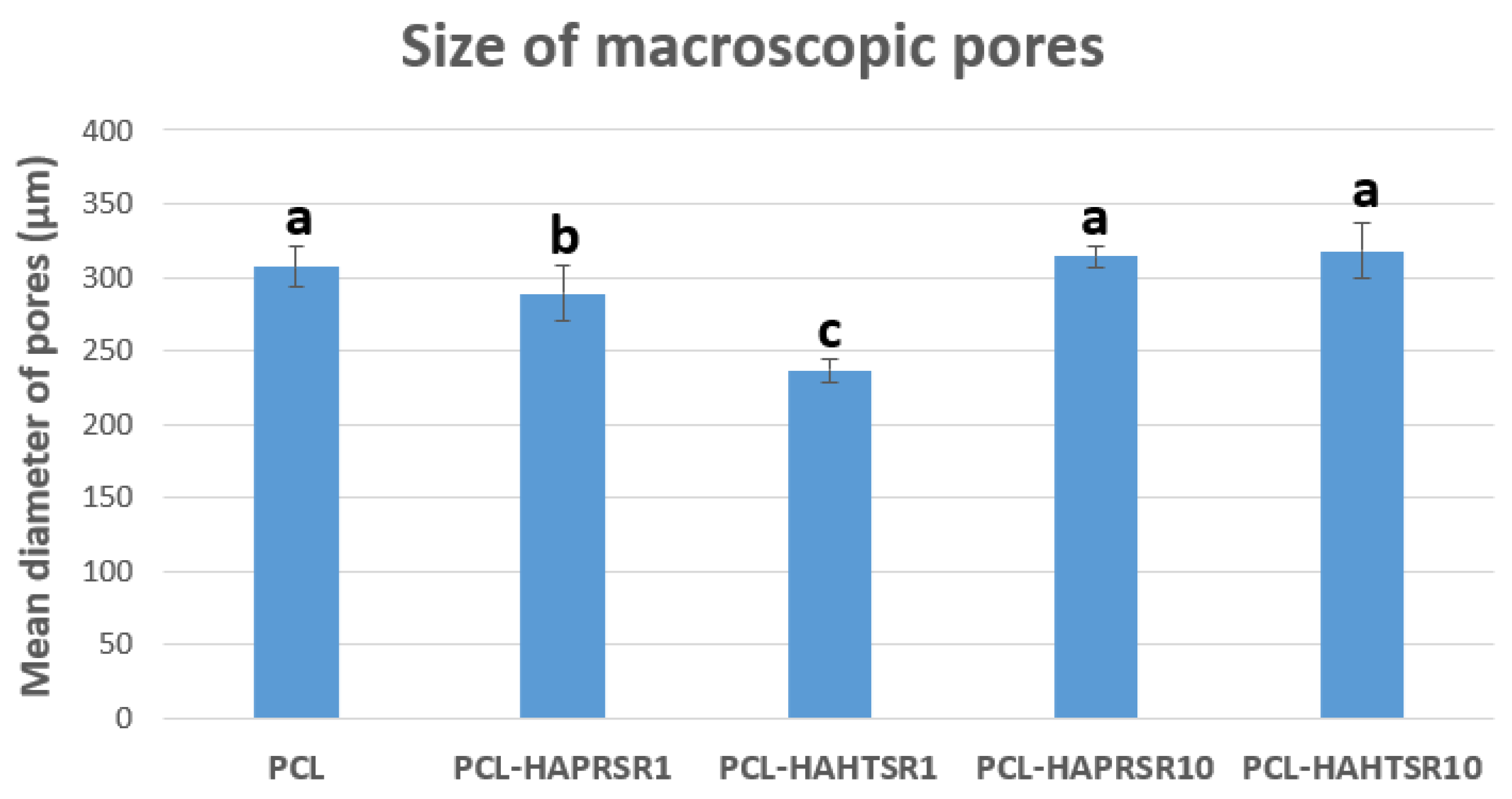
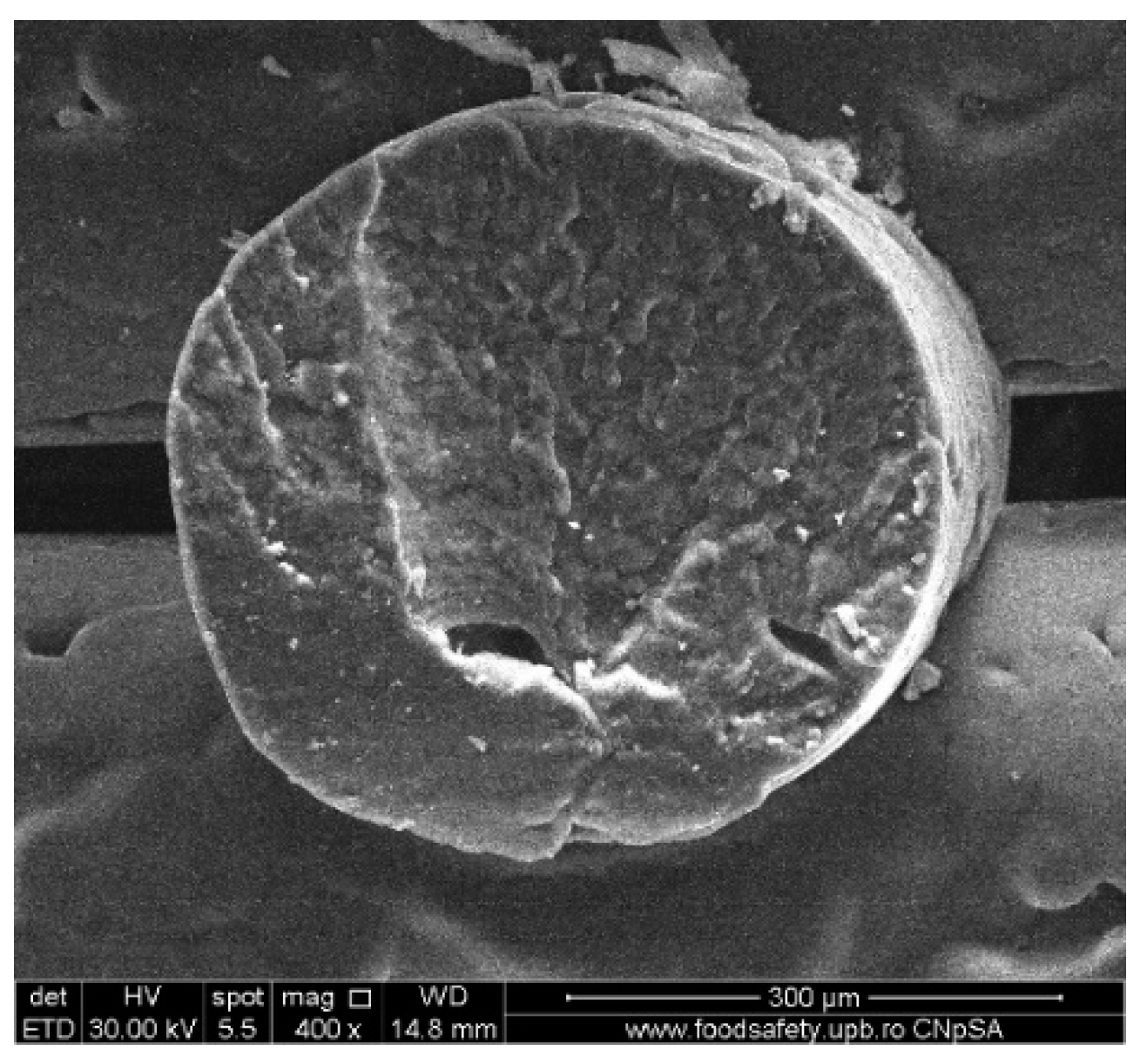
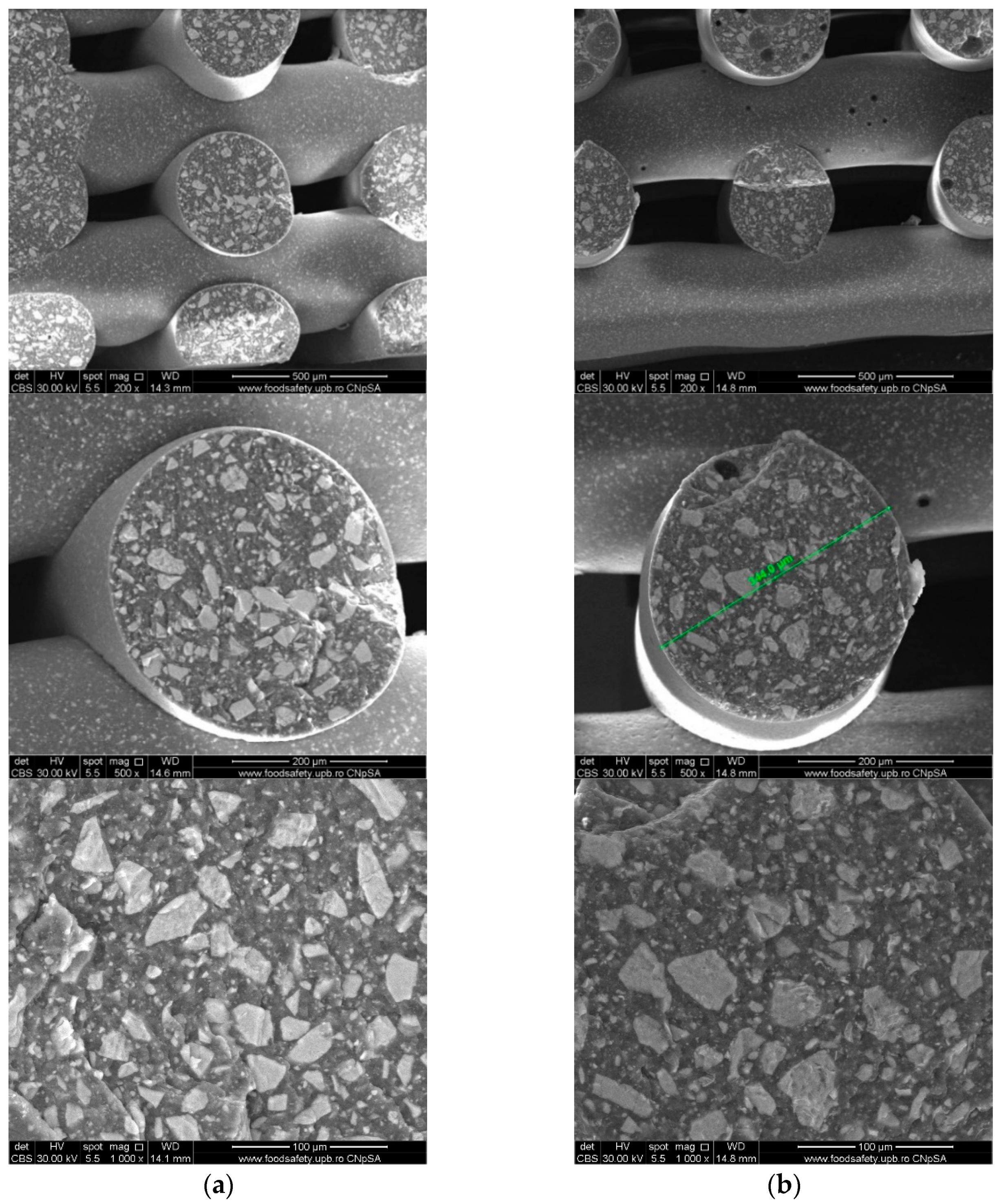
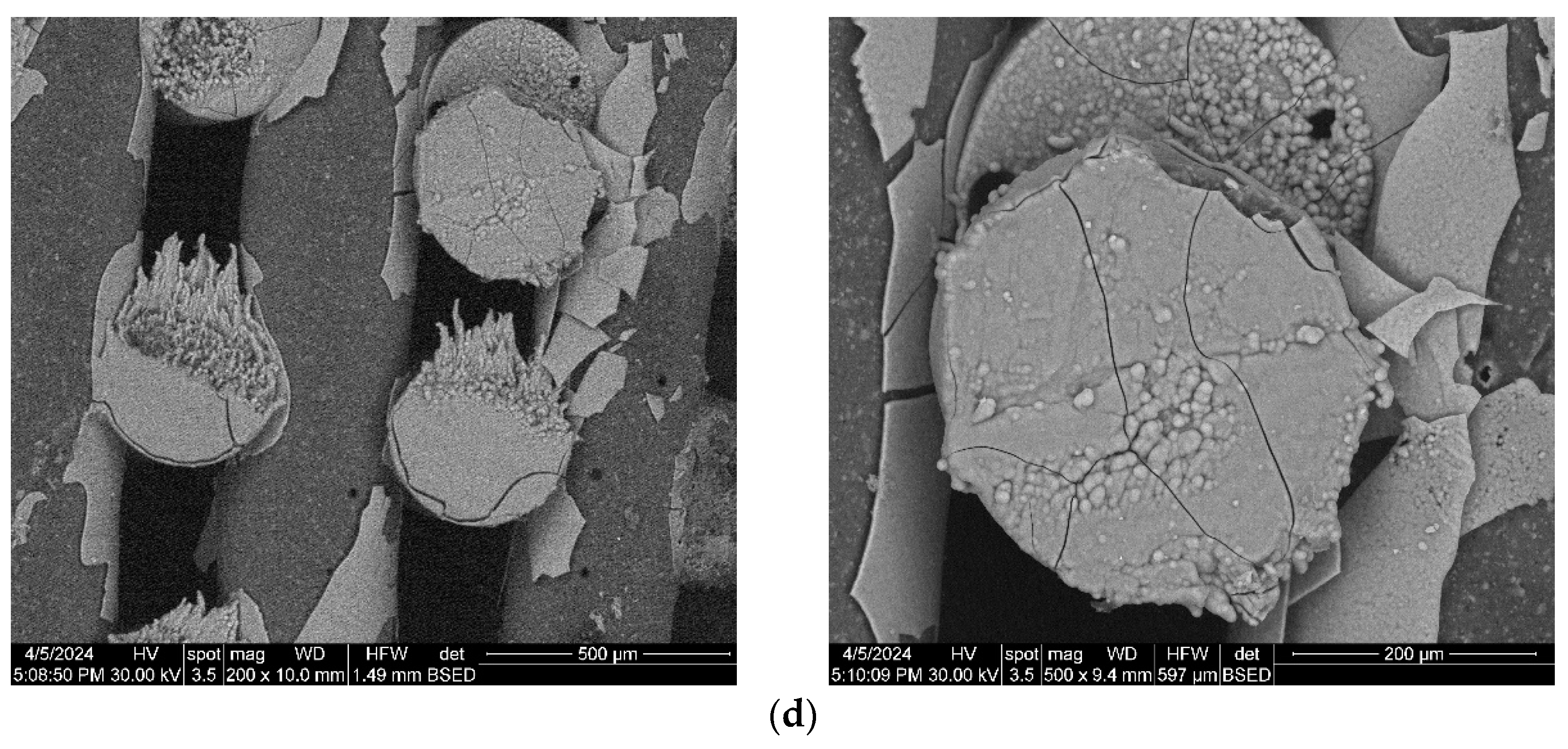
3.3. Scanning Electron Microscopy
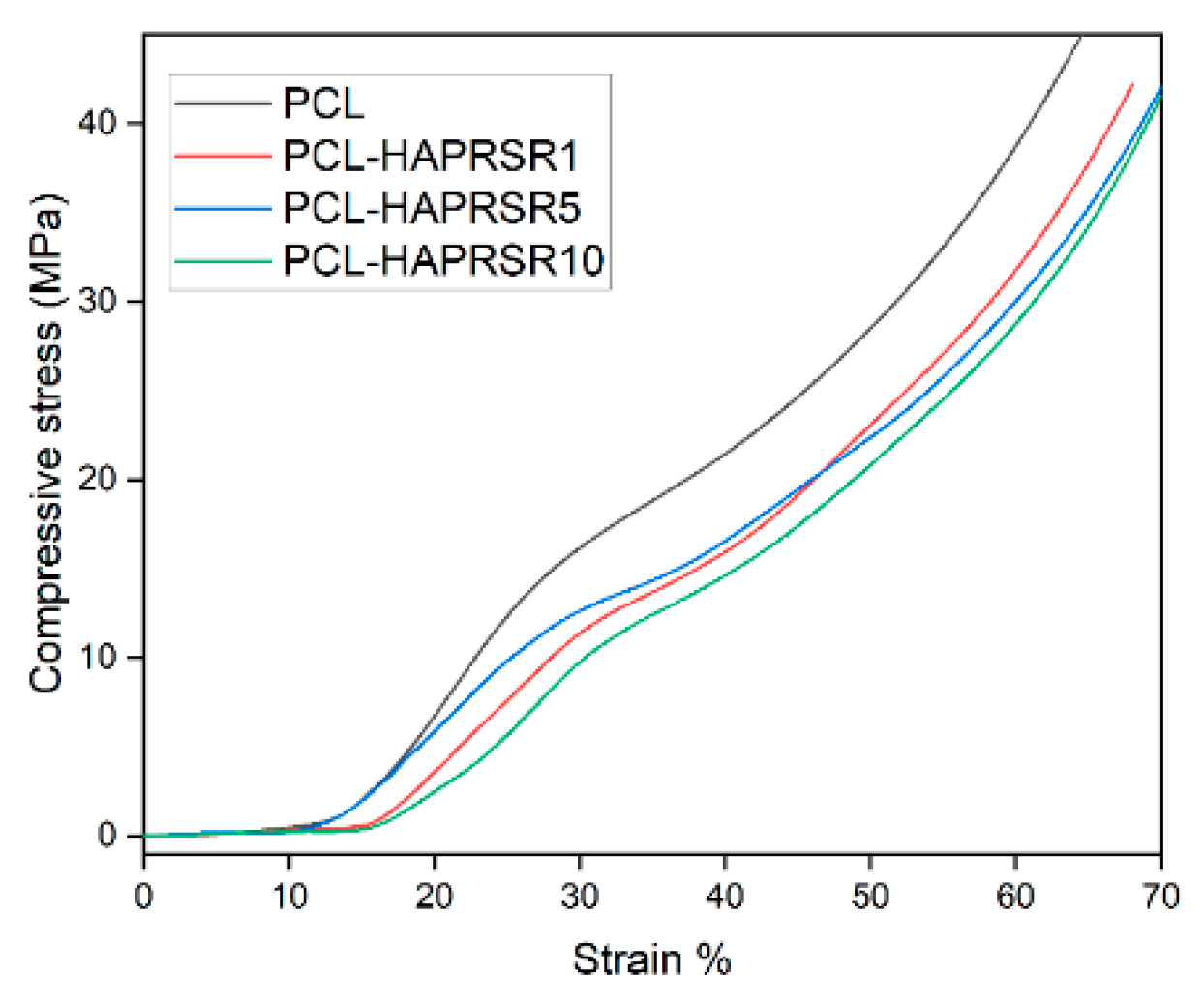
3.4. Mechanical Characterization
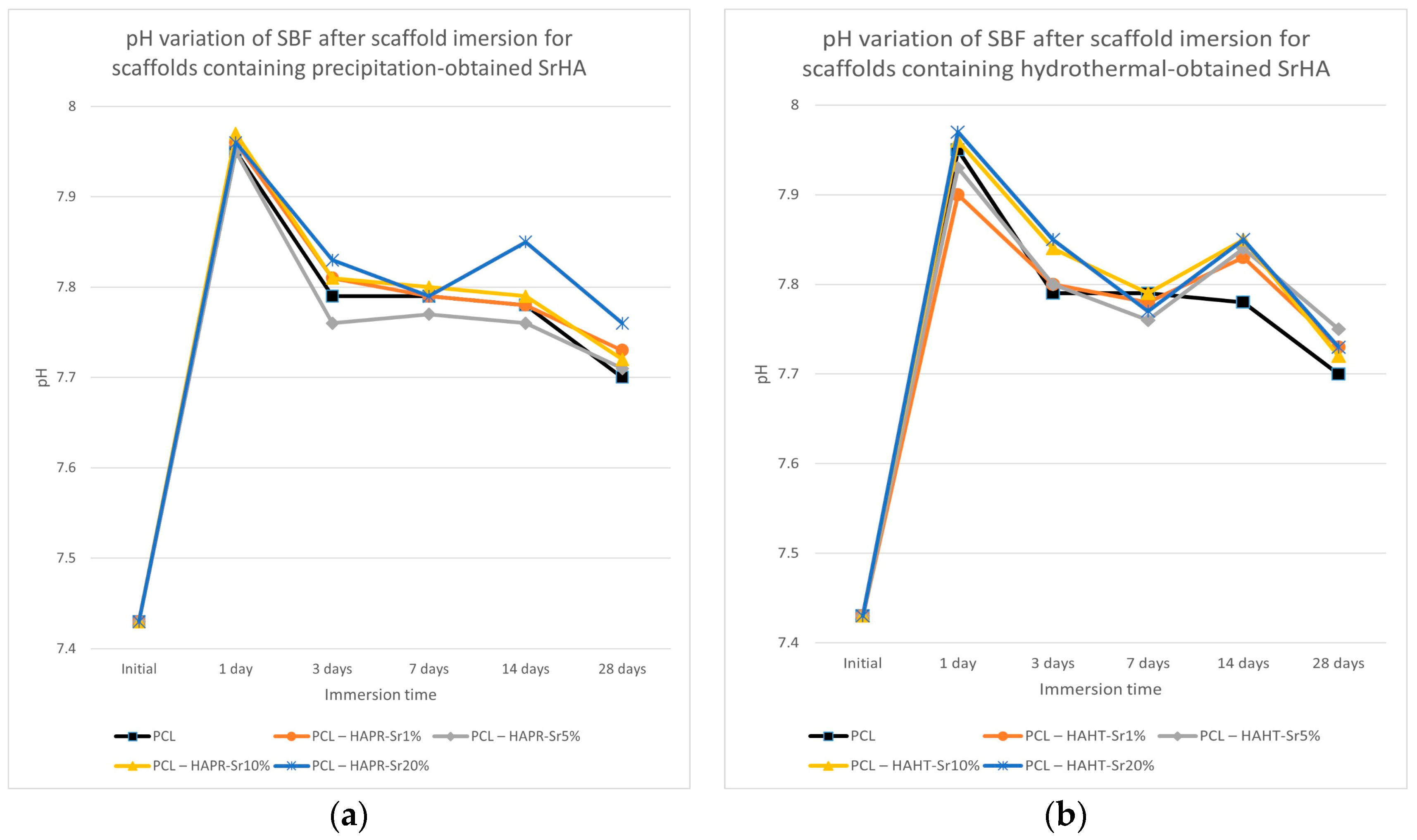
3.5. Chemical In Vitro Bioactivity
3.6. Biological In Vitro Scaffold Performance
4. Conclusions
Supplementary Materials
Author Contributions
Funding
Data Availability Statement
Conflicts of Interest
References
- Dumitrescu, C.R.; Neacsu, I.A.; Surdu, V.A.; Nicoara, A.I.; Codrea, C.I.; Pop, C.E.; Trusca, R.; Andronescu, E. Maturation of Hydroxyapatite from Biogenic Calcium Source—A Comparative Study. U.P.B. Sci. Bull. Ser. B 2022, 84, 21–30. [Google Scholar]
- Ashrafi, M.; Ghalichi, F.; Mirzakouchaki, B.; Doblare, M. On the Effect of Antiresorptive Drugs on the Bone Remodeling of the Mandible after Dental Implantation: A Mathematical Model. Sci. Rep. 2021, 11, 2792. [Google Scholar] [CrossRef]
- Dumitrescu, C.R.; Neacsu, I.A.; Surdu, V.A.; Nicoara, A.I.; Iordache, F.; Trusca, R.; Ciocan, L.T.; Ficai, A.; Andronescu, E. Nano-Hydroxyapatite vs. Xenografts: Synthesis, Characterization, and In Vitro Behavior. Nanomaterials 2021, 11, 2289. [Google Scholar] [CrossRef] [PubMed]
- Custodio, C.L.; Broñola, P.J.M.; Cayabyab, S.R.; Lagura, V.U.; Celorico, J.R.; Basilia, B.A. Powder Loading Effects on the Physicochemical and Mechanical Properties of 3D Printed Poly Lactic Acid/Hydroxyapatite Biocomposites. Int. J. Bioprint 2021, 7, 326. [Google Scholar] [CrossRef] [PubMed]
- Lin, K.; Chang, J. 1—Structure and Properties of Hydroxyapatite for Biomedical Applications. In Hydroxyapatite (Hap) for Biomedical Applications; Mucalo, M., Ed.; Woodhead Publishing: Cambridge, UK, 2015; pp. 3–19. [Google Scholar] [CrossRef]
- Zhu, T.; Li, J.; Cui, L.; Zhang, Z.; Zhuang, X.; Ding, J. Poly(Lactic-Co-Glycolic Acid)-Based Composite Bone-Substitute Materials. Bioact. Mater. 2021, 6, 346–360. [Google Scholar] [CrossRef] [PubMed]
- Jakus, A.E.; Rutz, A.L.; Jordan, S.W.; Kannan, A.; Mitchell, S.M.; Yun, C.; Koube, K.D.; Yoo, S.C.; Whiteley, H.E.; Richter, C.-P.; et al. Hyperelastic “Bone”: A Highly Versatile, Growth Factor–Free, Osteoregenerative, Scalable, and Surgically Friendly Biomaterial. Sci. Transl. Med. 2016, 8, 358ra127. [Google Scholar] [CrossRef] [PubMed]
- Zhu, L.; Luo, D.; Liu, Y. Effect of the Nano/Microscale Structure of Biomaterial Scaffolds on Bone Regeneration. Int. J. Oral Sci. 2020, 12, 6. [Google Scholar] [CrossRef] [PubMed]
- Babilotte, J.; Martin, B.; Guduric, V.; Bareille, R.; Agniel, R.; Roques, S.; Héroguez, V.; Dussauze, M.; Gaudon, M.; Le Nihouannen, D.; et al. Development and Characterization of a PLGA-HA Composite Material to Fabricate 3D-Printed Scaffolds for Bone Tissue Engineering. Mater. Sci. Eng. C 2021, 118, 111334. [Google Scholar] [CrossRef] [PubMed]
- Codrea, C.I.; Croitoru, A.-M.; Baciu, C.C.; Melinescu, A.; Ficai, D.; Fruth, V.; Ficai, A. Advances in Osteoporotic Bone Tissue Engineering. J. Clin. Med. 2021, 10, 253. [Google Scholar] [CrossRef]
- Eiden-Aßmann, S.; Viertelhaus, M.; Heiß, A.; Hoetzer, K.A.; Felsche, J. The Influence of Amino Acids on the Biomineralization of Hydroxyapatite in Gelatin. J. Inorg. Biochem. 2002, 91, 481–486. [Google Scholar] [CrossRef]
- Seyedsalehi, A.; Daneshmandi, L.; Barajaa, M.; Riordan, J.; Laurencin, C.T. Fabrication and Characterization of Mechanically Competent 3D Printed Polycaprolactone-Reduced Graphene Oxide Scaffolds. Sci. Rep. 2020, 10, 22210. [Google Scholar] [CrossRef]
- Zimmerling, A.; Yazdanpanah, Z.; Cooper, D.M.L.; Johnston, J.D.; Chen, X. 3D Printing PCL/nHA Bone Scaffolds: Exploring the Influence of Material Synthesis Techniques. Biomater. Res. 2021, 25, 3. [Google Scholar] [CrossRef] [PubMed]
- Neacsu, I.A.; Matei, L.; Birca, A.C.; Nicoara, A.I.; Ene, V.L.; Dragu, L.D.; Ficai, A.; Bleontu, C.; Andronescu, E. Curcumin—Hydroxyapatite Systems Used for Bone Cancer Treatment. Rev. Romana Mater./Rom. J. Mater. 2021, 51, 505–513. [Google Scholar]
- Boccaccio, A. Design of Materials for Bone Tissue Scaffolds. Materials 2021, 14, 5985. [Google Scholar] [CrossRef]
- Nicoara, A.I.; Neacsu, I.A.; Ene, V.L.; Vasile, B.S.; Ficai, A.; Andronescu, E. Hydroxyapatite/Carbon Based Biocomposite Scaffolds as Prospective Materials for Bone Tissue Engineering. UPB Sci. Bull. Ser. B Chem. Mater. Sci. 2019, 81, 107–120. [Google Scholar]
- Barba, A.; Maazouz, Y.; Diez-Escudero, A.; Rappe, K.; Espanol, M.; Montufar, E.B.; Öhman-Mägi, C.; Persson, C.; Fontecha, P.; Manzanares, M.-C.; et al. Osteogenesis by Foamed and 3D-Printed Nanostructured Calcium Phosphate Scaffolds: Effect of Pore Architecture. Acta Biomater. 2018, 79, 135–147. [Google Scholar] [CrossRef] [PubMed]
- Gao, X.; Yu, N.; Li, J. Influence of Printing Parameters and Filament Quality on Structure and Properties of Polymer Composite Components Used in the Fields of Automotive. In Structure and Properties of Additive Manufactured Polymer Components; Friedrich, K., Walter, R., Soutis, C., Advani, S.G., Fiedler, I., Habil, B., Eds.; Woodhead Publishing: Cambridge, UK, 2020; pp. 303–330. [Google Scholar] [CrossRef]
- Percoco, G.; Uva, A.E.; Fiorentino, M.; Gattullo, M.; Manghisi, V.M.; Boccaccio, A. Mechanobiological Approach to Design and Optimize Bone Tissue Scaffolds 3D Printed with Fused Deposition Modeling: A Feasibility Study. Materials 2020, 13, 648. [Google Scholar] [CrossRef]
- Zhang, S.; Dong, Y.; Chen, M.; Xu, Y.; Ping, J.; Chen, W.; Liang, W. Recent Developments in Strontium-Based Biocomposites for Bone Regeneration. J. Artif. Organs 2020, 23, 191–202. [Google Scholar] [CrossRef] [PubMed]
- Weng, L.; Teusink, M.J.; Shuler, F.D.; Parecki, V.; Xie, J. Highly Controlled Coating of Strontium-Doped Hydroxyapatite on Electrospun Poly(ε-Caprolactone) Fibers. J. Biomed. Mater. Res. Part B Appl. Biomater. 2017, 105, 753–763. [Google Scholar] [CrossRef]
- Wang, Z.; Wang, Y.; Yan, J.; Zhang, K.; Lin, F.; Xiang, L.; Deng, L.; Guan, Z.; Cui, W.; Zhang, H. Pharmaceutical Electrospinning and 3D Printing Scaffold Design for Bone Regeneration. Adv. Drug Deliv. Rev. 2021, 174, 504–534. [Google Scholar] [CrossRef]
- Codrea, C.I.; Lincu, D.; Atkinson, I.; Culita, D.C.; Croitoru, A.-M.; Dolete, G.; Trusca, R.; Vasile, B.S.; Stan, M.S.; Ficai, D.; et al. Comparison between Two Different Synthesis Methods of Strontium-Doped Hydroxyapatite Designed for Osteoporotic Bone Restoration. Materials 2024, 17, 1472. [Google Scholar] [CrossRef] [PubMed]
- Pierantozzi, D.; Scalzone, A.; Jindal, S.; Stīpniece, L.; Šalma-Ancāne, K.; Dalgarno, K.; Gentile, P.; Mancuso, E. 3D Printed Sr-Containing Composite Scaffolds: Effect of Structural Design and Material Formulation towards New Strategies for Bone Tissue Engineering. Compos. Sci. Technol. 2020, 191, 108069. [Google Scholar] [CrossRef]
- Wang, F.; Tankus, E.B.; Santarella, F.; Rohr, N.; Sharma, N.; Märtin, S.; Michalscheck, M.; Maintz, M.; Cao, S.; Thieringer, F.M. Fabrication and Characterization of PCL/HA Filament as a 3D Printing Material Using Thermal Extrusion Technology for Bone Tissue Engineering. Polymers 2022, 14, 669. [Google Scholar] [CrossRef] [PubMed]
- Gerdes, S.; Mostafavi, A.; Ramesh, S.; Memic, A.; Rivero, I.V.; Rao, P.; Tamayol, A. Process–Structure–Quality Relationships of Three-Dimensional Printed Poly(Caprolactone)-Hydroxyapatite Scaffolds. Tissue Eng. Part A 2020, 26, 279–291. [Google Scholar] [CrossRef] [PubMed]
- Rezania, N.; Asadi-Eydivand, M.; Abolfathi, N.; Bonakdar, S.; Mehrjoo, M.; Solati-Hashjin, M. Three-Dimensional Printing of Polycaprolactone/Hydroxyapatite Bone Tissue Engineering Scaffolds Mechanical Properties and Biological Behavior. J. Mater. Sci. Mater. Med. 2022, 33, 31. [Google Scholar] [CrossRef] [PubMed]
- Dias, J.R.; Sousa, A.; Augusto, A.; Bártolo, P.J.; Granja, P.L. Electrospun Polycaprolactone (PCL) Degradation: An In Vitro and In Vivo Study. Polymers 2022, 14, 3397. [Google Scholar] [CrossRef]
- Kokubo, T.; Takadama, H. How Useful Is SBF in Predicting in Vivo Bone Bioactivity? Biomaterials 2006, 27, 2907–2915. [Google Scholar] [CrossRef] [PubMed]
- de Oliveira Junior, J.M.; Montagner, P.G.; Carrijo, R.C.; Martinez, E.F. Physical Characterization of Biphasic Bioceramic Materials with Different Granulation Sizes and Their Influence on Bone Repair and Inflammation in Rat Calvaria. Sci. Rep. 2021, 11, 4484. [Google Scholar] [CrossRef]
- Mancuso, E.; Shah, L.; Jindal, S.; Serenelli, C.; Tsikriteas, Z.M.; Khanbareh, H.; Tirella, A. Additively Manufactured BaTiO3 Composite Scaffolds: A Novel Strategy for Load Bearing Bone Tissue Engineering Applications. Mater. Sci. Eng. C 2021, 126, 112192. [Google Scholar] [CrossRef]
- Porta, M.; Tonda-Turo, C.; Pierantozzi, D.; Ciardelli, G.; Mancuso, E. Towards 3D Multi-Layer Scaffolds for Periodontal Tissue Engineering Applications: Addressing Manufacturing and Architectural Challenges. Polymers 2020, 12, 2233. [Google Scholar] [CrossRef]
- Jakus, A.E.; Geisendorfer, N.R.; Lewis, P.L.; Shah, R.N. 3D-Printing Porosity: A New Approach to Creating Elevated Porosity Materials and Structures. Acta Biomater. 2018, 72, 94–109. [Google Scholar] [CrossRef] [PubMed]
- Bružauskaitė, I.; Bironaitė, D.; Bagdonas, E.; Bernotienė, E. Scaffolds and Cells for Tissue Regeneration: Different Scaffold Pore Sizes—Different Cell Effects. Cytotechnology 2016, 68, 355–369. [Google Scholar] [CrossRef] [PubMed]
- Jiang, W.; Shi, J.; Li, W.; Sun, K. Morphology, Wettability, and Mechanical Properties of Polycaprolactone/Hydroxyapatite Composite Scaffolds with Interconnected Pore Structures Fabricated by a Mini-Deposition System. Polym. Eng. Sci. 2012, 52, 2396–2402. [Google Scholar] [CrossRef]
- Dobriţa, C.-I.; Bădănoiu, A.-I.; Voicu, G.; Nicoară, A.-I.; Dumitru, S.-M.; Puşcaşu, M.-E.; Chiriac, Ș.; Ene, R.; Iordache, F. Porous Bioceramic Scaffolds Based on Akermanite Obtained by 3D Printing for Bone Tissue Engineering. Ceram. Int. 2023, 49, 35898–35906. [Google Scholar] [CrossRef]
- Stafin, K.; Śliwa, P.; Piątkowski, M. Towards Polycaprolactone-Based Scaffolds for Alveolar Bone Tissue Engineering: A Biomimetic Approach in a 3D Printing Technique. Int. J. Mol. Sci. 2023, 24, 16180. [Google Scholar] [CrossRef] [PubMed]
- Gonçalves, E.M.; Oliveira, F.J.; Silva, R.F.; Neto, M.A.; Fernandes, M.H.; Amaral, M.; Vallet-Regí, M.; Vila, M. Three-Dimensional Printed PCL-Hydroxyapatite Scaffolds Filled with CNTs for Bone Cell Growth Stimulation. J. Biomed. Mater. Res. Part B Appl. Biomater. 2016, 104, 1210–1219. [Google Scholar] [CrossRef] [PubMed]
- Qi, X.; Pei, P.; Zhu, M.; Du, X.; Xin, C.; Zhao, S.; Li, X.; Zhu, Y. Three Dimensional Printing of Calcium Sulfate and Mesoporous Bioactive Glass Scaffolds for Improving Bone Regeneration in Vitro and in Vivo. Sci. Rep. 2017, 7, 42556. [Google Scholar] [CrossRef] [PubMed]
- Suganthi, R.V.; Prakash Parthiban, S.; Elayaraja, K.; Girija, E.K.; Kulariya, P.; Katharria, Y.S.; Singh, F.; Asokan, K.; Kanjilal, D.; Narayana Kalkura, S. Investigations on the in Vitro Bioactivity of Swift Heavy Oxygen Ion Irradiated Hydroxyapatite. J. Mater. Sci. Mater. Med. 2009, 20, 271–275. [Google Scholar] [CrossRef]
- Rajzer, I.; Rom, M.; Menaszek, E.; Fabia, J.; Kwiatkowski, R. Conductive Polyaniline Patterns on Electrospun Polycaprolactone/Hydroxyapatite Scaffolds for Bone Tissue Engineering. Materials 2021, 14, 4837. [Google Scholar] [CrossRef]


| Sample Name | Powder Synthesis Method | Powder Sr/(Ca+Sr) Molar Ratio (%) | Determined Content in the Scaffold (% wt.) | |
|---|---|---|---|---|
| HA/SrHA | PCL | |||
| PCL-HAPRSr1 | Precipitation | 1 | 28.7 | 71.3 |
| PCL-HAPRSr5 | 5 | 29.2 | 70.8 | |
| PCL-HAPRSr10 | 10 | 28.7 | 71.3 | |
| PCL-HAPRSr20 | 20 | 28.4 | 71.6 | |
| PCL-HAPRSr30 | 30 | 27.3 | 72.7 | |
| PCL-HAHTSr1 | Hydrothermal | 1 | 29.1 | 70.9 |
| PCL-HAHTSr5 | 5 | 28.8 | 71.2 | |
| PCL-HAHTSr10 | 10 | 29.4 | 70.6 | |
| PCL-HAHTSr20 | 20 | 28.7 | 71.3 | |
| PCL-HAHTSr30 | 30 | 28.8 | 71.2 | |
Disclaimer/Publisher’s Note: The statements, opinions and data contained in all publications are solely those of the individual author(s) and contributor(s) and not of MDPI and/or the editor(s). MDPI and/or the editor(s) disclaim responsibility for any injury to people or property resulting from any ideas, methods, instructions or products referred to in the content. |
© 2024 by the authors. Licensee MDPI, Basel, Switzerland. This article is an open access article distributed under the terms and conditions of the Creative Commons Attribution (CC BY) license (https://creativecommons.org/licenses/by/4.0/).
Share and Cite
Codrea, C.I.; Lincu, D.; Ene, V.L.; Nicoară, A.I.; Stan, M.S.; Ficai, D.; Ficai, A. Three-Dimensional-Printed Composite Scaffolds Containing Poly-ε-Caprolactone and Strontium-Doped Hydroxyapatite for Osteoporotic Bone Restoration. Polymers 2024, 16, 1511. https://doi.org/10.3390/polym16111511
Codrea CI, Lincu D, Ene VL, Nicoară AI, Stan MS, Ficai D, Ficai A. Three-Dimensional-Printed Composite Scaffolds Containing Poly-ε-Caprolactone and Strontium-Doped Hydroxyapatite for Osteoporotic Bone Restoration. Polymers. 2024; 16(11):1511. https://doi.org/10.3390/polym16111511
Chicago/Turabian StyleCodrea, Cosmin Iulian, Daniel Lincu, Vladimir Lucian Ene, Adrian Ionuț Nicoară, Miruna Silvia Stan, Denisa Ficai, and Anton Ficai. 2024. "Three-Dimensional-Printed Composite Scaffolds Containing Poly-ε-Caprolactone and Strontium-Doped Hydroxyapatite for Osteoporotic Bone Restoration" Polymers 16, no. 11: 1511. https://doi.org/10.3390/polym16111511