
Mechanical Characteristics of Sandwich Structures with 3D-Printed Bio-Inspired Gyroid Structure Core and Carbon Fiber-Reinforced Polymer Laminate Face-Sheet


Abstract
:
1. Introduction
2. Materials and Methods
2.1. Materials
2.2. Specimen Fabrication
2.3. The Flexural and Compression Tests
2.4. Statistical Analysis
2.4.1. Determining α and β Graphically
2.4.2. Scatter in Test Results
3. Results
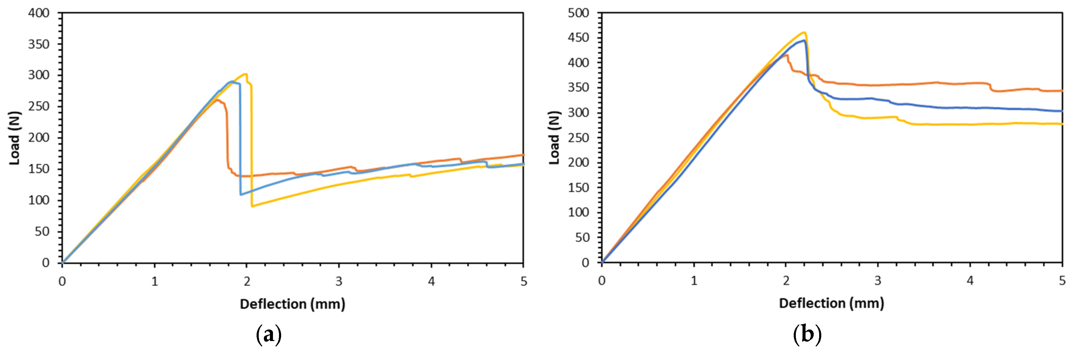
3.1. Flexural Test
3.2. Compression Test
4. Discussion
4.1. Flexural Properties
4.2. Compression Properties
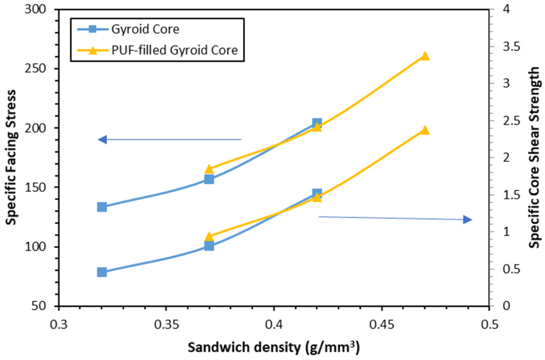
4.3. Specific Mechanical Properties
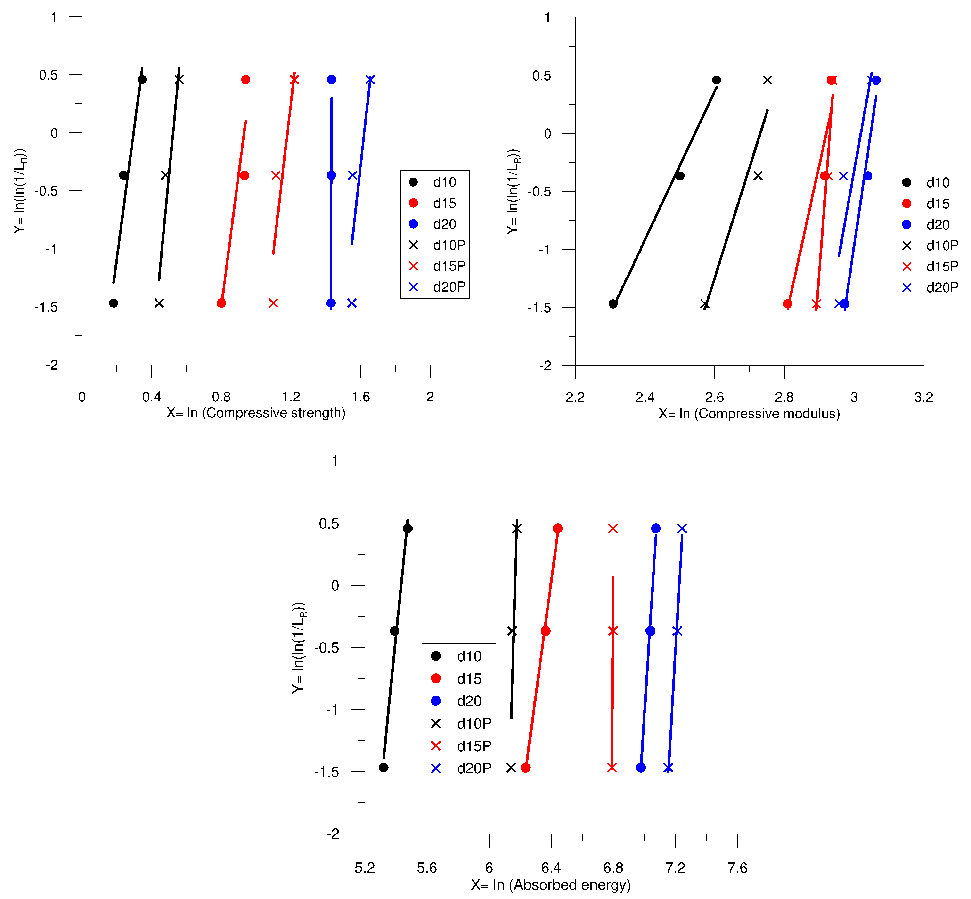
4.4. Statistical Analysis
5. Conclusions
Author Contributions
Funding
Institutional Review Board Statement
Data Availability Statement
Acknowledgments
Conflicts of Interest
References
- Henderson, R.P.; Martins, J.R.R.A.; Perez, R.E. Aircraft Conceptual Design for Optimal Environmental Performance. Aeronaut. J. 2012, 116, 1–22. [Google Scholar] [CrossRef]
- He, M.; Hu, W. A Study on Composite Honeycomb Sandwich Panel Structure. Mater. Des. 2008, 29, 709–713. [Google Scholar] [CrossRef]
- Al Rifaie, M.; Abdulhadi, H.; Mian, A. Advances in Mechanical Metamaterials for Vibration Isolation: A Review. Adv. Mech. Eng. 2022, 14, 16878132221082872. [Google Scholar] [CrossRef]
- Le, V.T.; Ha, N.S.; Goo, N.S. Advanced Sandwich Structures for Thermal Protection Systems in Hypersonic Vehicles: A Review. Compos. B Eng. 2021, 226, 109301. [Google Scholar] [CrossRef]
- Brenken, B.; Barocio, E.; Favaloro, A.; Kunc, V.; Pipes, R.B. Fused Filament Fabrication of Fiber-Reinforced Polymers: A Review. Addit. Manuf. 2018, 21, 1–16. [Google Scholar] [CrossRef]
- Joseph, A.; Mahesh, V.; Mahesh, V.; Harursampath, D.; Mallesha, V. Role of 3D Printing in the Fabrication of Composite Sandwich Structures. In Sandwich Composites: Fabrication and Characterization; CRC Press: Boca Raton, FL, USA, 2022; pp. 349–375. ISBN 9781000531688. [Google Scholar]
- Chen, Y.; Ma, Y.; Yin, Q.; Pan, F.; Cui, C.; Zhang, Z.; Liu, B. Advances in Mechanics of Hierarchical Composite Materials. Compos. Sci. Technol. 2021, 214, 108970. [Google Scholar] [CrossRef]
- Chen, Y.; Jin, Z.; Kang, W.; Liu, Z.; Yang, W.; Li, Y. 3D Printed Bio-Inspired Self-Similar Carbon Fiber Reinforced Composite Sandwich Structures for Energy Absorption. Compos. Sci. Technol. 2024, 248, 110453. [Google Scholar] [CrossRef]
- Wan, M.; Hu, D.; Zhang, H.; Pi, B.; Ye, X. Crashworthiness Study of Tubular Lattice Structures Based on Triply Periodic Minimal Surfaces under Quasi-Static Axial Crushing. Compos. Struct. 2024, 327, 117703. [Google Scholar] [CrossRef]
- Al-Ketan, O.; Soliman, A.; AlQubaisi, A.M.; Abu Al-Rub, R.K. Nature-Inspired Lightweight Cellular Co-Continuous Composites with Architected Periodic Gyroidal Structures. Adv. Eng. Mater. 2018, 20, 1700549. [Google Scholar] [CrossRef]
- Michielsen, K.; Stavenga, D.G. Gyroid Cuticular Structures in Butterfly Wing Scales: Biological Photonic Crystals. J. R. Soc. Interface 2007, 5, 85–94. [Google Scholar] [CrossRef]
- Pelanconi, M.; Ortona, A. Nature-Inspired, Ultra-Lightweight Structures with Gyroid Cores Produced by Additive Manufacturing and Reinforced by Unidirectional Carbon Fiber Ribs. Materials 2019, 12, 4134. [Google Scholar] [CrossRef] [PubMed]
- Ayrilmis, N.; Nagarajan, R.; Kuzman, M.K. Effects of the Face/Core Layer Ratio on the Mechanical Properties of 3d Printed Wood/Polylactic Acid (Pla) Green Biocomposite Panels with a Gyroid Core. Polymers 2020, 12, 2929. [Google Scholar] [CrossRef] [PubMed]
- Fashanu, O.; Rangapuram, M.; Abutunis, A.; Newkirk, J.; Chandrashekhara, K.; Misak, H.; Klenosky, D. Mechanical Performance of Sandwich Composites with Additively Manufactured Triply Periodic Minimal Surface Cellular Structured Core. J. Sandw. Struct. Mater. 2021, 24, 1133–1151. [Google Scholar] [CrossRef]
- Celiński, M.; Sałasińska, K.; Mizera, K.; Kozikowski, P. Fire Behavior of Sandwich Panels with Different Cores. In Advances in the Toxicity of Construction and Building Materials; Woodhead Publishing: Sawston, UK, 2022; pp. 137–170. ISBN 9780128245330. [Google Scholar]
- Castanie, B.; Bouvet, C.; Ginot, M. Review of Composite Sandwich Structure in Aeronautic Applications. Compos. Part C Open Access 2020, 1, 100004. [Google Scholar] [CrossRef]
- Krzyzak, A.; Mazur, M.; Gajewski, M.; Drozd, K.; Komorek, A.; Przybyłek, P. Sandwich Structured Composites for Aeronautics: Methods of Manufacturing Affecting Some Mechanical Properties. Int. J. Aerosp. Eng. 2016, 2016, 7816912. [Google Scholar] [CrossRef]
- Sugiyama, K.; Matsuzaki, R.; Ueda, M.; Todoroki, A.; Hirano, Y. 3D Printing of Composite Sandwich Structures Using Continuous Carbon Fiber and Fiber Tension. Compos. Part A Appl. Sci. Manuf. 2018, 113, 114–121. [Google Scholar] [CrossRef]
- Zaharia, S.M.; Enescu, L.A.; Pop, M.A. Mechanical Performances of Lightweight Sandwich Structures Produced by Material Extrusion-Based Additive Manufacturing. Polymers 2020, 12, 1740. [Google Scholar] [CrossRef] [PubMed]
- Haldar, A.K.; Managuli, V.; Munshi, R.; Agarwal, R.S.; Guan, Z.W. Compressive Behaviour of 3D Printed Sandwich Structures Based on Corrugated Core Design. Mater. Today Commun. 2021, 26, 101725. [Google Scholar] [CrossRef]
- Peng, C.; Fox, K.; Qian, M.; Nguyen-Xuan, H.; Tran, P. 3D Printed Sandwich Beams with Bioinspired Cores: Mechanical Performance and Modelling. Thin-Walled Struct. 2021, 161, 107471. [Google Scholar] [CrossRef]
- ASTM C393/C393M-20; Standard Test Method for Core Shear Properties of Sandwich Constructions by Beam Flexure. ASTM International: West Conshohocken, PA, USA, 2020. [CrossRef]
- ASTM C365/C365M-22; Standard Test Method for Flatwise Compressive Properties of Sandwich Cores. ASTM International: West Conshohocken, PA, USA, 2022. [CrossRef]
- Selmy, A.I.; Abd El-Baky, M.A.; Ghazy, M.R.; Kamel, M. Flexural Fatigue Performance of Glass Fiber/Epoxy Step-Wise Functionally and Non-Functionally Graded Composites of Different Structures. Int. Polym. Process. 2017, 32, 298–307. [Google Scholar] [CrossRef]
- Abd El-baky, M.A. Impact Performance of Hybrid Laminated Composites with Statistical Analysis. Iran. Polym. J. Engl. Ed. 2018, 27, 445–459. [Google Scholar] [CrossRef]
- Awd Allah, M.M.; Abd El-baky, M.A.; Alshahrani, H.; Sebaey, T.A.; Hegazy, D.A. Energy Absorption Capability of Laterally Loaded Glass/Epoxy Tubular Components Containing Halloysite Nanotubes. J. Compos. Mater. 2023, 57, 4307–4325. [Google Scholar] [CrossRef]
- Alshahrani, H.; Sebaey, T.A.; Hegazy, D.A.; Abd El-baky, M.A. Effects of Halloysite Clay Nanotubes on the Energy Absorption and Failure Mechanisms of Glass/Epoxy Composite Tubes Subjected to Quasi-Static Axial Crushing. Polym. Compos. 2022, 43, 7099–7117. [Google Scholar] [CrossRef]
- Abd El-Aziz, K.; Hegazy, D.A.; Abd El-baky, M.A. Impact of Montmorillonite Clay on Energy Absorption Capability of Glass/Epoxy Composite Tubes: An Experimental Study. Fibers Polym. 2022, 23, 2284–2298. [Google Scholar] [CrossRef]
- Selmy, A.I.; Azab, N.A.; El-Baky, M.A. Statistical Analysis of Monotonic Mechanical Properties for Unidirectional Glass Fiber (U)/Random Glass Fiber (R)/Epoxy Hybrid and Non-Hybrid Polymeric Composites. J. Compos. Mater. 2014, 48, 455–469. [Google Scholar] [CrossRef]
- Tao, Y.; Li, P.; Zhang, H.; Shi, S.Q.; Zhang, J.; Yin, Q. Compression and Flexural Properties of Rigid Polyurethane Foam Composites Reinforced with 3D-Printed Polylactic Acid Lattice Structures. Compos. Struct. 2022, 279, 114866. [Google Scholar] [CrossRef]
- Junaedi, H.; Khan, T.; Sebaey, T.A. Characteristics of Carbon-Fiber-Reinforced Polymer Face Sheet and Glass-Fiber-Reinforced Rigid Polyurethane Foam Sandwich Structures under Flexural and Compression Tests. Materials 2023, 16, 5101. [Google Scholar] [CrossRef]
- Salleh, Z.; Islam, M.M.; Epaarachchi, J.A.; Su, H. Mechanical Properties of Sandwich Composite Made of Syntactic Foam Core and GFRP Skins. AIMS Mater. Sci. 2016, 3, 1704–1727. [Google Scholar] [CrossRef]
- Manalo, A.C. Behaviour of Fibre Composite Sandwich Structures under Short and Asymmetrical Beam Shear Tests. Compos. Struct. 2013, 99, 339–349. [Google Scholar] [CrossRef]
- Lu, W.; Liu, H.; Waqas, A.; Long, L. Study on Buckling Behavior of Multilayer Pyramid Lattice Structures. Mech. Adv. Mater. Struct. 2023, 1–11. [Google Scholar] [CrossRef]
- Peng, C.; Tran, P.; Mouritz, A.P. Compression and Buckling Analysis of 3D Printed Carbon Fibre-Reinforced Polymer Cellular Composite Structures. Compos. Struct. 2022, 300, 116167. [Google Scholar] [CrossRef]
- Lee, S.M.; Tsotsis, T.K. Indentation Failure Behavior of Honeycomb Sandwich Panels. Compos. Sci. Technol. 2000, 60, 1147–1159. [Google Scholar] [CrossRef]
- Xia, F.; Durandet, Y.; Tan, P.J.; Ruan, D. Three-Point Bending Performance of Sandwich Panels with Various Types of Cores. Thin-Walled Struct. 2022, 179, 109723. [Google Scholar] [CrossRef]
- Awd Allah, M.M.; Hegazy, D.A.; Alshahrani, H.; Sebaey, T.A.; Abd El-baky, M.A. Exploring the Effect of Nanoclay Addition on Energy Absorption Capability of Laterally Loaded Glass/Epoxy Composite Tubes. Polym. Compos. 2023; early view. [Google Scholar] [CrossRef]


| Name Tag | Designed Relative Density of Gyroid Core (%) | Bulk Density of Gyroid Core (g/cm3) | PUF Filled |
|---|---|---|---|
| d10 | 10 | 0.13 | No |
| d15 | 15 | 0.19 | No |
| d20 | 20 | 0.25 | No |
| d10P | 10 | 0.13 | Yes |
| d15P | 15 | 0.19 | Yes |
| d20P | 20 | 0.25 | Yes |
| Name Tag | Sandwich Density (g/mm3) | Max. Load (N) | Deflection at Max. Load (mm) |
|---|---|---|---|
| d10 | 0.32 ± 0.01 | 282 ± 19 | 1.96 ± 0.25 |
| d15 | 0.37 ± 0.01 | 418 ± 30 | 1.5 ± 0.21 |
| d20 | 0.42 ± 0.01 | 681 ± 42 | 1.65 ± 0.17 |
| d10P | 0.37 ± 0.01 | 441 ± 23 | 2.14 ± 0.11 |
| d15P | 0.42 ± 0.01 | 651 ± 105 | 1.97 ± 0.3 |
| d20P | 0.47 ± 0.01 | 1018 ± 64 | 2.16 ± 0.11 |
| Name Tag | Data | Facing Stress (MPa) | Core Shear Strength (MPa) |
|---|---|---|---|
| d10 | α | 17.34 | 17.34 |
| β | 25.89 | 0.44 | |
| (M) | 25.11 | 0.43 | |
| (SD) | 1.79 | 0.03 | |
| (CV) % | 7.11 | 7.114 | |
| Eqn. | Y = 17.34 X − 56.42 | Y = 17.340 X + 14.23 | |
| d15 | α | 17.23 | 17.23 |
| β | 38.40 | 0.65 | |
| (M) | 37.23 | 0.63 | |
| (SD) | 2.67 | 0.05 | |
| (CV) % | 7.16 | 7.16 | |
| Eqn. | Y = 17.23 X − 62.84 | Y = 17.23 X + 7.35 | |
| d20 | α | 18.08 | 18.08 |
| β | 62.80 | 1.07 | |
| (M) | 60.98 | 1.04 | |
| (SD) | 4.17 | 0.07 | |
| (CV) % | 6.84 | 6.83 | |
| Eqn. | Y = 18.08 X − 74.84 | Y = 18.08 X − 1.18 | |
| d10P | α | 18.24 | 18.24 |
| β | 41.52 | 0.71 | |
| (M) | 40.33 | 0.69 | |
| (SD) | 2.73 | 0.05 | |
| (CV) % | 6.77 | 6.77 | |
| Eqn. | Y = 18.24 X − 67.98 | Y = 18.24 X + 6.36 | |
| d15P | α | 5.41 | 5.41 |
| β | 64.64 | 1.10 | |
| (M) | 59.61 | 1.01 | |
| (SD) | 12.71 | 0.22 | |
| (CV) % | 21.32 | 21.32 | |
| Eqn. | Y = 5.41 X − 22.54 | Y = 5.41 X − 0.51 | |
| d20P | α | 14.27 | 14.27 |
| β | 96.62 | 1.64 | |
| (M) | 93.15 | 1.58 | |
| (SD) | 7.99 | 0.14 | |
| (CV) % | 8.58 | 8.58 | |
| Eqn. | Y = 14.27 X − 65.22 | Y = 14.27 X − 7.08 |
| Name Tag | Data | Compression Strength (MPa) | Compression Modulus (kPa) | Energy Absorbed (kJ/m3) |
|---|---|---|---|---|
| d10 | α | 11.28 | 6.39 | 12.31 |
| β | 1.35 | 12.73 | 228.82 | |
| (M) | 1.29 | 11.85 | 219.48 | |
| (SD) | 0.14 | 2.17 | 21.70 | |
| (CV) % | 10.73 | 18.28 | 9.89 | |
| Eqn. | Y = 11.28 X − 3.35 | Y = 6.39 X − 16.25 | Y = 12.31 X − 66.86 | |
| d15 | α | 11.45 | 13.66 | 9.24 |
| β | 2.54 | 18.55 | 599.77 | |
| (M) | 2.43 | 17.86 | 568.63 | |
| (SD) | 0.26 | 1.60 | 71.20 | |
| (CV) % | 10.58 | 8.94 | 12.52 | |
| Eqn. | Y = 11.45 X − 10.66 | Y = 13.66 X − 39.89 | Y = 9.24 X − 59.12 | |
| d20 | α | 634.34 | 20.40 | 19.54 |
| β | 4.19 | 21.07 | 1156.82 | |
| (M) | 4.18 | 20.52 | 1125.51 | |
| (SD) | 0.001 | 1.25 | 71.31 | |
| (CV) % | 0.02 | 6.08 | 6.34 | |
| Eqn. | Y = 634.34 X − 908.52 | Y = 20.40 X − 62.16 | Y = 19.54 X − 137.80 | |
| d10P | α | 15.73 | 9.51 | 43.53 |
| β | 1.69 | 15.35 | 476.58 | |
| (M) | 1.63 | 14.57 | 470.50 | |
| (SD) | 0.13 | 1.84 | 13.65 | |
| (CV) % | 7.81 | 12.62 | 2.90 | |
| Eqn. | Y = 15.73 X − 8.23 | Y = 9.51 X − 25.97 | Y = 43.53 X − 268.41 | |
| d15P | α | 12.82 | 39.41 | 267.97 |
| β | 3.25 | 18.74 | 895.53 | |
| (M) | 3.13 | 18.47 | 893.61 | |
| (SD) | 0.30 | 0.59 | 4.01 | |
| (CV) % | 9.51 | 3.19 | 0.45 | |
| Eqn. | Y = 12.82 X − 15.12 | Y= 39.41 X − 115.50 | Y = 267.97 X − 1821.49 | |
| d20P | α | 13.50 | 16.80 | 21.51 |
| β | 5.06 | 20.48 | 1373.26 | |
| (M) | 4.87 | 19.85 | 1339.22 | |
| (SD) | 0.40 | 1.46 | 77.32 | |
| (CV) % | 9.04 | 7.33 | 5.77 | |
| Eqn. | Y = 13.50 X − 21.88 | Y = 16.80 X − 50.72 | Y = 21.51 X − 155.37 |
| Name Tag | Flexural Test | Compression Test | |||
|---|---|---|---|---|---|
| Specific Facing Stress (MPa.mm3/g) | Specific Core Shear Stress (MPa.mm3/g) | Specific Compression Strength (MPa.mm3/g) | Specific Compression Modulus (kPa.mm3/g) | Specific Energy Absorbed (kJ.mm3/g) | |
| d10 | 78.47 | 1.33 | 4.02 | 37.02 | 685.86 |
| d15 | 100.63 | 1.71 | 6.56 | 48.26 | 1536.85 |
| d20 | 145.18 | 2.47 | 9.96 | 48.86 | 2679.78 |
| d10P | 109.00 | 1.85 | 4.41 | 39.38 | 1271.62 |
| d15P | 141.94 | 2.41 | 7.44 | 43.98 | 2127.63 |
| d20P | 198.20 | 3.37 | 10.35 | 42.23 | 2849.39 |
Disclaimer/Publisher’s Note: The statements, opinions and data contained in all publications are solely those of the individual author(s) and contributor(s) and not of MDPI and/or the editor(s). MDPI and/or the editor(s) disclaim responsibility for any injury to people or property resulting from any ideas, methods, instructions or products referred to in the content. |
© 2024 by the authors. Licensee MDPI, Basel, Switzerland. This article is an open access article distributed under the terms and conditions of the Creative Commons Attribution (CC BY) license (https://creativecommons.org/licenses/by/4.0/).
Share and Cite
Junaedi, H.; Abd El-baky, M.A.; Awd Allah, M.M.; Sebaey, T.A. Mechanical Characteristics of Sandwich Structures with 3D-Printed Bio-Inspired Gyroid Structure Core and Carbon Fiber-Reinforced Polymer Laminate Face-Sheet. Polymers 2024, 16, 1698. https://doi.org/10.3390/polym16121698
Junaedi H, Abd El-baky MA, Awd Allah MM, Sebaey TA. Mechanical Characteristics of Sandwich Structures with 3D-Printed Bio-Inspired Gyroid Structure Core and Carbon Fiber-Reinforced Polymer Laminate Face-Sheet. Polymers. 2024; 16(12):1698. https://doi.org/10.3390/polym16121698
Chicago/Turabian StyleJunaedi, Harri, Marwa A. Abd El-baky, Mahmoud M. Awd Allah, and Tamer A. Sebaey. 2024. "Mechanical Characteristics of Sandwich Structures with 3D-Printed Bio-Inspired Gyroid Structure Core and Carbon Fiber-Reinforced Polymer Laminate Face-Sheet" Polymers 16, no. 12: 1698. https://doi.org/10.3390/polym16121698