
Investigation of Friction Stir Welding of Additively Manufactured Biocompatible Thermoplastics Using Stationary Shoulder and Assisted Heating

 , ,
, ,  and
and
Abstract

1. Introduction
2. Materials and Methods
2.1. Materials
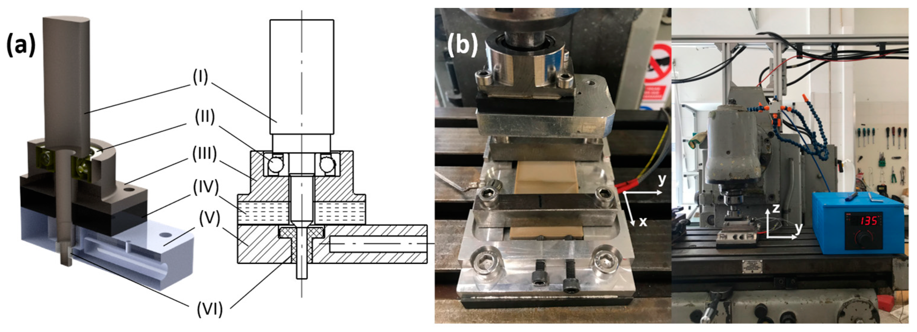
2.2. FSW Apparatus
2.3. Experimental Procedure
2.4. SS-FSW Parameters and Assisted Heating
2.5. Thermal Analysis
3. Results and Discussion
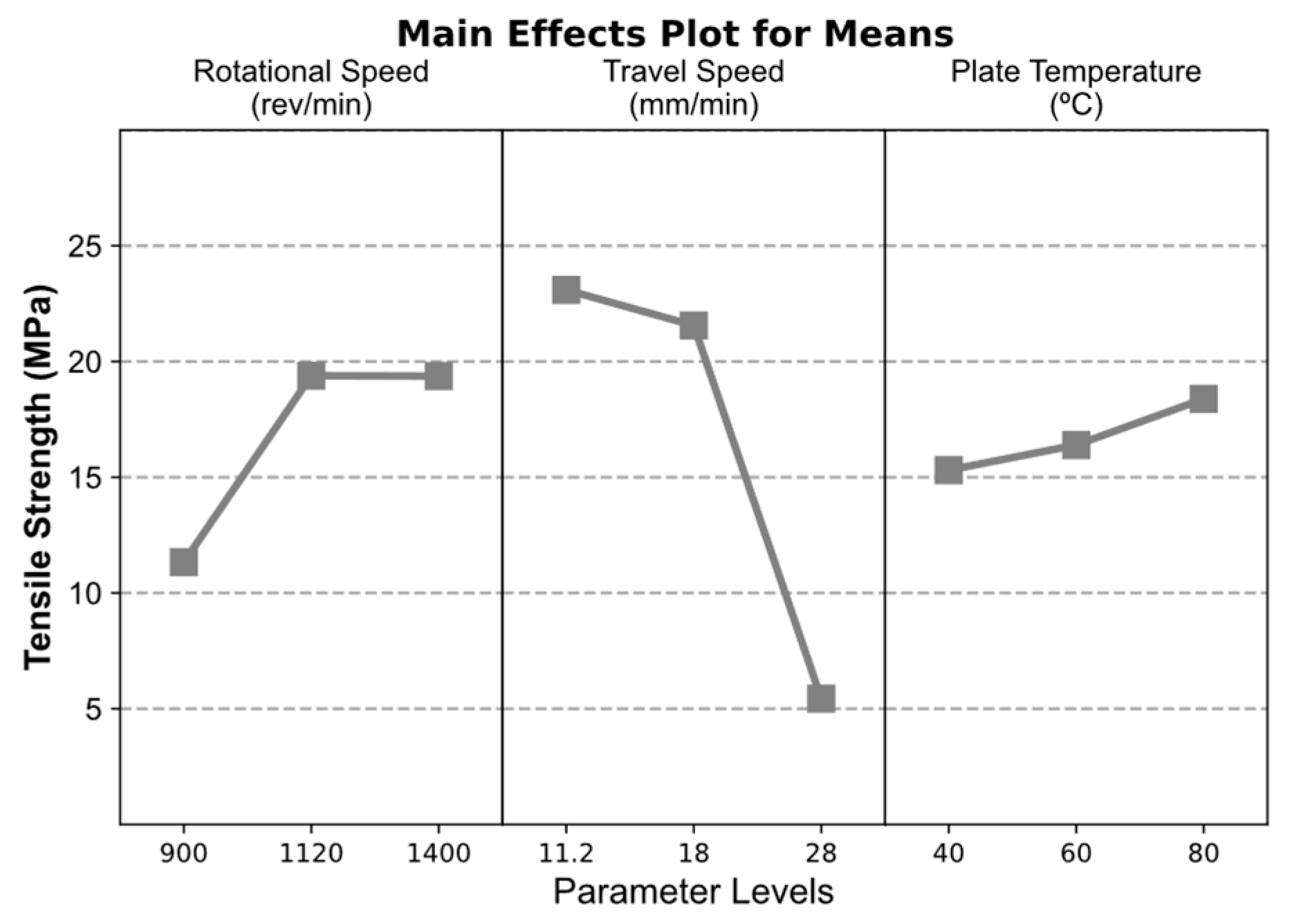
3.1. FSW Parameters on the Relative Weld Efficiency of 3D-Printed PLA
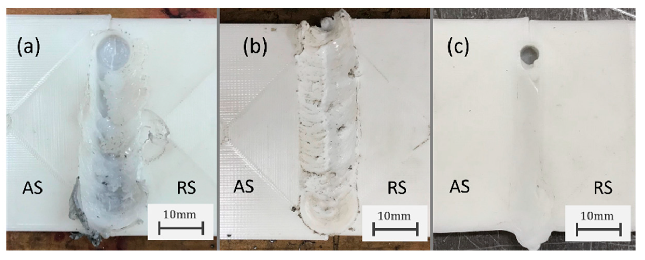
3.2. Assisted Heating SS-FSW of 3D-Printed PEEK
4. Conclusions
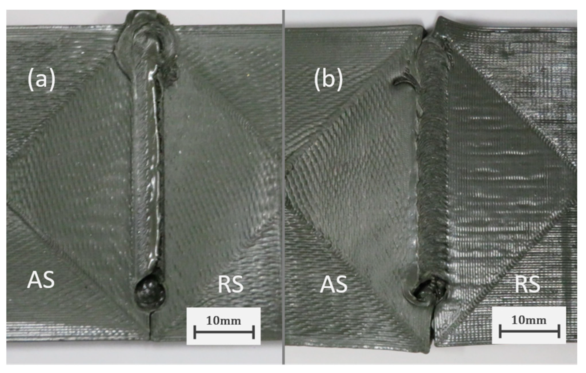
- The use of stationary shoulder tools for the FSW of thermoplastics is more effective in containing the material in the stirred region and reduces material removal and flash defects observed with rotating shoulder tools;
- The lowest tested travel speed of 11.2 reduced the presence and size of void defects appearing on the retreating side and resulted in the highest joint efficiencies;
- The parameter combination that maximizes the average strength of the weld corresponds to intermediate–high RS of 1120–1400 revmin−1, low TS of 11.2 mmmin−1, and high BPT of 80 °C. A significant contribution of about 58% is attributed to travel speed while backing plate temperature was not statistically significant in the strength of the welds;
- The highest strength of 38.2 MPa corresponding to a joint efficiency of 93.8% was obtained with 1400 revmin−1, 11.2 mmmin−1, and 80 °C which is higher than the results obtained in previous research. Nevertheless, these parameters resulted in an average tensile strength of 30.8 MPa and joint efficiency of 75.6%;
- The higher heat input required for the SS-FSW of high-temperature thermoplastics such as PEEK can be provided through assisted heating. This can improve material flow in the stirred region since the highest tested backing plate temperature of 165 °C was found to reduce void defects appearing in the retreating side;
- The use of a heated backing plate is a more effective configuration for the assisted heating compared to the heated shoulder in the “hot shoe” configuration since it allows for a more controlled cooling of the weld and thus can promote crystallization of FSW-processed PEEK.
Author Contributions
Funding
Institutional Review Board Statement
Data Availability Statement
Acknowledgments
Conflicts of Interest
References
- Sachs, E.; Cima, M.; Cornie, J.; Brancazio, D.; Bredt, J.; Curodeau, A.; Fan, T.; Khanuja, S.; Lauder, A.; Lee, J.; et al. Three-Dimensional Printing: The Physics and Implications of Additive Manufacturing. CIRP Ann. Manuf. Technol. 1993, 42, 257–260. [Google Scholar] [CrossRef]
- Gibson, I.; Rosen, D.; Stucker, B.; Khorasani, M. Additive Manufacturing Technologies, 3rd ed.; Springer Nature Switzerland AG: Cham, Switzerland, 2021; ISBN 978-3-030-56127-7. [Google Scholar]
- Haryńska, A.; Carayon, I.; Kosmela, P.; Szeliski, K.; Łapiński, M.; Pokrywczyńska, M.; Kucińska-Lipka, J.; Janik, H. A Comprehensive Evaluation of Flexible FDM/FFF 3D Printing Filament as a Potential Material in Medical Application. Eur. Polym. J. 2020, 138, 109958. [Google Scholar] [CrossRef]
- Garcia, J.; Yang, Z.L.; Mongrain, R.; Leask, R.L.; Lachapelle, K. 3D Printing Materials and Their Use in Medical Education: A Review of Current Technology and Trends for the Future. BMJ Simul. Technol. Enhanc. Learn. 2018, 4, 27–40. [Google Scholar] [CrossRef] [PubMed]
- Sadeghzade, S.; Hooshiar, M.H.; Akbari, H.; Tajer, M.H.M.; Sahneh, K.K.; Ziaei, S.Y.; Jalali, F.; Akouchakian, E. Recent Advances in Organ-on-a-Chip Models: How Precision Engineering Integrates Cutting Edge Technologies in Fabrication and Characterization; Elsevier Ltd.: Amsterdam, The Netherlands, 2024; Volume 38, ISBN 8415683111. [Google Scholar]
- Galateanu, B.; Hudita, A.; Biru, E.I.; Iovu, H.; Zaharia, C.; Simsensohn, E.; Costache, M.; Petca, R.C.; Jinga, V. Applications of Polymers for Organ-on-Chip Technology in Urology. Polymers 2022, 14, 1668. [Google Scholar] [CrossRef] [PubMed]
- Middleton, J.C.; Tipton, A.J. Synthetic Biodegradable Polymers as Orthopedic Devices. Biomaterials 2000, 21, 2335–2346. [Google Scholar] [CrossRef] [PubMed]
- Athanasiou, K.A.; Niederauer, G.G.; Agrawal, C.M. Biocompatibility and Clinical Applications of Polylactic Acid/Polyglycolic Acid Copolymers. Biomaterials 1996, 17, 93–102. [Google Scholar] [CrossRef] [PubMed]
- Destefano, V.; Khan, S.; Tabada, A. Applications of PLA in Modern Medicine. Eng. Regen. 2020, 1, 76–87. [Google Scholar] [CrossRef] [PubMed]
- Kurtz, S.M. An Overview of PEEK Biomaterials. In PEEK Biomaterials Handbook; Elsevier Inc.: Amsterdam, The Netherlands, 2012; pp. 1–7. ISBN 13: 978-1-4377-4463-7. [Google Scholar]
- Green, S.; Schlegel, J. A Polyaryletherketone Biomaterial for Use in Medical Implant Applications. Polym. Med. Ind. Proc. Conf. Held Bruss. 2001, 1–7. [Google Scholar]
- Hussain, R.K.; Majeed, A.A. Thermoplastics Polymers Friction Stir Welding: Review. Int. J. Eng. Technol. 2018, 7, 4612–4616. [Google Scholar] [CrossRef]
- Thomas, W.M.; Nicholas, E.D.; Needham, J.C.; Murch, M.G.; Temple-smith, P.; Dawes, C.J. Friction Stir Butt Welding. Patent Application No. PCT/GB92/02203. G.B. Patent Application No.9125978, 8 December 1991. [Google Scholar]
- Ferreira, P.M.; Machado, M.A.; Carvalho, M.S.; Vidal, C. Granting Sensorial Properties to Metal Parts through Friction Stir Processing. Meas. J. Int. Meas. Confed. 2023, 207, 112405. [Google Scholar] [CrossRef]
- Vidal, C.; Alves, P.; Alves, M.M.; Jo, M.; Fernandes, H.; Grenho, L.; In, P.L.; Ferreira, F.B.; Santos, T.G.; Santos, C. Fabrication of a Biodegradable and Cytocompatible Magnesium/Nanohydroxyapatite/Fluorapatite Composite by Upward Friction Stir Processing for Biomedical Applications. J. Mech. Behav. Biomed. Mater. 2022, 129, 105137. [Google Scholar] [CrossRef]
- Arici, A.; Sinmaz, T. Effects of Double Passes of the Tool on Friction Stir Welding of Polyethylene. J. Mater. Sci. 2005, 40, 3313–3316. [Google Scholar] [CrossRef]
- Nelson, T.W.; Sorenson, C.D.; Johns, C.J. Friction Stir Welding of Polymeric Materials 2004. U.S. Patent No. 6,811,632, 2 November 2004. [Google Scholar]
- Ishihama, H.; Ishii, K.; Nagai, S.; Kakinuma, H.; Sasaki, A.; Yoshioka, K.; Kuramoto, T.; Shiono, Y.; Funao, H.; Isogai, N.; et al. An Antibacterial Coated Polymer Prevents Biofilm Formation and Implant-Associated Infection. Sci. Rep. 2021, 11, 1–12. [Google Scholar] [CrossRef]
- Hosseini Hooshiar, M.; Badkoobeh, A.; Kolahdouz, S.; Tadayonfard, A.; Mozaffari, A.; Nasiri, K.; Salari, S.; Safaralizadeh, R.; Yasamineh, S. The Potential Use of Nanozymes as an Antibacterial Agents in Oral Infection, Periodontitis, and Peri-Implantitis. J. Nanobiotechnology 2024, 22, 1–35. [Google Scholar] [CrossRef]
- Lambiase, F.; Paoletti, A.; Grossi, V.; Di Ilio, A. Analysis of Loads, Temperatures and Welds Morphology in FSW of Polycarbonate. J. Mater. Process. Technol. 2019, 266, 639–650. [Google Scholar] [CrossRef]
- Eslami, S.; Tavares, P.J.; Moreira, P.M.G.P. Friction Stir Welding Tooling for Polymers: Review and Prospects. Int. J. Adv. Manuf. Technol. 2017, 89, 1677–1690. [Google Scholar] [CrossRef]
- Payganeh, G.H.; Mostafa Arab, N.B.; Dadgar Asl, Y.; Ghasemi, F.A.; Saeidi Boroujeni, M. Effects of Friction Stir Welding Process Parameters on Appearance and Strength of Polypropylene Composite Welds. Int. J. Phys. Sci. 2011, 6, 4595–4601. [Google Scholar] [CrossRef]
- Aghajani Derazkola, H.; Simchi, A.; Lambiase, F. Friction Stir Welding of Polycarbonate Lap Joints: Relationship between Processing Parameters and Mechanical Properties. Polym. Test. 2019, 79, 105999. [Google Scholar] [CrossRef]
- Squeo, E.A.; Bruno, G.; Guglielmotti, A.; Quadrini, F. Friction Stir Welding of Polyethylene Sheets. In Annals of ”Dunarea de Jos” University of Galati; University of Galati: Galați, Romania, 2009; Volume 27, pp. 241–246. [Google Scholar]
- Vijendra, B.; Sharma, A. Induction Heated Tool Assisted Friction-Stir Welding (i-FSW): A Novel Hybrid Process for Joining of Thermoplastics. J. Manuf. Process. 2015, 20, 234–244. [Google Scholar] [CrossRef]
- Banjare, P.N.; Sahlot, P.; Arora, A. An Assisted Heating Tool Design for FSW of Thermoplastics. J. Mater. Process. Technol. 2017, 239, 83–91. [Google Scholar] [CrossRef]
- Aydin, M. Effects of Welding Parameters and Pre-Heating on the Friction Stir Welding of UHMW-Polyethylene. Polym. Plast. Technol. Eng. 2010, 49, 595–601. [Google Scholar] [CrossRef]
- Kiss, Z.; Czigány, T. Microscopic Analysis of the Morphology of Seams in Friction Stir Welded Polypropylene. Express Polym. Lett. 2012, 6, 54–62. [Google Scholar] [CrossRef]
- Pirizadeh, M.; Azdast, T.; Rash Ahmadi, S.; Mamaghani Shishavan, S.; Bagheri, A. Friction Stir Welding of Thermoplastics Using a Newly Designed Tool. Mater. Des. 2014, 54, 342–347. [Google Scholar] [CrossRef]
- Simoes, F.; Rodrigues, D.M. Material Flow and Thermo-Mechanical Conditions during Friction Stir Welding of Polymers: Literature Review, Experimental Results and Empirical Analysis. Mater. Des. 2014, 59, 344–351. [Google Scholar] [CrossRef]
- Kumar, R.; Singh, R.; Ahuja, I.P.S.; Penna, R.; Feo, L. Weldability of Thermoplastic Materials for Friction Stir Welding- A State of Art Review and Future Applications. Compos. Part B Eng. 2018, 137, 1–15. [Google Scholar] [CrossRef]
- Huang, Y.; Meng, X.; Xie, Y.; Wan, L.; Lv, Z.; Cao, J.; Feng, J. Friction Stir Welding/Processing of Polymers and Polymer Matrix Composites. Compos. Part A Appl. Sci. Manuf. 2018, 105, 235–257. [Google Scholar] [CrossRef]
- Azarsa, E.; Mostafapour, A. Experimental Investigation on Flexural Behavior of Friction Stir Welded High Density Polyethylene Sheets. J. Manuf. Process. 2014, 16, 149–155. [Google Scholar] [CrossRef]
- Mendes, N.; Loureiro, A.; Martins, C.; Neto, P.; Pires, J.N. Morphology and Strength of Acrylonitrile Butadiene Styrene Welds Performed by Robotic Friction Stir Welding. Mater. Des. 2014, 64, 81–90. [Google Scholar] [CrossRef]
- Bagheri, A.; Azdast, T.; Doniavi, A. An Experimental Study on Mechanical Properties of Friction Stir Welded ABS Sheets. Mater. Des. 2013, 43, 402–409. [Google Scholar] [CrossRef]
- Sharma, A.K.R.; Roy Choudhury, M.; Debnath, K. Experimental Investigation of Friction Stir Welding of PLA. Weld. World 2020, 64, 1011–1021. [Google Scholar] [CrossRef]
- Zafar, A.; Awang, M.; Khan, S.R. 3rd International Conference on Mechanical, Manufacturing and Process Plant Engineering (ICMMPE 2017). IOP Conf. Ser. Mater. Sci. Eng. 2018, 328, 011001. [Google Scholar] [CrossRef]
- Bajakke, P.A.; Malik, V.R.; Deshpande, A.S. Particulate Metal Matrix Composites and Their Fabrication via Friction Stir Processing–a Review. Mater. Manuf. Process. 2019, 34, 833–881. [Google Scholar] [CrossRef]
- Nath, R.K.; Maji, P.; Barma, J.D. Joining of Advance Engineering Thermoplastic Using Novel Self-Heated FSW Tool. Jom 2021, 73, 1774–1785. [Google Scholar] [CrossRef]
- Jose, J.V.; Panneerselvam, K. Joining of PEEK Plates by Friction Stir Welding Process. Mater. Today Proc. 2020, 39, 1635–1639. [Google Scholar] [CrossRef]
- Gagliardi, F.; Ambrogio, G.; Conte, R.; Russo, P. Investigation of Friction Stir Forming for Mechanical Interlocking High-Performance Polymers and Aluminium Sheets. Manuf. Lett. 2021, 27, 31–38. [Google Scholar] [CrossRef]
- Khadka, P.; Varglund, S.; Akinwamide, S.; Vilaça, P. Characterization of Friction Stir—Based Linear Continuous Joining of Aluminium Alloy to Structural Polymer. Weld. World 2023, 68, 71–90. [Google Scholar] [CrossRef]
- Huang, Y.; Meng, X.; Wang, Y.; Xie, Y.; Zhou, L. Joining of Aluminum Alloy and Polymer via Friction Stir Lap Welding. J. Mater. Process. Technol. 2018, 257, 148–154. [Google Scholar] [CrossRef]
- Dong, H.; Tang, Z.; Li, P.; Wu, B.; Hao, X.; Ma, C. Friction Stir Spot Welding of 5052 Aluminum Alloy to Carbon Fiber Reinforced Polyether Ether Ketone Composites. Mater. Des. 2021, 201, 109495. [Google Scholar] [CrossRef]
- Huang, Y.; Meng, X.; Xie, Y.; Li, J.; Wan, L. Joining of Carbon Fiber Reinforced Thermoplastic and Metal via Friction Stir Welding with Co-Controlling Shape and Performance. Compos. Part A Appl. Sci. Manuf. 2018, 112, 328–336. [Google Scholar] [CrossRef]
- Li, J.; Dong, H.; Tang, Z.; Li, P.; Wu, B.; Ma, Y.; Huang, L.; Zhang, L.; Li, C.; Xiong, J. Influence of Surface Pretreatment on the Bonding Mechanism and Mechanical Properties of AA5052/CFRP Friction Stir Spot Welded Joint. J. Manuf. Process. 2023, 105, 112–123. [Google Scholar] [CrossRef]
- Li, M.; Xiong, X.; Ji, S.; Hu, W.; Yue, Y. Achieving High-Quality Metal to Polymer-Matrix Composites Joint via Top-Thermic Solid-State Lap Joining. Compos. Part B Eng. 2021, 219, 108941. [Google Scholar] [CrossRef]
- Almasi, D.; Lau, W.J.; Rasaee, S.; Sharifi, R.; Mozaffari, H.R. Fabrication of a Novel Hydroxyapatite/Polyether Ether Ketone Surface Nanocomposite via Friction Stir Processing for Orthopedic and Dental Applications. Prog. Biomater. 2020, 9, 35–44. [Google Scholar] [CrossRef] [PubMed]
- Almasi, D.; Lau, W.J.; Rasaee, S.; Abbasi, K. Fabrication and in Vitro Study of 3D Novel Porous Hydroxyapatite/Polyether Ether Ketone Surface Nanocomposite. J. Biomed. Mater. Res. Part B Appl. Biomater. 2022, 110, 838–847. [Google Scholar] [CrossRef] [PubMed]
- Vidakis, N.; Petousis, M.; Mountakis, N.; Kechagias, J.D. Material Extrusion 3D Printing and Friction Stir Welding: An Insight into the Weldability of Polylactic Acid Plates Based on a Full Factorial Design. Int. J. Adv. Manuf. Technol. 2022, 121, 3817–3839. [Google Scholar] [CrossRef]
- Parast, M.S.A.; Bagheri, A.; Kami, A.; Azadi, M.; Asghari, V. Bending Fatigue Behavior of Fused Filament Fabrication 3D-Printed ABS and PLA Joints with Rotary Friction Welding. Prog. Addit. Manuf. 2022, 7, 1345–1361. [Google Scholar] [CrossRef]
- Mendes, N.; Loureiro, A.; Martins, C.; Neto, P.; Pires, J.N. Effect of Friction Stir Welding Parameters on Morphology and Strength of Acrylonitrile Butadiene Styrene Plate Welds. Mater. Des. 2014, 58, 457–464. [Google Scholar] [CrossRef]
- Arici, A.; Mert, Ş. Friction Stir Spot Welding of Polypropylene. J. Reinf. Plast. Compos. 2008, 27, 2001–2004. [Google Scholar] [CrossRef]
- Bilici, M.K. Application of Taguchi Approach to Optimize Friction Stir Spot Welding Parameters of Polypropylene. Mater. Des. 2012, 35, 113–119. [Google Scholar] [CrossRef]
- Bilici, M.K.; Yükler, A.I.; Kurtulmuş, M. The Optimization of Welding Parameters for Friction Stir Spot Welding of High Density Polyethylene Sheets. Mater. Des. 2011, 32, 4074–4079. [Google Scholar] [CrossRef]
- Verma, S.; Misra, J.P. Study on Temperature Distribution during Friction Stir Welding of 6082 Aluminum Alloy. Mater. Today Proc. 2017, 4, 1350–1356. [Google Scholar] [CrossRef]
- Senthil, S.M.; Kumar, M.B. Effect of Tool Rotational Speed and Traverse Speed on Friction Stir Welding of 3D-Printed Polylactic Acid Material. Appl. Sci. Eng. Prog. 2021, 15, 1–9. [Google Scholar] [CrossRef]
- Apium PEEK 450 Natural Datasheet. Available online: https://apiumtec.com/en/case-studies-datasheets (accessed on 28 September 2023).
- Gupta, H.; Salovey, R. Thermal Behavior of Transparent Poly(Etheretherketone)(PEEK) Film. Polym. Eng. Sci. 1990, 30, 453–458. [Google Scholar] [CrossRef]
- Regis, M.; Bellare, A.; Pascolini, T.; Bracco, P. Characterization of Thermally Annealed PEEK and CFR-PEEK Composites: Structure-Properties Relationships. Polym. Degrad. Stab. 2017, 136, 121–130. [Google Scholar] [CrossRef]
- Bonmatin, M.; Chabert, F.; Bernhart, G.; Djilali, T. Rheological and Crystallization Behaviors of Low Processing Temperature Poly(Aryl Ether Ketone). J. Appl. Polym. Sci. 2021, 138, 51402. [Google Scholar] [CrossRef]
- Blundell, D.J.; Osborn, B.N. The Morphology of Poly(Aryl-Ether-Ether-Ketone). Polymer 1983, 24, 953–958. [Google Scholar] [CrossRef]
- Chowdhury, S.M.; Chen, D.L.; Bhole, S.D.; Cao, X. Tensile Properties of a Friction Stir Welded Magnesium Alloy: Effect of Pin Tool Thread Orientation and Weld Pitch. Mater. Sci. Eng. A 2010, 527, 6064–6075. [Google Scholar] [CrossRef]
- Panneerselvam, K.; Lenin, K. Joining of Nylon 6 Plate by Friction Stir Welding Process Using Threaded Pin Profile. Mater. Des. 2014, 53, 302–307. [Google Scholar] [CrossRef]
- Zhang, H.W.; Zhang, Z.; Chen, J.T. The Finite Element Simulation of the Friction Stir Welding Process. Mater. Sci. Eng. A 2005, 403, 340–348. [Google Scholar] [CrossRef]
- Tej, B.; Sudeep, C.; Gummadi, K.; Elhattab, K.; Ahlstrom, J.; Sikder, P. In—House Processing of 3D Printable Polyetheretherketone ( PEEK ) Filaments and the Effect of Fused Deposition Modeling Parameters on 3D—Printed PEEK Structures. Int. J. Adv. Manuf. Technol. 2022, 121, 1675–1688. [Google Scholar] [CrossRef]
- Talbott, M.F.; Springer, G.S.; Berglund, L.A. The Effects of Crystallinity on the Mechanical Properties of PEEK Polymer and Graphite Fiber Reinforced PEEK. J. Compos. Mater. 1987, 21, 1056–1081. [Google Scholar] [CrossRef]
- Naffakh, M.; Gómez, M.A.; Ellis, G.; Marco, C. Thermal Properties, Structure and Morphology of PEEK/Thermotropic Liquid Crystalline Polymer Blends. Polym. Int. 2003, 52, 1876–1886. [Google Scholar] [CrossRef]
- Rinaldi, M.; Ghidini, T.; Cecchini, F.; Brandao, A.; Nanni, F. Additive Layer Manufacturing of Poly (Ether Ether Ketone) via FDM. Compos. Part B Eng. 2018, 145, 162–172. [Google Scholar] [CrossRef]


| RS (rev/min) | TS (mm/min) | BPT (°C) | |
|---|---|---|---|
| C1 | 900 | 11.2 | 40 |
| C2 | 900 | 18.0 | 60 |
| C3 | 900 | 28.0 | 80 |
| C4 | 1120 | 11.2 | 80 |
| C5 | 1120 | 18.0 | 40 |
| C6 | 1120 | 28.0 | 60 |
| C7 | 1400 | 11.2 | 60 |
| C8 | 1400 | 18.0 | 80 |
| C9 | 1400 | 28.0 | 40 |
| Tensile Strength (MPa) | Joint Efficiency (%) | |
|---|---|---|
| Base Material | 40.7 ± 1.5 | — |
| C1 | 11.7 ± 1.9 | 28.6 ± 4.7 |
| C2 | 19.2 ± 3.2 | 47.2 ± 7.8 |
| C3 | 3.1 ± 3.8 | 7.7 ± 9.4 |
| C4 | 26.9 ± 2.8 | 66.0 ± 6.9 |
| C5 | 21.2 ± 1.3 | 52.2 ± 3.3 |
| C6 | 10.1 ± 2.1 | 24.7 ± 5.1 |
| C7 | 30.8 ± 11.9 | 75.6 ± 29.2 |
| C8 | 24.22 ± 9.4 | 59.5 ± 23.2 |
| C9 | 3.12 ± 2.4 | 7.7 ± 5.9 |
| Degrees of Freedom | Sum of Squares | Mean Square | F-Value | p-Value | Contribution (%) | |
|---|---|---|---|---|---|---|
| RT | 2 | 388.44 | 194.22 | 4.47 | 0.025 | 12.8 |
| TS | 2 | 1722.47 | 861.23 | 19.81 | 0.000 | 57.0 |
| BPT | 2 | 43.76 | 21.88 | 0.50 | 0.612 | 1.4 |
| Error | 20 | 869.56 | 43.48 | 28.8 | ||
| Total | 26 | 3024.23 | 100.0 |
| AT 28 °C | 149.7 | 293.8 | −33.68 | 344.3 | 36.24 | 27.9% |
| BP 125 °C | 152.7 | 294.8 | −44.04 | 345.5 | 40.57 | 31.2% |
| BP 145 °C | 148.8 | 294.5 | −39.34 | 347.9 | 36.86 | 28.4% |
| BP 165 °C | 145.7 | 294.9 | −42.68 | 344.8 | 37.34 | 28.7% |
| HS 165 °C | 144.7 | 294.4 | −45.90 | 347.6 | 31.02 | 23.9% |
Disclaimer/Publisher’s Note: The statements, opinions and data contained in all publications are solely those of the individual author(s) and contributor(s) and not of MDPI and/or the editor(s). MDPI and/or the editor(s) disclaim responsibility for any injury to people or property resulting from any ideas, methods, instructions or products referred to in the content. |
© 2024 by the authors. Licensee MDPI, Basel, Switzerland. This article is an open access article distributed under the terms and conditions of the Creative Commons Attribution (CC BY) license (https://creativecommons.org/licenses/by/4.0/).
Share and Cite
Rendas, P.; Figueiredo, L.; Melo, P.; Galhano, C.; Vidal, C.; Soares, B.A.R. Investigation of Friction Stir Welding of Additively Manufactured Biocompatible Thermoplastics Using Stationary Shoulder and Assisted Heating. Polymers 2024, 16, 1897. https://doi.org/10.3390/polym16131897
Rendas P, Figueiredo L, Melo P, Galhano C, Vidal C, Soares BAR. Investigation of Friction Stir Welding of Additively Manufactured Biocompatible Thermoplastics Using Stationary Shoulder and Assisted Heating. Polymers. 2024; 16(13):1897. https://doi.org/10.3390/polym16131897
Chicago/Turabian StyleRendas, Pedro, Lígia Figueiredo, Pedro Melo, Carlos Galhano, Catarina Vidal, and Bruno A. R. Soares. 2024. "Investigation of Friction Stir Welding of Additively Manufactured Biocompatible Thermoplastics Using Stationary Shoulder and Assisted Heating" Polymers 16, no. 13: 1897. https://doi.org/10.3390/polym16131897
APA StyleRendas, P., Figueiredo, L., Melo, P., Galhano, C., Vidal, C., & Soares, B. A. R. (2024). Investigation of Friction Stir Welding of Additively Manufactured Biocompatible Thermoplastics Using Stationary Shoulder and Assisted Heating. Polymers, 16(13), 1897. https://doi.org/10.3390/polym16131897