
Hybrid Solid Polymer Electrolytes Based on Epoxy Resins, Ionic Liquid, and Ceramic Nanoparticles for Structural Applications


Abstract
:
1. Introduction
2. Materials and Methods
2.1. Materials
2.2. Methods
2.2.1. Dynamic Mechanical Thermal Analysis (DMTA)
2.2.2. Cyclic Voltammetry (CV) and Linear Sweep Voltammetry (LSV)
2.2.3. Electrochemical Impedance Spectroscopy (EIS)
2.2.4. Chronoamperometry for Lithium Transference Number Calculations (tLi+)
2.2.5. Field-Emission Gun Scanning Electron Microscopy (FEGSEM)
2.3. Solid Polymer Electrolyte Preparation
2.4. Supercapacitor Fabrication
3. Results and Discussion
3.1. Thermomechanical and Morphologycal Characterization of the Electrolytes
3.2. Electrochemical Characterization of Electrolytes
3.3. Supercapacitors Performance of Composite Polymer Electrolytes
4. Conclusions
Supplementary Materials
Author Contributions
Funding
Institutional Review Board Statement
Data Availability Statement
Conflicts of Interest
References
- Wu, K.J.; Young, W.B.; Young, C. Structural supercapacitors: A mini-review of their fabrication, mechanical & electrochemical properties. J. Ener. Storage Part B 2023, 72, 108358. [Google Scholar]
- Shi, C.; Yu, M. Flexible solid-state lithium-sulfur batteries based on structural designs. Ener. Storage Mater. 2023, 57, 429–459. [Google Scholar] [CrossRef]
- Wazeer, A.; Das, A.; Abeykoon, C.; Sinha, A.; Karmakar, A. Composites for electric vehicles and automotive sector: A review. Green Energy Intell. Transp. 2023, 2, 100043. [Google Scholar] [CrossRef]
- Cheah, L. Cars on a Diet: The Material and Energy Impacts of Passenger Vehicle weight Reduction in the US. Ph.D. Thesis, Massashussets Institute of Technology, Cambridge, MA, USA, 2010. Available online: https://dspace.mit.edu/handle/1721.1/62760 (accessed on 5 June 2024).
- Jin, T.; Singer, G.; Liang, K.; Yang, Y. Structural batteries: Advances, challenges and perspectives. Mater. Today 2023, 62, 151–167. [Google Scholar] [CrossRef]
- Greenhalgh, E.S.; Nguyen, S.; Valkova, M.; Shirshova, N.; Shaffer, M.S.P.; Kucernak, A.R.J. A critical review of structural supercapacitors and outlook on future research challenges. Compos. Sci. Technol. 2023, 235, 109968. [Google Scholar] [CrossRef]
- Klongkan, S.; Pumchusak, J. Effects of nano alumina and plasticizers on morphology, ionic conductivity, thermal and mechanical properties of PEO-LiCF3SO3 solid polymer electrolyte. Electrochim. Acta 2015, 161, 171–176. [Google Scholar] [CrossRef]
- Lin, C.; Hung, C.; Venkateswarlu, M.; Hwang, B. Influence of TiO2 nano-particles on the transport properties of composite polymer electrolyte for lithium-ion batteries. J. Power Sources 2005, 146, 397–401. [Google Scholar] [CrossRef]
- Jiang, G.; Maeda, S.; Yang, H.; Saito, Y.; Tanase, S.; Sakai, T. All solid-state lithiumpolymer battery using poly (urethane acrylate)/nano-SiO2 composite electrolytes. J. Power Sources 2005, 141, 143–148. [Google Scholar] [CrossRef]
- Feng, Q.; Yang, J.; Yu, Y.; Tian, F.; Zhang, B.; Feng, M.; Wang, S. The ionic conductivity, mechanical performance and morphology of two-phase structural electrolytes based on polyethylene glycol, epoxy resin and nano-silica. Mater. Sci. Eng. B Solid-State Mater. Adv. Technol. 2017, 219, 37–44. [Google Scholar] [CrossRef]
- Zhang, Y.; Zhao, Y.; Gosselink, D.; Chen, P. Synthesis of poly (ethylene-oxide)/nanoclay solid polymer electrolyte for all solid-state lithium/sulfur battery. Ionics 2015, 21, 381–385. [Google Scholar] [CrossRef]
- Chand, N.; Rai, N.; Agrawal, S.L.; Patel, S.K. Morphology, thermal, electrical and electrochemical stability of nano aluminium-oxide-filled polyvinyl alcohol composite gel electrolyte. Bull. Mater. Sci. 2011, 34, 1297–1304. [Google Scholar] [CrossRef]
- Song, Z.; Liu, X.; Ding, J.; Liu, J.; Han, X.; Deng, Y.; Zhong, C.; Hu, W. Poly(Acrylic Acid)-Based Nanocomposite Gel Polymer Electrolyte with High Mechanical Strength and Ionic Conductivity Towards Long-Cycle-Life Flexible Zinc–Air Battery. SSRN Electron. J. 2022. [Google Scholar] [CrossRef]
- Kwon, S.J.; Jung, B.M.; Kim, T.; Byun, J.; Lee, J.; Lee, S.B.; Choi, U.H. Influence of Al2O3 nanowires on ion transport in nanocomposite solid polymer electrolytes. Macromolecules 2018, 51, 10194–10201. [Google Scholar] [CrossRef]
- Wang, J.; Fan, L.; Du, Q.; Jiao, K. Lithium ion transport in solid polymer electrolyte filled with alumina nanoparticles. Energy Adv. 2022, 1, 269. [Google Scholar] [CrossRef]
- Croce, F.; Persi, L.; Scrosati, B.; Serraino-Fiory, F.; Plichta, E.; Hendrickson, M.A. Role of the Ceramic Fillers in Enhancing the Transport Properties of Composite Polymer Electrolytes. Electrochim. Acta 2001, 46, 2457–2461. [Google Scholar] [CrossRef]
- Dissanayake, M.A.K.L.; Jayathilaka, P.A.R.D.; Bokalawala, R.S.P.; Albinsson, I.; Mellander, B.-E. Effect of Concentration and Grain Size of Alumina Filler on the Ionic Conductivity Enhancement of the (PEO)9LiCF3SO3:Al2O3 Composite Polymer Electrolyte. J. Power Sources 2003, 119–121, 409–414. [Google Scholar]
- Chandra, A.N.; Sungmook, L.; Guk-Hwan, L.; Wonoh, L. Epoxy-based multifunctional solid polymer electrolytes for structural batteries and supercapacitors. a short review. Front. Chem. 2024, 12, 1330655. [Google Scholar]
- Shirshova, N.; Bismarck, A.; Greenhalgh, E.S.; Johansson, P.; Kalinka, G.; Marczewski, M.J.; Shaffer, M.S.P.; Wienrich, M. Composition as a Means to Control Morphology and Properties of Epoxy Based Dual-Phase Structural Electrolytes. J. Phys. Chem. C 2014, 118, 28377–28387. [Google Scholar] [CrossRef]
- Muñoz, B.K.; del Bosque, A.; Sánchez, M.; Utrilla, V.; Prolongo, S.G.; Prolongo, M.G.; Ureña, A. Epoxy Resin Systems Modified with Ionic Liquids and Ceramic Nanoparticles as Structural Composites for Multifunctional Applications. Polymer 2021, 214, 123233. [Google Scholar] [CrossRef]
- Wendong, Q.; Dent, J.; Arrighi, V.; Cavalcanti, L.; Shaffer, M.S.P.; Shirshova, N. Biphasic Epoxy-Ionic Liquid Structural Electrolytes: Minimising Feature Size through Cure Cycle and Multifunctional Block-Copolymer Addition. Multifunct. Mater. 2021, 4, 035003. [Google Scholar] [CrossRef]
- Shirshova, N.; Bismarck, A.; Carreyette, S.; Fontana, Q.P.V.; Greenhalgh, E.S.; Jacobsson, P.; Johansson, P.; Marczewski, M.J.; Kalinka, G.; Kucernak, A.R.J.; et al. Structural supercapacitor electrolytes based on bicontinuous ionic liquid–epoxy resin systems. J. Mater. Chem. A 2013, 1, 15300–15309. [Google Scholar] [CrossRef]
- Tu, V.; Asp, L.E.; Shirshova, N.; Larsson, F.; Runesson, K.; Jänicke, R. Performance of bicontinuous structural electrolytes. Multifunct. Mater. 2020, 3, 025001. [Google Scholar] [CrossRef]
- Choi, U.H.; Jung, B.M. Ion Conduction, Dielectric and Mechanical Properties of Epoxy-Based Solid Polymer Electrolytes Containing Succinonitrile. Macromol. Res. 2018, 26, 459–465. [Google Scholar] [CrossRef]
- Del Bosque, A.; Muñoz, B.K.; Sánchez, M.; Ureña, A. Thermomechanically Robust Ceramic/Polymer Nanocomposites Modified with Ionic Liquid for Hybrid Polymer Electrolyte Applications. ACS Appl. Energy Mater. 2022, 5, 4247–4258. [Google Scholar] [CrossRef]
- Sánchez-Romate, X.F.; Del Bosque, A.; Artigas-Arnaudas, J.; Muñoz, B.K.; Sánchez, M.; Ureña, A. A proof of concept of a structural supercapacitor made of graphene coated woven carbon fibers: EIS study and mechanical performance. Electrochim. Acta 2021, 370, 137746. [Google Scholar] [CrossRef]
- ASTM D5418; Standrad Test Method for Plastics. Dynamic Mechanical Properties: In Flexure (Dual Cantilever Beam). ASTM: West Conshohocken, PA, USA, 2023.
- Muñoz, B.K.; González-Banciella, A.; Ureña, D.; Sánchez, M.; Ureña, A. Electrochemical Comparison of 2D-Flexible Solid-State Supercapacitors Based on a Matrix of PVA/H3PO4. Polymers 2023, 15, 4036. [Google Scholar] [CrossRef] [PubMed]
- Zaman, W.; Hortance, N.; Dixit, M.B.; De Andrade, V.; Hatzell, K.B. Visualizing percolation and ion transport in hybrid solid electrolytes for Li–metal batteries. J. Mater. Chem. A 2019, 7, 23914–23921. [Google Scholar] [CrossRef]
- Dudney, N.J. Effect of Interfacial Space-Charge Polarization on the Ionic Conductivity of Composite Electrolytes. J. Amer. Cer. Soc. 1985, 68, 538–545. [Google Scholar] [CrossRef]
- Chen, L.; Fu, J.; Lu, Q.; Shi, L.; Li, M.; Dong, L.; Xu, Y.; Jia, R. Cross-linked polymeric ionic liquids ion gel electrolytes by in situ radical polymerization. Chem. Eng. J. 2019, 378, 122245. [Google Scholar] [CrossRef]
- Dong, L.; Zeng, X.; Fu, J.; Chen, L.; Zhou, J.; Dai, S.; Shi, L. Cross-linked ionic copolymer solid electrolytes with loose Coordination-assisted lithium transport for lithium batteries. Chem. Eng. J. 2021, 423, 130209. [Google Scholar] [CrossRef]
- Seki, S.; Ohno, Y.; Kobayashi, Y.; Miyashiro, H.; Usami, A.; Mita, Y.; Tokuda, H.; Watanabe, M.; Hayamizu, K.; Tsuzuki, S.; et al. Imidazolium-based room-temperature ionic liquid for lithium secondary batteries. J. Electrochem. Soc. 2007, 154, A173–A177. [Google Scholar] [CrossRef]
- Rosol, Z.P.; German, N.J.; Gross, S.M. Solubility, ionic conductivity and viscosity of lithium salts in room temperature ionic liquids. Green Chem. 2009, 11, 1453–1457. [Google Scholar] [CrossRef]
- Song, Y.H.; Kim, T.; Choi, U.H. Tuning morphology and properties of epoxy-based solid-state polymer electrolytes by molecular interaction for flexible all-solid-state supercapacitors. Chem. Mater. 2020, 32, 3879–3892. [Google Scholar] [CrossRef]
- Snyder, J.F.; Carter, R.H.; Wetzel, E.D. Electrochemical and mechanical behavior in mechanically robust solid polymer electrolytes for use in multifunctional structural batteries. Chem. Mater. 2007, 19, 3793–3801. [Google Scholar] [CrossRef]
- Ji, J.; Li, B.; Zhong, W.-H. Simultaneously enhancing ionic conductivity and mechanical properties of solid polymer electrolytes via a copolymer multi-functional filler. Electrochim. Acta 2010, 55, 9075–9082. [Google Scholar] [CrossRef]
- Wang, Y.J.; Kim, D. Crystallinity, morphology, mechanical properties and conductivity study of in situ formed PVdF/LiClO4/TiO2 nanocomposite polymer electrolytes. Electrochim. Acta 2007, 52, 3181–3189. [Google Scholar] [CrossRef]
- Moreno, M.; Quijada, R.; Ana, M.A.S.; Benavente, E.; Gomez-Romero, P.; González, G. Electrical and mechanical properties of poly(ethylene oxide)/intercalated clay polymer electrolyte. Electrochim. Acta 2011, 58, 112–118. [Google Scholar] [CrossRef]
- Tan, S.J.; Zeng, X.X.; Ma, Q.; Wu, X.W.; Guo, Y.G. Recent Advancements in Polymer-Based Composite Electrolytes for Rechargeable Lithium Batteries. Electrochem. Energ. Rev. 2018, 1, 113–138. [Google Scholar] [CrossRef]
- Jia, M.; Tufail, M.K.; Guo, X. Insight into the Key Factors in High Li+ Transference Number Composite Electrolytes for Solid Lithium Batteries. ChemSusChem 2023, 16, e2022018. [Google Scholar] [CrossRef] [PubMed]
- Pożyczka, K.; Marzantowicz, M.; Dygas, J.R.; Krok, F. Ionic conductivity and lithium transference number of poly(ethylene oxide):litfsi system. Electrochimica Acta 2017, 227, 127–135. [Google Scholar] [CrossRef]
- Mei, B.-A.; Munteshari, O.; Lau, J.; Dunn, B.S.; Pilon, L. Physical Interpretations of Nyquist Plots for EDLC Electrodes and Devices. J. Phys. Chem. C 2018, 122, 194–206. [Google Scholar] [CrossRef]


| wt.% | ||||||
|---|---|---|---|---|---|---|
| Sample | L | P | ILE | Li (1M) | PC | Al |
| L65P35(ILE30)Li | 41.80 | 22.50 | 30 | 5.7 | - | - |
| L70P30(ILE40)Li | 36.70 | 15.70 | 40 | 7.6 | - | - |
| L65P35(ILE40)Li | 34.20 | 18.20 | 40 | 7.6 | - | - |
| L60P40(ILE40)Li | 31.47 | 20.93 | 40 | 7.6 | - | - |
| L70P30(ILE45)Li | 33.55 | 12.95 | 45 | 8.5 | - | - |
| L65P35(ILE45)Li | 30.23 | 16.27 | 45 | 8.5 | - | - |
| L60P40(ILE45)Li | 27.90 | 18.60 | 45 | 8.5 | - | - |
| L70P30(ILE50)Li | 28.41 | 12.19 | 50 | 9.4 | - | - |
| L65P35(ILE50)Li | 26.40 | 14.20 | 50 | 9.4 | - | - |
| L60P40(ILE50)Li | 24.37 | 16.23 | 50 | 9.4 | - | - |
| L70P30(ILE40)(PC5)Li | 33.20 | 14.20 | 40 | 7.6 | 5 | - |
| L65P35(ILE40)(PC5)Li | 30.80 | 16.60 | 40 | 7.6 | 5 | - |
| L65P35(ILE30)Li(Al2) | 40.50 | 21.8 | 30 | 5.7 | - | 2 |
| L70P30(ILE40)Li(Al2) | 35.30 | 15.10 | 40 | 7.6 | - | 2 |
| L70P30(ILE45)Li(Al2) | 31.15 | 13.35 | 45 | 8.5 | - | 2 |
| L70P30(ILE50)Li(Al2) | 27.01 | 11.59 | 50 | 9.4 | - | 2 |
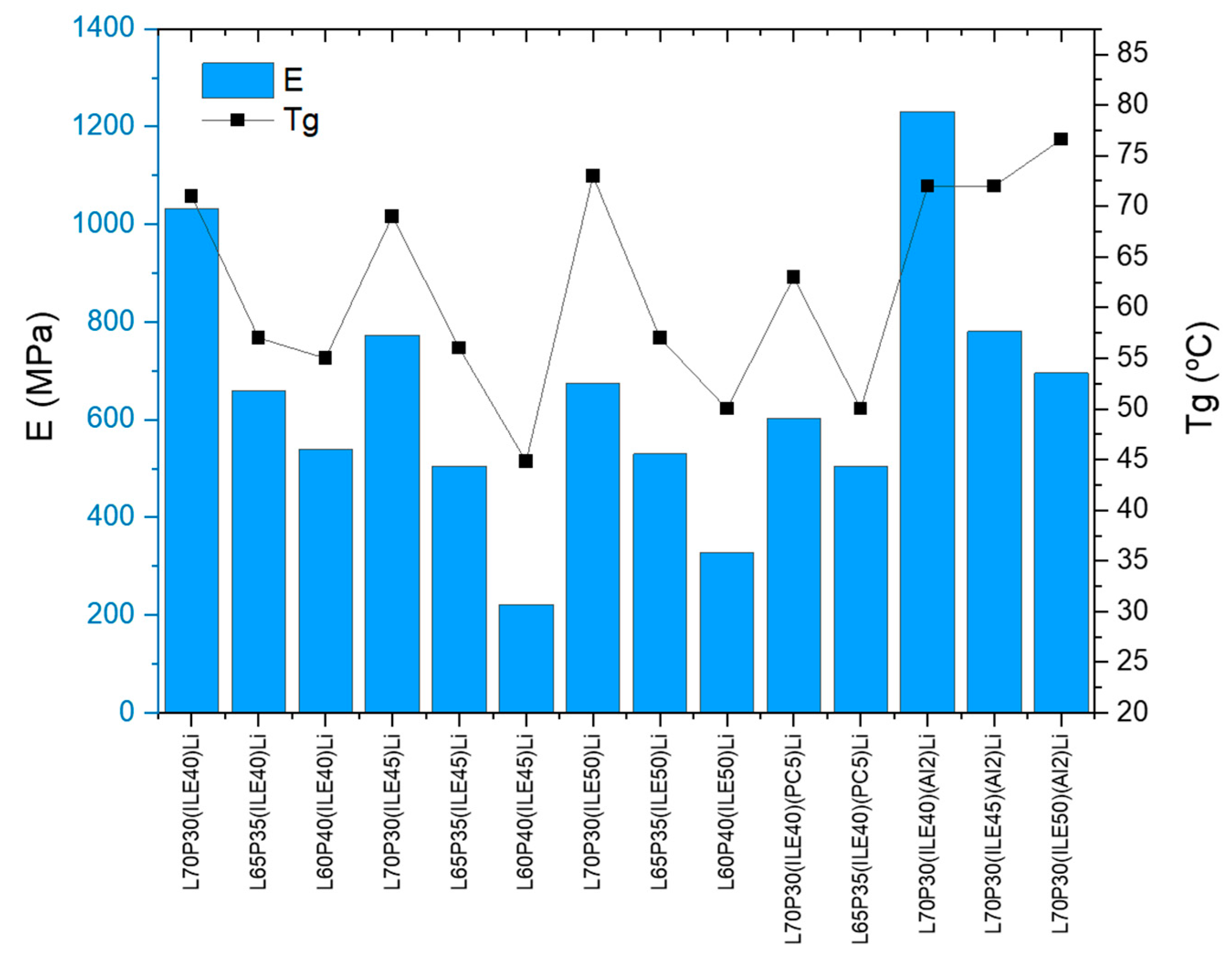
| Entry | Sample | Tg (°C) | E′ (MPa) (T = 30 °C) | E″ (MPa) (T = 30 °C) |
|---|---|---|---|---|
| 1 | L70P30(ILE40)Li | 70.7 ± 0.9 | 1032 ± 41 | 94 ± 6 |
| 2 | L65P35(ILE40)Li | 57 ± 2 | 659 ± 27 | 108 ± 8 |
| 3 | L60P40(ILE40)Li | 55 ± 2 | 539 ± 87 | 104 ± 17 |
| 4 | L70P30(ILE45)Li | 69 ± 2 | 773 ± 127 | 71 ± 2 |
| 5 | L65P35(ILE45)Li | 56 ± 3 | 506 ± 93 | 82 ± 4 |
| 6 | L60P40(ILE45)Li | 44.8 ± 0.5 | 222 ± 19 | 72 ± 3 |
| 7 | L70P30(ILE50)Li | 73 ± 1 | 675 ± 81 | 61.8 ± 0.9 |
| 8 | L65P35(ILE50)Li | 57 ± 4 | 530 ± 145 | 73 ± 14 |
| 9 | L60P40(ILE50)Li | 50 ± 2 | 328 ± 79 | 74 ± 12 |
| 10 | L70P30(ILE40)(PC5)Li | 63 ± 2 | 603 ± 122 | 76 ± 7 |
| 11 | L65P35(ILE40)(PC5)Li | 50 ± 1 | 504 ± 26 | 101 ± 5 |
| 12 | L70P30(ILE40)Li(Al2) | 72 ± 2 | 1231 ± 84 | 112 ± 5 |
| 13 | L70P30(ILE45)Li(Al2) | 72 ± 2 | 781 ± 77 | 74 ± 3 |
| 14 | L70P30(ILE50)Li(Al2) | 76.6 ± 0.8 | 696 ± 18 | 69 ± 1 |
| Entry | Sample | σ0 (S·cm−1) | σ1 (S·cm−1) | Csp (μF/cm2) | Stability Range (V) |
|---|---|---|---|---|---|
| 1 | L70P30(ILE40)Li | 0.30 | 0.3 | ||
| 2 | L65P35(ILE40)Li | 1.74 | 0.3 | ||
| 3 | L60P40(ILE40)Li | 3.76 | 0.8 | ||
| 4 | L70P30(ILE45)Li | 21.22 | 1.2 | ||
| 5 | L65P35(ILE45)Li | 44.03 | 1.0 | ||
| 6 | L60P40(ILE45)Li | 109.39 | 1.7 | ||
| 7 | L70P30(ILE50)Li | 29.64 | 2.2 | ||
| 8 | L65P35(ILE50)Li | 18.44 | 1.1 | ||
| 9 | L60P40(ILE50)Li | 67.57 | 1.8 | ||
| 10 | L70P30(ILE40)(PC5)Li | 7.50 | 1.4 | ||
| 11 | L65P35(ILE40)(PC5)Li | 30.44 | 1.2 | ||
| 12 | L70P30(ILE40)Li(Al2) | 4.61 | 2.4 | ||
| 13 | L70P30(ILE45)Li(Al2) | 9.11 | 2.6 | ||
| 14 | L70P30(ILE50)Li(Al2) | 2.95 | 2.3 |
| Entry | Sample | Tg (°C) | E′ (MPa) (T = 30 °C) | σ0 (S·cm−1) | σ1 (S·cm−1) |
|---|---|---|---|---|---|
| 1 1,2 | L65P35(ILE30) | 65 ± 2 | 1202 ± 10 | - | |
| 2 1 | L65P35(ILE40) | 68 ± 2 | 495 ± 60 | - | |
| 3 1 | L65P35(ILE45) | 63 ± 3 | 401 ± 80 | - | |
| 4 1,2 | L65P35(ILE30)Al2 | 83 ± 1 | 1213 ± 164 | ||
| 5 1 | L65P35(ILE40)Al2 | 70 ± 2 | 461 ± 62 | ||
| 6 1 | L65P35(ILE45)Al2 | 65 ± 3 | 469 ± 89 | ||
| 7 | L65P35(ILE30)Li | 68 ± 1 | 1235 ± 20 | - | |
| 8 | L65P35(ILE30)Li(Al2) | 85 ± 1 | 1224 ± 103 |
Disclaimer/Publisher’s Note: The statements, opinions and data contained in all publications are solely those of the individual author(s) and contributor(s) and not of MDPI and/or the editor(s). MDPI and/or the editor(s) disclaim responsibility for any injury to people or property resulting from any ideas, methods, instructions or products referred to in the content. |
© 2024 by the authors. Licensee MDPI, Basel, Switzerland. This article is an open access article distributed under the terms and conditions of the Creative Commons Attribution (CC BY) license (https://creativecommons.org/licenses/by/4.0/).
Share and Cite
Muñoz, B.K.; Lozano, J.; Sánchez, M.; Ureña, A. Hybrid Solid Polymer Electrolytes Based on Epoxy Resins, Ionic Liquid, and Ceramic Nanoparticles for Structural Applications. Polymers 2024, 16, 2048. https://doi.org/10.3390/polym16142048
Muñoz BK, Lozano J, Sánchez M, Ureña A. Hybrid Solid Polymer Electrolytes Based on Epoxy Resins, Ionic Liquid, and Ceramic Nanoparticles for Structural Applications. Polymers. 2024; 16(14):2048. https://doi.org/10.3390/polym16142048
Chicago/Turabian StyleMuñoz, Bianca K., Jorge Lozano, María Sánchez, and Alejandro Ureña. 2024. "Hybrid Solid Polymer Electrolytes Based on Epoxy Resins, Ionic Liquid, and Ceramic Nanoparticles for Structural Applications" Polymers 16, no. 14: 2048. https://doi.org/10.3390/polym16142048